EP1367316A2 - Intra-cylinder tubular pressure regulator - Google Patents
Intra-cylinder tubular pressure regulator Download PDFInfo
- Publication number
- EP1367316A2 EP1367316A2 EP03252905A EP03252905A EP1367316A2 EP 1367316 A2 EP1367316 A2 EP 1367316A2 EP 03252905 A EP03252905 A EP 03252905A EP 03252905 A EP03252905 A EP 03252905A EP 1367316 A2 EP1367316 A2 EP 1367316A2
- Authority
- EP
- European Patent Office
- Prior art keywords
- fluid
- pressure
- control system
- valve
- cavity
- Prior art date
- Legal status (The legal status is an assumption and is not a legal conclusion. Google has not performed a legal analysis and makes no representation as to the accuracy of the status listed.)
- Withdrawn
Links
Images


Classifications
-
- F—MECHANICAL ENGINEERING; LIGHTING; HEATING; WEAPONS; BLASTING
- F17—STORING OR DISTRIBUTING GASES OR LIQUIDS
- F17C—VESSELS FOR CONTAINING OR STORING COMPRESSED, LIQUEFIED OR SOLIDIFIED GASES; FIXED-CAPACITY GAS-HOLDERS; FILLING VESSELS WITH, OR DISCHARGING FROM VESSELS, COMPRESSED, LIQUEFIED, OR SOLIDIFIED GASES
- F17C13/00—Details of vessels or of the filling or discharging of vessels
- F17C13/04—Arrangement or mounting of valves
-
- F—MECHANICAL ENGINEERING; LIGHTING; HEATING; WEAPONS; BLASTING
- F17—STORING OR DISTRIBUTING GASES OR LIQUIDS
- F17C—VESSELS FOR CONTAINING OR STORING COMPRESSED, LIQUEFIED OR SOLIDIFIED GASES; FIXED-CAPACITY GAS-HOLDERS; FILLING VESSELS WITH, OR DISCHARGING FROM VESSELS, COMPRESSED, LIQUEFIED, OR SOLIDIFIED GASES
- F17C13/00—Details of vessels or of the filling or discharging of vessels
- F17C13/12—Arrangements or mounting of devices for preventing or minimising the effect of explosion ; Other safety measures
- F17C13/123—Arrangements or mounting of devices for preventing or minimising the effect of explosion ; Other safety measures for gas bottles, cylinders or reservoirs for tank vehicles or for railway tank wagons
-
- G—PHYSICS
- G05—CONTROLLING; REGULATING
- G05D—SYSTEMS FOR CONTROLLING OR REGULATING NON-ELECTRIC VARIABLES
- G05D16/00—Control of fluid pressure
- G05D16/04—Control of fluid pressure without auxiliary power
- G05D16/06—Control of fluid pressure without auxiliary power the sensing element being a flexible membrane, yielding to pressure, e.g. diaphragm, bellows, capsule
- G05D16/063—Control of fluid pressure without auxiliary power the sensing element being a flexible membrane, yielding to pressure, e.g. diaphragm, bellows, capsule the sensing element being a membrane
- G05D16/0644—Control of fluid pressure without auxiliary power the sensing element being a flexible membrane, yielding to pressure, e.g. diaphragm, bellows, capsule the sensing element being a membrane the membrane acting directly on the obturator
- G05D16/0647—Control of fluid pressure without auxiliary power the sensing element being a flexible membrane, yielding to pressure, e.g. diaphragm, bellows, capsule the sensing element being a membrane the membrane acting directly on the obturator using one membrane without spring
-
- F—MECHANICAL ENGINEERING; LIGHTING; HEATING; WEAPONS; BLASTING
- F17—STORING OR DISTRIBUTING GASES OR LIQUIDS
- F17C—VESSELS FOR CONTAINING OR STORING COMPRESSED, LIQUEFIED OR SOLIDIFIED GASES; FIXED-CAPACITY GAS-HOLDERS; FILLING VESSELS WITH, OR DISCHARGING FROM VESSELS, COMPRESSED, LIQUEFIED, OR SOLIDIFIED GASES
- F17C2201/00—Vessel construction, in particular geometry, arrangement or size
- F17C2201/01—Shape
- F17C2201/0104—Shape cylindrical
-
- F—MECHANICAL ENGINEERING; LIGHTING; HEATING; WEAPONS; BLASTING
- F17—STORING OR DISTRIBUTING GASES OR LIQUIDS
- F17C—VESSELS FOR CONTAINING OR STORING COMPRESSED, LIQUEFIED OR SOLIDIFIED GASES; FIXED-CAPACITY GAS-HOLDERS; FILLING VESSELS WITH, OR DISCHARGING FROM VESSELS, COMPRESSED, LIQUEFIED, OR SOLIDIFIED GASES
- F17C2201/00—Vessel construction, in particular geometry, arrangement or size
- F17C2201/03—Orientation
- F17C2201/032—Orientation with substantially vertical main axis
-
- F—MECHANICAL ENGINEERING; LIGHTING; HEATING; WEAPONS; BLASTING
- F17—STORING OR DISTRIBUTING GASES OR LIQUIDS
- F17C—VESSELS FOR CONTAINING OR STORING COMPRESSED, LIQUEFIED OR SOLIDIFIED GASES; FIXED-CAPACITY GAS-HOLDERS; FILLING VESSELS WITH, OR DISCHARGING FROM VESSELS, COMPRESSED, LIQUEFIED, OR SOLIDIFIED GASES
- F17C2201/00—Vessel construction, in particular geometry, arrangement or size
- F17C2201/05—Size
- F17C2201/054—Size medium (>1 m3)
-
- F—MECHANICAL ENGINEERING; LIGHTING; HEATING; WEAPONS; BLASTING
- F17—STORING OR DISTRIBUTING GASES OR LIQUIDS
- F17C—VESSELS FOR CONTAINING OR STORING COMPRESSED, LIQUEFIED OR SOLIDIFIED GASES; FIXED-CAPACITY GAS-HOLDERS; FILLING VESSELS WITH, OR DISCHARGING FROM VESSELS, COMPRESSED, LIQUEFIED, OR SOLIDIFIED GASES
- F17C2201/00—Vessel construction, in particular geometry, arrangement or size
- F17C2201/05—Size
- F17C2201/056—Small (<1 m3)
-
- F—MECHANICAL ENGINEERING; LIGHTING; HEATING; WEAPONS; BLASTING
- F17—STORING OR DISTRIBUTING GASES OR LIQUIDS
- F17C—VESSELS FOR CONTAINING OR STORING COMPRESSED, LIQUEFIED OR SOLIDIFIED GASES; FIXED-CAPACITY GAS-HOLDERS; FILLING VESSELS WITH, OR DISCHARGING FROM VESSELS, COMPRESSED, LIQUEFIED, OR SOLIDIFIED GASES
- F17C2205/00—Vessel construction, in particular mounting arrangements, attachments or identifications means
- F17C2205/03—Fluid connections, filters, valves, closure means or other attachments
- F17C2205/0302—Fittings, valves, filters, or components in connection with the gas storage device
- F17C2205/0338—Pressure regulators
-
- F—MECHANICAL ENGINEERING; LIGHTING; HEATING; WEAPONS; BLASTING
- F17—STORING OR DISTRIBUTING GASES OR LIQUIDS
- F17C—VESSELS FOR CONTAINING OR STORING COMPRESSED, LIQUEFIED OR SOLIDIFIED GASES; FIXED-CAPACITY GAS-HOLDERS; FILLING VESSELS WITH, OR DISCHARGING FROM VESSELS, COMPRESSED, LIQUEFIED, OR SOLIDIFIED GASES
- F17C2205/00—Vessel construction, in particular mounting arrangements, attachments or identifications means
- F17C2205/03—Fluid connections, filters, valves, closure means or other attachments
- F17C2205/0388—Arrangement of valves, regulators, filters
- F17C2205/0391—Arrangement of valves, regulators, filters inside the pressure vessel
-
- F—MECHANICAL ENGINEERING; LIGHTING; HEATING; WEAPONS; BLASTING
- F17—STORING OR DISTRIBUTING GASES OR LIQUIDS
- F17C—VESSELS FOR CONTAINING OR STORING COMPRESSED, LIQUEFIED OR SOLIDIFIED GASES; FIXED-CAPACITY GAS-HOLDERS; FILLING VESSELS WITH, OR DISCHARGING FROM VESSELS, COMPRESSED, LIQUEFIED, OR SOLIDIFIED GASES
- F17C2223/00—Handled fluid before transfer, i.e. state of fluid when stored in the vessel or before transfer from the vessel
- F17C2223/01—Handled fluid before transfer, i.e. state of fluid when stored in the vessel or before transfer from the vessel characterised by the phase
- F17C2223/0107—Single phase
- F17C2223/0123—Single phase gaseous, e.g. CNG, GNC
-
- F—MECHANICAL ENGINEERING; LIGHTING; HEATING; WEAPONS; BLASTING
- F17—STORING OR DISTRIBUTING GASES OR LIQUIDS
- F17C—VESSELS FOR CONTAINING OR STORING COMPRESSED, LIQUEFIED OR SOLIDIFIED GASES; FIXED-CAPACITY GAS-HOLDERS; FILLING VESSELS WITH, OR DISCHARGING FROM VESSELS, COMPRESSED, LIQUEFIED, OR SOLIDIFIED GASES
- F17C2223/00—Handled fluid before transfer, i.e. state of fluid when stored in the vessel or before transfer from the vessel
- F17C2223/03—Handled fluid before transfer, i.e. state of fluid when stored in the vessel or before transfer from the vessel characterised by the pressure level
- F17C2223/035—High pressure (>10 bar)
-
- F—MECHANICAL ENGINEERING; LIGHTING; HEATING; WEAPONS; BLASTING
- F17—STORING OR DISTRIBUTING GASES OR LIQUIDS
- F17C—VESSELS FOR CONTAINING OR STORING COMPRESSED, LIQUEFIED OR SOLIDIFIED GASES; FIXED-CAPACITY GAS-HOLDERS; FILLING VESSELS WITH, OR DISCHARGING FROM VESSELS, COMPRESSED, LIQUEFIED, OR SOLIDIFIED GASES
- F17C2225/00—Handled fluid after transfer, i.e. state of fluid after transfer from the vessel
- F17C2225/01—Handled fluid after transfer, i.e. state of fluid after transfer from the vessel characterised by the phase
- F17C2225/0107—Single phase
- F17C2225/0123—Single phase gaseous, e.g. CNG, GNC
-
- F—MECHANICAL ENGINEERING; LIGHTING; HEATING; WEAPONS; BLASTING
- F17—STORING OR DISTRIBUTING GASES OR LIQUIDS
- F17C—VESSELS FOR CONTAINING OR STORING COMPRESSED, LIQUEFIED OR SOLIDIFIED GASES; FIXED-CAPACITY GAS-HOLDERS; FILLING VESSELS WITH, OR DISCHARGING FROM VESSELS, COMPRESSED, LIQUEFIED, OR SOLIDIFIED GASES
- F17C2225/00—Handled fluid after transfer, i.e. state of fluid after transfer from the vessel
- F17C2225/03—Handled fluid after transfer, i.e. state of fluid after transfer from the vessel characterised by the pressure level
- F17C2225/033—Small pressure, e.g. for liquefied gas
-
- F—MECHANICAL ENGINEERING; LIGHTING; HEATING; WEAPONS; BLASTING
- F17—STORING OR DISTRIBUTING GASES OR LIQUIDS
- F17C—VESSELS FOR CONTAINING OR STORING COMPRESSED, LIQUEFIED OR SOLIDIFIED GASES; FIXED-CAPACITY GAS-HOLDERS; FILLING VESSELS WITH, OR DISCHARGING FROM VESSELS, COMPRESSED, LIQUEFIED, OR SOLIDIFIED GASES
- F17C2225/00—Handled fluid after transfer, i.e. state of fluid after transfer from the vessel
- F17C2225/03—Handled fluid after transfer, i.e. state of fluid after transfer from the vessel characterised by the pressure level
- F17C2225/038—Subatmospheric pressure
-
- F—MECHANICAL ENGINEERING; LIGHTING; HEATING; WEAPONS; BLASTING
- F17—STORING OR DISTRIBUTING GASES OR LIQUIDS
- F17C—VESSELS FOR CONTAINING OR STORING COMPRESSED, LIQUEFIED OR SOLIDIFIED GASES; FIXED-CAPACITY GAS-HOLDERS; FILLING VESSELS WITH, OR DISCHARGING FROM VESSELS, COMPRESSED, LIQUEFIED, OR SOLIDIFIED GASES
- F17C2227/00—Transfer of fluids, i.e. method or means for transferring the fluid; Heat exchange with the fluid
- F17C2227/04—Methods for emptying or filling
- F17C2227/048—Methods for emptying or filling by maintaining residual pressure
-
- F—MECHANICAL ENGINEERING; LIGHTING; HEATING; WEAPONS; BLASTING
- F17—STORING OR DISTRIBUTING GASES OR LIQUIDS
- F17C—VESSELS FOR CONTAINING OR STORING COMPRESSED, LIQUEFIED OR SOLIDIFIED GASES; FIXED-CAPACITY GAS-HOLDERS; FILLING VESSELS WITH, OR DISCHARGING FROM VESSELS, COMPRESSED, LIQUEFIED, OR SOLIDIFIED GASES
- F17C2260/00—Purposes of gas storage and gas handling
- F17C2260/03—Dealing with losses
- F17C2260/035—Dealing with losses of fluid
- F17C2260/036—Avoiding leaks
-
- Y—GENERAL TAGGING OF NEW TECHNOLOGICAL DEVELOPMENTS; GENERAL TAGGING OF CROSS-SECTIONAL TECHNOLOGIES SPANNING OVER SEVERAL SECTIONS OF THE IPC; TECHNICAL SUBJECTS COVERED BY FORMER USPC CROSS-REFERENCE ART COLLECTIONS [XRACs] AND DIGESTS
- Y10—TECHNICAL SUBJECTS COVERED BY FORMER USPC
- Y10T—TECHNICAL SUBJECTS COVERED BY FORMER US CLASSIFICATION
- Y10T137/00—Fluid handling
- Y10T137/7722—Line condition change responsive valves
- Y10T137/7781—With separate connected fluid reactor surface
- Y10T137/7793—With opening bias [e.g., pressure regulator]
- Y10T137/7809—Reactor surface separated by apertured partition
- Y10T137/7812—Valve stem passes through the aperture
- Y10T137/7814—Reactor is an inverted cup having liquid seal
- Y10T137/7816—Valve head in inlet chamber
-
- Y—GENERAL TAGGING OF NEW TECHNOLOGICAL DEVELOPMENTS; GENERAL TAGGING OF CROSS-SECTIONAL TECHNOLOGIES SPANNING OVER SEVERAL SECTIONS OF THE IPC; TECHNICAL SUBJECTS COVERED BY FORMER USPC CROSS-REFERENCE ART COLLECTIONS [XRACs] AND DIGESTS
- Y10—TECHNICAL SUBJECTS COVERED BY FORMER USPC
- Y10T—TECHNICAL SUBJECTS COVERED BY FORMER US CLASSIFICATION
- Y10T137/00—Fluid handling
- Y10T137/7722—Line condition change responsive valves
- Y10T137/7781—With separate connected fluid reactor surface
- Y10T137/7793—With opening bias [e.g., pressure regulator]
- Y10T137/7809—Reactor surface separated by apertured partition
- Y10T137/7812—Valve stem passes through the aperture
- Y10T137/7818—Valve head in inlet chamber
- Y10T137/7819—Rectilinear valve stem rigid with reactor surface
-
- Y—GENERAL TAGGING OF NEW TECHNOLOGICAL DEVELOPMENTS; GENERAL TAGGING OF CROSS-SECTIONAL TECHNOLOGIES SPANNING OVER SEVERAL SECTIONS OF THE IPC; TECHNICAL SUBJECTS COVERED BY FORMER USPC CROSS-REFERENCE ART COLLECTIONS [XRACs] AND DIGESTS
- Y10—TECHNICAL SUBJECTS COVERED BY FORMER USPC
- Y10T—TECHNICAL SUBJECTS COVERED BY FORMER US CLASSIFICATION
- Y10T137/00—Fluid handling
- Y10T137/8593—Systems
- Y10T137/87917—Flow path with serial valves and/or closures
-
- Y—GENERAL TAGGING OF NEW TECHNOLOGICAL DEVELOPMENTS; GENERAL TAGGING OF CROSS-SECTIONAL TECHNOLOGIES SPANNING OVER SEVERAL SECTIONS OF THE IPC; TECHNICAL SUBJECTS COVERED BY FORMER USPC CROSS-REFERENCE ART COLLECTIONS [XRACs] AND DIGESTS
- Y10—TECHNICAL SUBJECTS COVERED BY FORMER USPC
- Y10T—TECHNICAL SUBJECTS COVERED BY FORMER US CLASSIFICATION
- Y10T137/00—Fluid handling
- Y10T137/8593—Systems
- Y10T137/87917—Flow path with serial valves and/or closures
- Y10T137/87925—Separable flow path section, valve or closure in each
Definitions
- the present invention generally relates to improvements in a fluid pressure regulator, and more particularly relates to an improved fluid pressure regulator used within a fluid control system.
- Pressurized fluid containers such as gas containers or cylinders
- cylinders storing high-pressure hydrides have been used in semiconductor manufacturing processes.
- the high-pressure fluid such as a gas
- the high-pressure fluid stored in fluid cylinders is not dispensed at high pressure.
- a pressure regulator or other flow restriction device used in conjunction with a cylinder typically delivers, or dispenses, the fluid from the cylinder at a pressure substantially lower than that inside the cylinder.
- a self-regulating mechanical device, or pressure regulator is used to reduce the pressure of a dispensed gas.
- pressure regulators incorporate a diaphragm or a piston connected to a valve as a way of reducing the pressure of the dispensed gas.
- a pressure regulator is discrete from the fluid cylinder and from the valve that selectively controls the dispensing of the gas from the cylinder. Gas under high pressure, however, may escape at a dangerously high rate from a fluid cylinder if the cylinder valve is inadvertently opened.
- pressure reduction devices such as a restrictive flow orifice or an integrated valve, as part of the cylinder assembly.
- An integrated valve typically includes a low-pressure shut-off valve and a pressure regulator within the same fluid dispensing assembly.
- a pressure regulator may be set to reduce the pressure of a gas to subatmospheric pressure, i.e., less than 1 bar absolute pressure.
- a fluid dispensing, or fluid control, system utilizing a subatmospheric pressure regulator offers a safety advantage. That is, gas is not dispensed from the system, even if the cylinder valve is opened, unless the pressure on the downstream side of the pressure regulator is lower than atmospheric pressure. In other words, gas is dispensed from the system only when a downstream device or condition draws the gas from a fluid outlet of the dispensing assembly, i.e., by drawing a vacuum.
- the method of actively extracting gas from a dispensing assembly of a gas dispensing system is used in, for example, self-contained underwater breathing apparatus ("SCUBA”) and in systems designed to supply hazardous toxic gases to semiconductor manufacturing systems.
- SCUBA self-contained underwater breathing apparatus
- Positioning an integrated valve substantially or entirely within a fluid cylinder protects the pressure regulator of the integrated valve from external forces and damage associated with moving the cylinder. Further, installing an integrated valve within a fluid cylinder makes the gas dispensing system more compact and easier to handle.
- fluid cylinders having an opening greater than the standard 3 ⁇ 4 inch (1.9 cm) NGT are more prone to leaks, are heavier, and are more expensive to manufacture.
- the cylinder openings of standard fluid cylinders are, for reasons of weight, containment integrity and manufacturing cost, made as small as possible. Further, a large number of standard fluid cylinders already exist. The regulators described in Wang I and Wang II, however, cannot be used with these standard cylinders.
- European Patent Application 0 512 553 A1 (“MEVA application”), published November 11, 1992, is directed to a superatmospheric pressure controlled reducing valve designed for use in respirators and adapted to operate exclusively in the superatmospheric pressure breathing regime.
- the valve is controlled by one or more straight stay or stays immediately confining cavity having an inlet.
- the stays In an inoperative state, where the cavity inlet is not exposed to any breathing medium pressure, the stays are tight and hold a valve member in an open position open until pressurized breathing medium passes through the inlet.
- the stays bend, get shorter and move the valve member to a closed position cutting off the breathing medium flow.
- the superatmospheric pressure in the cavity drops whereby the stays begin to straighten to reassume their original shape and move the valve member from it closed position to restore the flow of breathing medium.
- the MEVA application does not teach or suggest the use of the superatmospheric pressure controlled reducing valve with a semiconductor manufacturing system, or with toxic gases and does not teach or suggest positioning, or interiorly disposing, the superatmospheric pressure controlled reducing valve within a fluid cylinder.
- the overpressure inflates the diagram from its untensioned state causing the stays to bend outwardly and move the closed moveable end towards the fixed end and thereby move the head of the valve stem towards, and eventually to close, the valve seat.
- the resultant reduction of pressure within the diaphragm allows it to return by its resilient flexibility towards its untensioned state thereby relaxing the stays and moving the valve stem away from the valve seat.
- United States Patent No 6,257,000 issued to Wang (“Wang III”) and granted July 10, 2001 discloses a fluid storage and dispensing system having a fluid dispensing assembly coupled in fluid flow with an opening in a vessel; an adjustable set point pressure regulator in the interior of the vessel to provide fluid to the dispensing assembly at a set point-determined pressure, and set point adjusting means external to the vessel to selectively vary the set point of said pressure regulator.
- the adjusting means can be a pneumatic controller for the pressure regulator and the latter may be of the type having a diaphragm coupled with a poppet retaining wafer connected to the stem of a poppet element.
- a fluid pressure regulator has been developed that includes a fluid inlet, a fluid outlet, a first fluid flow path between the fluid inlet and the fluid outlet, a valve seat positioned in the first fluid flow path and dividing the fluid inlet and the fluid outlet, a valve element regulating flow through the valve seat, and a generally cylindrical membrane defining an inflatable fluid cavity that includes a wall portion that moves responsive to inflation and deflation of the cavity, a second fluid flow path communicating between the cavity and a source of pressure outside the cavity, and a link transmitting the movement of the wall portion to the valve element, thereby moving the valve element with respect to the valve seat responsive to inflation and deflation of the cavity.
- the valve element regulating flow between the fluid inlet and the fluid outlet may be a poppet comprising a valve disk and a valve stem, in which case, the valve stem can define the link.
- the fluid pressure regulator further comprises at least one radially flexible stiffening member extending generally axially along the membrane and having a first portion, a second portion spaced axially from the first portion, and a third portion between the first and second portions.
- the third portion is positioned to contact and be flexed by the membrane when the membrane moves radially.
- the first portion of the stiffening member is secured with respect to a first end cap and the second portion of the stiffening member is secured with respect to a second end cap.
- Certain embodiments of the present invention utilize the fluid pressure regulator within a fluid control system for dispensing high-pressure fluid at reduced pressure.
- the fluid control system comprises a container for storage and dispensing of a fluid and a fluid flow control device connected to the outlet of the container.
- the fluid flow control device comprises at least a first fluid flow path having a main fluid inlet in fluid communication with the container and a main fluid outlet, and a high-pressure shut-off valve in the first fluid flow path to selectively open or close the fluid flow path.
- the fluid pressure regulator is positioned in the first fluid flow path for providing fluid at the main fluid outlet at a selected pressure.
- the fluid pressure regulator is downstream of the high-pressure shut-off valve and located inside the container.
- FIG. 1 shows a fluid control system 10 according to an embodiment of the present invention.
- the system 10 includes a pressurized fluid container or cylinder 12 having an outlet port 14 and a fluid flow control device, such as an integrated valve assembly 16.
- the integrated valve assembly 16 includes a main body 18, a main fluid inlet 20, a high-pressure shut-off valve 22, a pressure regulator 24, a low-pressure shut-off valve 26, a main fluid outlet 28, a bursting disc safety member 30 and a vent 32.
- a fluid flow path 34 progresses from the main fluid inlet 20 to the high-pressure shut-off valve 22, then from the valve 22 to the pressure regulator 24.
- the fluid flow path 34 continues from the pressure regulator 24 to the low-pressure shut-off valve 26 and through the main fluid outlet 28.
- the high-pressure shut-off valve 22 regulates flow of the fluid in the fluid flow path 34 between the inlet 20 and the regulator 24.
- the pressure regulator 24 regulates flow of the fluid in the fluid flow path 34 between the high-pressure shut-off valve 22 and the low-pressure shut-off valve 26.
- the low-pressure shut-off valve 26 in turn, regulates flow and delivers the fluid at a predetermined pressure through the fluid flow path 34 between the regulator 24 and the main fluid outlet 28.
- the integrated valve assembly 16 is affixed to the outlet port 14 of the cylinder 12 in a conventional manner, such as by providing mating threads on the exterior of the integrated valve assembly 16 and on the interior of the outlet port 14. Alternatively, the integrated valve assembly 16 may be welded into the outlet port 14.
- fluid flows from the interior of the cylinder 12 and enters the fluid flow path 34 through the main fluid inlet 20.
- the fluid then travels from the main fluid inlet 20 through the fluid flow path 34 to the high-pressure shut-off valve 22.
- the fluid After flowing through the high-pressure shut-off valve 22 (when the high-pressure shut-off valve 22 is opened), the fluid travels along the fluid flow path 34 to the pressure regulator 24.
- the fluid then travels through the pressure regulator 24.
- the fluid After passing through the pressure regulator 24, the fluid travels along the fluid flow path 34 and encounters the low-pressure shut-off valve 26.
- the low-pressure shut-off valve 26 When the low-pressure shut-off valve 26 is opened, the fluid then passes from the system 10 at the main fluid outlet 28.
- the pressure regulator 24 includes a regulator inlet 44, a valve seat 46 dividing the regulator 24 into a high pressure side in the inlet 44 and a low-pressure side downstream of the valve seat 46, a poppet 48 movably positioned to seat on the valve seat 46, and a regulator outlet 50 communicating with the low-pressure side of the valve seat 46.
- the poppet 48 includes a valve stem 52 and a valve head or disk 54 located at one end of the valve stem 52, adjacent to the seat 46.
- a cylindrical expandable membrane 56 in the form of an inflatable tubular diaphragm is secured by a fixed inlet end 58 to the main body 18 of the integrated valve assembly 16, and capped at the other end by a movable plate 60.
- the cylindrical expandable membrane 56 separates an inner fluid cavity 62 from an outer fluid cavity 64.
- the membrane 56 is radially inflatable or deflatable responsive to pressure differences between the inner fluid cavity 62 and the outer fluid cavity 64. (shown inflated in Figure 3, and otherwise shown deflated).
- the inner fluid cavity 62 communicates with the low-pressure outlet 50 of the regulator 24 via a second fluid flow path 65.
- the outer fluid cavity 64 is further defined by a substantially rigid housing 66 connected to and supported by the main body 18 of the integrated valve 16.
- the housing 66 isolates the interior of the regulator 24 from the pressure inside the cylinder 12.
- the outer fluid cavity 64 is vented to the atmosphere through the vent 32 to define a reference pressure.
- the expandable membrane 56 may be fabricated from any of a variety of materials, such as elastomeric film.
- the membrane 56 is stiffened by radially flexible, axially relatively inflexible stiffening members 68 extending axially between and connected at their respective ends to the main body 18 of the integrated valve assembly 16 and the movable plate 60.
- the regulator 24 regulates pressure at its outlet 50 as follows.
- the cylindrical expandable membrane 56 moves the valve stem 48 responsive to the pressure on the low-pressure side of the valve seat 46 to maintain the low-pressure side at a desired setpoint pressure.
- Outward inflation flexes the centers of the stiffening members 68 radially outward. Bending the stiffening members 68 outward at the center draws their ends toward each other and lifts the movable plate 60. Upward motion of the plate 60 is transmitted by the valve stem 52 to the valve disk 54, which moves toward and (if the inflation pressure is at its setpoint) bears against the seat 46.
- valve disk 54 stops the flow of high-pressure fluid from the regulator inlet into the inner fluid cavity 62, responsive to elevated pressure in the low-pressure side of the regulator 24.
- the pressure at which inflation of the membrane 56 seats the valve disk 54 on the valve seat 46 is the setpoint of the regulator, and defines the highest pressure the regulator will allow at the low-pressure outlet 50.
- the setpoint may be adjustable by a set point adjusting member 67, such as a screw or other such adjustment means, which moves the valve stem 52, thereby changing the distance between the valve disk 54 and the valve seat 46.
- Such an adjustment means is preferably lockable at any desired position.
- the membrane 56 optionally is generally cylindrical, as in the illustrated embodiments, and can be elongated as necessary to increase its valve seating force, generated in response to a given pressure difference between the inner and outer cavities 62 and 64, without increasing its radial dimensions.
- the pressure regulator 24 can be slender enough to be positioned inside the cylinder 12.
- the tubular, slender shape of the pressure regulator 24 allows it to safely pass through the outlet port 14 of the cylinder 12.
- the cylinder 12 can be a standard fluid cylinder wherein the outlet port 14 is 3 ⁇ 4 inch (1.9 cm) NGT (National Gas Taper).
- NGT National Gas Taper
- the placement of the pressure regulator 24 inside the cylinder 12 protects the pressure regulator 24 from damage by external forces, stresses and strains.
- the outlet port 14 of the cylinder 12 may be any size that is suitable for passage of the pressure regulator 24 into the cylinder 12.
- the bursting disc safety member 30 is a thin, circular diaphragm made of corrosion-proof metal.
- the bursting disc safety member 30 is intended to break at a defined pressure.
- the main body 18 supports the high-pressure shut-off valve 22, the low-pressure shut-off valve 26 and the pressure regulator 24.
- the fluid flow path 34 may provide a fill path for the cylinder 12.
- liquefied gas at a low pressure which may be below the setpoint of the regulator, may be filled via fluid flow path 34.
- a separate fluid fill inlet and fluid fill path may be formed within the cylinder 12.
- a fluid fill valve may also be positioned within the fluid fill path.
- the pressure regulator 24, the high-pressure shut-off valve 22 and the low-pressure shut-off valve 26 may be discrete devices not included in a common integrated valve assembly 16.
- the system 10 does not require the bursting disc safety member 30.
- the system 10 does not necessarily require the stiffening members 68.
- the system 10 does not require the rigid housing 66.
- the present invention can include an expandable membrane 56 that can expand without a rigid housing 66 limiting the degree of expansion.
- the stiffening members 68 may be flexible metal or plastic strips or plates. Alternatively, the stiffening members 68 may comprise a diaphragm that is stiffer than the expandable membrane 56, and which encompasses the more expandable membrane 56. The stiffening members 68 and the expandable membrane 56, both of which are connected to the movable plate 60, pull the movable plate 60 toward the main body 18 as the stiffening members 68 bow out and the membrane 56 inflates.
- FIG 4 shows an absolute pressure regulator 70 according to another embodiment of the present invention.
- the absolute pressure regulator 70 includes an expandable membrane that is an expandable longitudinally corrugated tube 72 formed of metal (although other material can instead be used).
- the absolute pressure regulator 70 of this embodiment utilizes the corrugated tube 72 to perform a similar function.
- One end of the corrugated tube 72 is connected to the main body 18, while another end of the corrugated tube 72 is connected to the movable plate 60.
- the corrugated tube 72 expands radially and contracts axially when fluid exerts pressure on the interior walls of the corrugated tube 72, and contracts radially and expands axially when fluid exerts a greater pressure on the exterior of the corrugated tube 72 as compared to the pressure within the corrugated tube 72.
- the axial expansion of the corrugated tube 72 causes the poppet 48 to contact the valve seat 46 in a similar fashion as the expandable membrane 56 and the stiffening members 68 (as shown in Figure 1-3) act to cause the poppet 48 to contact the valve seat 46.
- the contraction of the corrugated tube 72 causes the poppet 48 to recede from the valve seat 46.
- the pressure regulator 70 is an absolute pressure regulator, no vent to atmosphere is used. Instead, a getter 74 is used to maintain a vacuum condition within the outer cavity 64 by removing traces of gas within the outer cavity 64.
- the getter 74 is a reactive substance, such as zirconium or calcium, which is incorporated into the absolute pressure regulator 70 to absorb residual gases and moisture.
- a sealed off vacuum space, such as the interior of the absolute pressure regulator 70, may have a small amount of getter 74 to maintain a low-pressure within that space. Without the getter 74, the interior of the absolute pressure regulator 70 would increase in pressure as absorbed moisture and other gases are released from the interior walls of the absolute pressure regulator 70.
- FIG. 7 is a schematic representation of a fluid control system 78 according to an embodiment of the present invention.
- the fluid control system 78 includes a fluid cylinder 12 having an outlet port 14 and a tubular pressure regulator 24 positioned inside the cylinder 12.
- the pressure regulator 24 includes a poppet 48.
- the system 78 also includes a residual pressure valve 80, a fluid flow path 34, a high-pressure relief valve 82, a high-pressure shut off valve 22, a filter 84, a low-pressure shut-off valve 26, a low-pressure relief valve 86 and a fluid outlet 28.
- the system 78 also includes a vent 32. If, however, the pressure regulator 24 is an absolute pressure regulator, the vent 32 is not included within the system 78. Additionally, this embodiment includes a fluid fill path 88, a fluid fill port 90 and fluid fill valve 92.
- the valve body 18 plugs the outlet port 14 of the cylinder 12.
- fluid is supplied to the cylinder 12 through the fluid fill path 88. That is, an external fluid supply is connected to the fluid fill port 90, so fluid passes from the supply into the fluid fill path 88.
- the fluid fill valve 92 selectively opens and closes the fluid fill path 88.
- Fluid to be dispensed from the cylinder 12 enters the residual pressure valve 80 and passes to the high-pressure shut-off valve 22 via the fluid flow path 34.
- the high-pressure shut-off valve 22 When the high-pressure shut-off valve 22 is open, fluid then travels downstream from the high-pressure shut-off valve 22 through the filter 84 and to the poppet 48 of the pressure regulator 24.
- the pressure of the fluid passing through the poppet 48 is reduced by operation of the pressure regulator 24, as described with respect to Figure 1. Most of the fluid passed by the poppet 48 passes through the fluid flow path 34 to the low-pressure shut-off valve 26.
- the low-pressure shut-off valve 26 is opened, the fluid is dispensed through the fluid outlet 28.
- the tubular pressure regulator 24 may be set to deliver fluid at a subatmospheric, atmospheric, or superatmospheric pressure, depending on the set point of the pressure regulator 24. If the pressure regulator 24 is set to deliver fluid at subatmospheric pressure, the ambient pressure of the atmosphere ensures that fluid does not pass through the fluid outlet 28 when the outlet is not connected to an external device. That is, the pressure of the atmosphere may exert enough pressure on the fluid to keep it within the system 78.
- inflation pressure could be communicated between the outlet 50 and the outer fluid cavity 64, and the inner fluid cavity 62 could be vented to the atmosphere. This would reverse the action of the poppet 48 responsive to pressure changes.
- the orientation of the valve disk 54 and seat 46 could also be reversed so the disk 54 would seat by moving downward on the seat 46.
- the stiffening members 56 could be normally bowed inward, so inflation of the inner fluid cavity 62 straightens the stiffening members 56 and moves the end plate 60 axially downward.
- This modification would again reverse the influence of pressure changes on the poppet 48.
- Either of the two compensating changes described in the previous example could be employed as well, so the valve disk 54 would still close on the seat 46 responsive to pressure in the regulator outlet 50 reaching the setpoint pressure.
- movement of the side walls of the cylindrical expandable membrane 56 could be directly transmitted to the poppet 48 by a mechanical linkage within the inner fluid cavity 62.
- a mechanical linkage would be a parallelogram linkage having one pair of opposed pivots pulled apart by inflation of the cylindrical expandable membrane 56, thus pushing together the remaining two, axially spaced pivots of the parallelogram.
- One of the two axially spaced pivots could be linked to the poppet 48 and the other of the two axially spaced pivots could be free floating, or linked to the movable plate 60, or linked to the fixed inlet end 58.
- the floating pivot and the two adjacent links could be omitted, leaving a pair of links that function as described above in this paragraph.
- the poppet 48 By selecting one or the other of the axially spaced links to connect to the poppet 48, the poppet 48 would either be raised or lowered by inflation of the inner fluid cavity 62.
- a compound lever linkage could also be employed to provide a mechanical advantage.
- Still another example of a contemplated modification would be to fix the movable plate 60 relative to the housing 66, fix the poppet 48 relative to the inlet end 58, and mount the inlet end 58 to be axially movable.
- One of the previously described expedients such as reversing the valve and valve seat, or arranging the mechanism so inflation would straighten the stiffening members 56 instead of bending them, could again be used to complete the modification.
- pressure gauges may be added within the system.
- An active high pressure gauge which may communicate directly with the cylinder, may be used within the system.
- a passive high pressure gauge which may communicate with the fluid flow path 34 between the high pressure shut-off valve 22 and the regulator 24, may also be used.
- a low pressure gauge may be included within the fluid flow path 34, downstream of the regulator 24.
- the gauges may be mechanical display gauges, such as Bourdon tube gauges, or may be electronic gauges, which provide an electrical output.
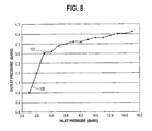
- Figure 8 is a graph showing the relationship between inlet pressure and outlet pressure of the pressure regulator.
- the flow rate is approximately 20 liters per minute.
- the plot 100 shows the relationship between inlet pressure (measured in Barg -- Bars, gauge pressure), shown on the X-axis, and outlet pressure (measured in Barg), shown on the Y-axis.
- the plot 100 shows that the pressure regulator yields a relatively constant pressure outlet for varying inlet pressure at a relatively high flow rate.
- reference line 102 at approximately 3 Barg of inlet pressure, the pressure regulator begins to close.
- the outlet pressure is less than 4.5 Barg.
- embodiments of the present invention provide a pressure regulator having a small radial dimension.
- the regulator can be made small enough to fit within a standard fluid cylinder having an opening of 3 ⁇ 4 inch (1.9 cm) NGT.
- the regulator can be placed within a standard fluid cylinder to protect the regulator from damage.
- gases such as hydrides used in semiconductor manufacturing processes
- Embodiments of the present invention offer a compact and robust package for use in, for example, semiconductor manufacturing.
- the embodiments of the present invention may also be used with welding gases and oxygen dispensing devices used in the medical field, with scuba-diving gas cylinders, or with any gas dispensing apparatus for any use.
Landscapes
- Engineering & Computer Science (AREA)
- Mechanical Engineering (AREA)
- General Engineering & Computer Science (AREA)
- Physics & Mathematics (AREA)
- Fluid Mechanics (AREA)
- General Physics & Mathematics (AREA)
- Automation & Control Theory (AREA)
- Filling Or Discharging Of Gas Storage Vessels (AREA)
- Control Of Fluid Pressure (AREA)
Abstract
Description
Claims (28)
- A fluid control system comprising:a fluid cylinder (12) having a cylinder inlet (14); anda fluid pressure regulator (24) disposed within said cylinder (12), said fluid pressure regulator (24) depending from the cylinder inlet (14) and comprising:a fluid inlet (20);a fluid outlet (28);a first fluid flow path (34) between said fluid inlet (20) and said fluid outlet (28);a valve seat (46) positioned in said first fluid flow path (34) and dividing said fluid inlet (20) and said fluid outlet (28);a valve element (54) regulating flow through said valve seat (46);an expandable tubular membrane (56) defining an inflatable fluid cavity (62) having a wall portion (60) that moves responsive to inflation and deflation of said cavity (62);a second fluid flow path (65) communicating between said cavity and a source of pressure outside said cavity; anda link (52) transmitting the movement of said wall portion to said valve element (54), thereby moving said valve element (54) with respect to said valve seat responsive to inflation and deflation of said cavity.
- A fluid control system of Claim 1, further comprising a rigid housing (66), wherein said rigid housing (66) isolates said expandable membrane (56) from the fluid within said container (12) and the space (64) between the housing (66) and the membrane (56) is at a predetermined pressure.
- A fluid control system of Claim 2, wherein the space (64) between the housing (66) and the membrane (56) is vented (32) to atmosphere whereby said space (64) is at atmospheric pressure.
- A fluid control system of Claim 2, wherein the space (64) between the housing (66) and the membrane (56) is sealed.
- A fluid control system of Claim 4, wherein the sealed space (66) between the housing (66) and the membrane (56) contains a substance to adsorb residual gases and moisture.
- A fluid control system of any one of the preceding claims, wherein the tubular membrane (56) is generally cylindrical.
- A fluid control system of any one of the preceding claims, wherein the cylinder inlet (14) is threaded and threadably receives the fluid pressure regulator (24).
- A fluid control system of any one of the preceding claims, further comprising a low-pressure shut-off valve (26) positioned downstream of said fluid pressure regulator (24) in said fluid flow path (34), wherein said low-pressure shut-off valve (26) selectively opens said fluid flow path (34).
- A fluid control system of any one of the preceding claims, further comprising a high-pressure shut-off valve (22) positioned upstream of said fluid pressure regulator (24) in said fluid flow path (34), wherein said high-pressure shut-off (22) valve selectively opens said fluid flow path (34).
- A fluid control system of any one of the preceding claims, wherein said valve element (48) regulating flow between said fluid inlet (20) and said fluid outlet (28) is a poppet comprising a valve disk (54) and a valve stem (52).
- A fluid control system of Claim 10, wherein said valve stem (52) defines said link.
- A fluid control system of any one of the preceding claims, wherein said generally cylindrical membrane (56) expands radially and contracts axially, responsive to inflation.
- A fluid control system of any one of the preceding claims, further comprising at least one radially flexible stiffening member (68) extending generally axially along said membrane (56) and having a first portion, a second portion spaced axially from said first portion, and a third portion between said first and second portions, said third portion being positioned to contact and be flexed by said membrane when said membrane moves radially.
- A fluid control system of Claim 13, wherein said wall portion of said generally cylindrical fluid cavity is at least a first end cap (60) of said cavity (62).
- A fluid control system of Claim 14, further comprising a second end cap (58) of said cavity (62), axially spaced from said first end cap (60).
- A fluid control system of Claim 15, wherein said first portion of said at least one stiffening member (68) is secured with respect to said first end cap (60) and said second portion of said stiffening member (48) is secured with respect to said second end cap (58).
- A fluid control system of any one of the preceding claims, wherein said wall portion of said generally cylindrical fluid cavity (62) is a distal end cap (60) of said cavity (62), relative to said valve element (54).
- A fluid control system of any one of the preceding claims, wherein said second fluid flow path (65) communicates between said inflatable fluid cavity (62) and said fluid outlet (28).
- A fluid control system of any one of the preceding claims, wherein said fluid pressure regulator (24) is of a generally tubular configuration having a fixed inlet end and a moveable closed end.
- A fluid control system of any one of the preceding claims, wherein said generally cylindrical membrane comprises a longitudinally corrugated metal tube (72).
- A fluid control system of any one of the preceding claims, wherein said container (12) is a standard fluid cylinder having a cylinder inlet (14) of 1.9 cm (¾ inch NGT).
- A fluid control system of any one of the preceding claims, wherein said fluid is provided at said fluid outlet (28) at a subatmospheric pressure.
- A fluid control system of any one of Claims 1 to 21, wherein said fluid is provided at said fluid outlet (28) at atmospheric pressure.
- A fluid control system of any one of Claims 1 to 21, wherein said fluid is provided at said fluid outlet (28) at a superatmospheric pressure.
- A fluid control system of any one of the preceding claims used within a semiconductor manufacturing process.
- A fluid control system of any one of the preceding claims, wherein said cylinder (12) contains at least one of toxic and corrosive gas.
- A fluid control system for dispensing high-pressure fluid at reduced pressure, said system comprising:a container (12) for storage and dispensing of a fluid, said container having an outlet (14); anda fluid flow control device connected to said outlet (14) of said container (12), said fluid flow control device comprising:at least a first fluid flow path (34) having a main fluid inlet (20) in fluid communication with said container (12) and a main fluid outlet (28);a high-pressure shut-off valve (22) in said first fluid flow path (34) to selectively open or close said fluid flow path (34); anda fluid pressure regulator (24) in said first fluid flow path for providing fluid at said main fluid outlet (28) at a selected pressure, said fluid pressure regulator being downstream of said high-pressure shut-off valve (22) and being located inside said container (12).
- A fluid control system of Claim 27, wherein said fluid pressure regulator is as defined in any one of Claims 1 to 26
Applications Claiming Priority (2)
| Application Number | Priority Date | Filing Date | Title |
|---|---|---|---|
| GB0211410 | 2002-05-17 | ||
| GBGB0211410.6A GB0211410D0 (en) | 2002-05-17 | 2002-05-17 | Intra-cylinder tubular pressure regulator |
Publications (2)
| Publication Number | Publication Date |
|---|---|
| EP1367316A2 true EP1367316A2 (en) | 2003-12-03 |
| EP1367316A3 EP1367316A3 (en) | 2006-04-05 |
Family
ID=9936926
Family Applications (1)
| Application Number | Title | Priority Date | Filing Date |
|---|---|---|---|
| EP03252905A Withdrawn EP1367316A3 (en) | 2002-05-17 | 2003-05-09 | Intra-cylinder tubular pressure regulator |
Country Status (3)
| Country | Link |
|---|---|
| US (2) | US20030213521A1 (en) |
| EP (1) | EP1367316A3 (en) |
| GB (1) | GB0211410D0 (en) |
Cited By (10)
| Publication number | Priority date | Publication date | Assignee | Title |
|---|---|---|---|---|
| WO2007048957A1 (en) * | 2005-10-27 | 2007-05-03 | L'air Liquide, Societe Anonyme Pour L'etude Et L'exploitation Des Procedes Georges Claude | Element for controlling filling and/or drawing of a pressurized gas, tank and circuit provided with such an element |
| FR2914393A1 (en) * | 2007-03-27 | 2008-10-03 | L'air Liquide | METHOD AND DEVICE FOR PREPARING GAS BOTTLES UNDER PRESSURE. |
| WO2009101350A1 (en) * | 2008-02-14 | 2009-08-20 | L'air Liquide, Société Anonyme pour l'Étude et l'Exploitation des Procédés Georges Claude | Gas filling and dispensing device, vessel with such device, and operational circuit |
| WO2009079218A3 (en) * | 2007-12-06 | 2009-11-26 | L'air Liquide Societe Anonyme Pour L'etude Et L'exploitation Des Procedes Georges Claude | Integrated valve regulator assembly and system for the controlled storage and dispensing of a hazardous material |
| EP1715225A3 (en) * | 2005-04-18 | 2009-12-16 | Air Products and Chemicals, Inc. | Dual-flow valve and internal processing vessel isolation system |
| ITPD20080236A1 (en) * | 2008-07-31 | 2010-02-01 | Cavagna Group S P A Con Socio Unic O | VALVE GROUP PRESSURE REGULATOR FOR CONTAINERS INTENDED TO CONTAIN FLUIDS COMPRESSED |
| DE102010011879A1 (en) * | 2010-03-18 | 2011-09-22 | Hydac Technology Gmbh | safety device |
| US8136791B2 (en) | 2005-10-27 | 2012-03-20 | L'air Liquide Societe Anonyme Pour L'etude Et L'exploitation Des Procedes Georges Claude | Fluid filling and/or extraction control device and tank including one such device |
| US8869845B2 (en) | 2008-05-16 | 2014-10-28 | L'Air Liquide, Société Anonyme pour l'Etude et l'Exploitation des Procédés Georges Claude | Pressurized gas dispensing device, assembly including such a device and a control device, and container provided with such a dispensing device |
| WO2020128276A1 (en) * | 2018-12-21 | 2020-06-25 | Hembert Claude Leon | System integrating a gas treatment, expansion and pressure control apparatus within a gas tank |
Families Citing this family (11)
| Publication number | Priority date | Publication date | Assignee | Title |
|---|---|---|---|---|
| WO2007065103A2 (en) | 2005-11-29 | 2007-06-07 | University Of Florida Research Foundation, Inc. | On-demand portable chlorine dioxide generator |
| US20070215220A1 (en) * | 2006-03-20 | 2007-09-20 | Bannon Thomas K | System for direct transfer of gas from a supply source to a portable cylinder and method for same |
| US7793620B2 (en) * | 2006-12-11 | 2010-09-14 | Ford Global Technologies, Llc | Integrated gaseous fuel delivery system |
| US20100228399A1 (en) * | 2007-12-06 | 2010-09-09 | Udischas Richard J | Pressure regulator assembly and system for the controlled storage and dispensing of a fluid |
| KR102373840B1 (en) * | 2012-09-21 | 2022-03-11 | 엔테그리스, 아이엔씨. | Anti-spike pressure management of pressure-regulated fluid storage and delivery vessels |
| US20140102562A1 (en) * | 2012-10-07 | 2014-04-17 | Osbiel Morales | High Pressure OBM Incorporated Valve Assembly |
| US9371913B2 (en) * | 2012-12-26 | 2016-06-21 | Sue H. Lhymn | Valve apparatus for high pressure gas containers |
| DE102017201045A1 (en) * | 2017-01-23 | 2018-07-26 | Bayerische Motoren Werke Aktiengesellschaft | Pressure vessel system for a motor vehicle |
| WO2019212687A1 (en) | 2018-05-04 | 2019-11-07 | Entegris, Inc. | Regulator stability in a pressure regulated storage vessel |
| TWI724904B (en) * | 2020-05-18 | 2021-04-11 | 邦查工業股份有限公司 | Pressure regulator and gas storage device with the same |
| FR3130933B1 (en) * | 2021-12-22 | 2024-06-28 | Faurecia Systemes Dechappement | Cryogenic fluid storage unit |
Family Cites Families (22)
| Publication number | Priority date | Publication date | Assignee | Title |
|---|---|---|---|---|
| US85565A (en) | 1869-01-05 | George corey | ||
| US85656A (en) * | 1869-01-05 | Improvement in fluid-meters | ||
| US85566A (en) * | 1869-01-05 | Improvement in steam-pressure regulators | ||
| US1958878A (en) * | 1928-05-17 | 1934-05-15 | Albersheim Walter | Viscosity meter |
| US3393701A (en) * | 1966-02-02 | 1968-07-23 | Wallace W. Brown | Pressure responsive device |
| SE355138B (en) * | 1970-03-09 | 1973-04-09 | Mediada Ab | |
| US4971108A (en) * | 1986-09-19 | 1990-11-20 | Mark Gottlieb | Inhalation responsive gas pressure regulator |
| US4877048A (en) * | 1988-10-14 | 1989-10-31 | Eaton Corporation | Wheel end valve for central tire inflation system |
| US5010882A (en) * | 1989-11-13 | 1991-04-30 | American Medical Systems, Inc. | Implantable penile prosthesis |
| CZ136891A3 (en) | 1991-05-10 | 1993-01-13 | Miroslav Kder | pressure reducing valve being controlled by a plate |
| US5197710A (en) * | 1991-05-30 | 1993-03-30 | Lloyd G. Wass | Crash proof solenoid controlled valve for natural gas powered vehicles |
| US5303734A (en) * | 1993-02-01 | 1994-04-19 | Eidsmore Paul G | Pressure regulator |
| GB9724168D0 (en) | 1997-11-14 | 1998-01-14 | Air Prod & Chem | Gas control device and method of supplying gas |
| US5950652A (en) * | 1998-02-11 | 1999-09-14 | Parker Hannifin Corporation | Load balanced pressure regulator and method and apparatus for delivering process gas for manufacturing semiconductor devices employing same |
| US6101816A (en) * | 1998-04-28 | 2000-08-15 | Advanced Technology Materials, Inc. | Fluid storage and dispensing system |
| CZ287231B6 (en) * | 1999-04-28 | 2000-10-11 | Miroslav Kder | Strain gauge pressure reducing valve |
| US6257000B1 (en) * | 2000-03-22 | 2001-07-10 | Luping Wang | Fluid storage and dispensing system featuring interiorly disposed and exteriorly adjustable regulator for high flow dispensing of gas |
| CA2312122A1 (en) * | 2000-06-23 | 2001-12-23 | Erick Girouard | Gas flow regulation system |
| US6360546B1 (en) * | 2000-08-10 | 2002-03-26 | Advanced Technology Materials, Inc. | Fluid storage and dispensing system featuring externally adjustable regulator assembly for high flow dispensing |
| SG99928A1 (en) * | 2000-08-18 | 2003-11-27 | Air Prod & Chem | Sub-atmospheric gas delivery method and apparatus |
| US6452099B1 (en) * | 2001-02-08 | 2002-09-17 | Dynetek Industries Ltd. | Electric signal pass through arrangement |
| US6857447B2 (en) * | 2002-06-10 | 2005-02-22 | Advanced Technology Materials, Inc. | Pressure-based gas delivery system and method for reducing risks associated with storage and delivery of high pressure gases |
-
2002
- 2002-05-17 GB GBGB0211410.6A patent/GB0211410D0/en not_active Ceased
-
2003
- 2003-05-09 EP EP03252905A patent/EP1367316A3/en not_active Withdrawn
- 2003-05-16 US US10/439,565 patent/US20030213521A1/en not_active Abandoned
-
2005
- 2005-08-22 US US11/209,104 patent/US7168445B2/en not_active Expired - Fee Related
Cited By (25)
| Publication number | Priority date | Publication date | Assignee | Title |
|---|---|---|---|---|
| EP1715225A3 (en) * | 2005-04-18 | 2009-12-16 | Air Products and Chemicals, Inc. | Dual-flow valve and internal processing vessel isolation system |
| US7811532B2 (en) | 2005-04-18 | 2010-10-12 | Air Products And Chemicals, Inc. | Dual-flow valve and internal processing vessel isolation system |
| US8156961B2 (en) | 2005-10-27 | 2012-04-17 | L'air Liquide Societe Anonyme Pour L'etude Et L'exploitation Des Procedes Georges Claude | Assembly including a pressurized gas storage tank and a control device for filling the tank with gas and/or extracting gas therefrom |
| WO2007048957A1 (en) * | 2005-10-27 | 2007-05-03 | L'air Liquide, Societe Anonyme Pour L'etude Et L'exploitation Des Procedes Georges Claude | Element for controlling filling and/or drawing of a pressurized gas, tank and circuit provided with such an element |
| US8408247B2 (en) | 2005-10-27 | 2013-04-02 | L'Air Liquide, Société Anonyme pour l'Etude et l'Exploitation des Procédés Georges Claude | Element for controlling filling and/or drawing of a pressurized gas, tank and circuit provided with such an element |
| US8225816B2 (en) | 2005-10-27 | 2012-07-24 | L'air Liquide Societe Anonyme Pour L'etude Et L'exploitation Des Procedes Georges Claude | Pressurized gas filling and distribution head and tank equipped with one such head |
| US8136791B2 (en) | 2005-10-27 | 2012-03-20 | L'air Liquide Societe Anonyme Pour L'etude Et L'exploitation Des Procedes Georges Claude | Fluid filling and/or extraction control device and tank including one such device |
| WO2008132402A1 (en) * | 2007-03-27 | 2008-11-06 | L'air Liquide Societe Anonyme Pour L'etude Et L'exploitation Des Procedes Georges Claude | Method and device for preparing pressurised gas cylinders |
| FR2914393A1 (en) * | 2007-03-27 | 2008-10-03 | L'air Liquide | METHOD AND DEVICE FOR PREPARING GAS BOTTLES UNDER PRESSURE. |
| US8573441B2 (en) | 2007-12-06 | 2013-11-05 | American Air Liquide, Inc. | Integrated valve regulator assembly and system for the controlled storage and dispensing of a hazardous material |
| US8322569B2 (en) | 2007-12-06 | 2012-12-04 | L'air Liquide Societe Anonyme Pour L'etude Et L'exploitation Des Procedes Georges Claude | Integrated valve regulator assembly and system for the controlled storage and dispensing of a hazardous material |
| WO2009079218A3 (en) * | 2007-12-06 | 2009-11-26 | L'air Liquide Societe Anonyme Pour L'etude Et L'exploitation Des Procedes Georges Claude | Integrated valve regulator assembly and system for the controlled storage and dispensing of a hazardous material |
| CN101946114B (en) * | 2008-02-14 | 2012-09-19 | 乔治洛德方法研究和开发液化空气有限公司 | Gas filling and dispensing device, pressurized gas container including an orifice and assembly |
| WO2009101350A1 (en) * | 2008-02-14 | 2009-08-20 | L'air Liquide, Société Anonyme pour l'Étude et l'Exploitation des Procédés Georges Claude | Gas filling and dispensing device, vessel with such device, and operational circuit |
| FR2927687A1 (en) * | 2008-02-14 | 2009-08-21 | Air Liquide | DEVICE FOR FILLING AND DISPENSING GAS, CONTAINER COMPRISING SUCH DEVICE AND CIRCUIT FOR USE |
| US8381763B2 (en) | 2008-02-14 | 2013-02-26 | L'Air Liquide, SociétéAnonyme pour l'Etude et l'Exploitation des Procédés Georges Claude | Gas filling and dispensing device, vessel with such device, and operational circuit |
| US8869845B2 (en) | 2008-05-16 | 2014-10-28 | L'Air Liquide, Société Anonyme pour l'Etude et l'Exploitation des Procédés Georges Claude | Pressurized gas dispensing device, assembly including such a device and a control device, and container provided with such a dispensing device |
| WO2010013135A1 (en) * | 2008-07-31 | 2010-02-04 | Cavagna Group S.P.A. | Pressure control valve assembly for containers adapted to contain compressed fluids |
| US8656945B2 (en) | 2008-07-31 | 2014-02-25 | Cavagna Group S.P.A. | Pressure control valve assembly for containers adapted to contain compressed fluids |
| ITPD20080236A1 (en) * | 2008-07-31 | 2010-02-01 | Cavagna Group S P A Con Socio Unic O | VALVE GROUP PRESSURE REGULATOR FOR CONTAINERS INTENDED TO CONTAIN FLUIDS COMPRESSED |
| EP2307788B1 (en) * | 2008-07-31 | 2018-12-19 | Cavagna Group S.p.A. | Pressure control valve assembly for containers adapted to contain compressed fluids |
| DE102010011879A1 (en) * | 2010-03-18 | 2011-09-22 | Hydac Technology Gmbh | safety device |
| US8978686B2 (en) | 2010-03-18 | 2015-03-17 | Hydac Technology Gmbh | Safety device against excess temperature |
| WO2020128276A1 (en) * | 2018-12-21 | 2020-06-25 | Hembert Claude Leon | System integrating a gas treatment, expansion and pressure control apparatus within a gas tank |
| FR3090808A1 (en) * | 2018-12-21 | 2020-06-26 | Claude Léon HEMBERT | System integrating a device for treating, relaxing and controlling gas pressure within a gas tank |
Also Published As
| Publication number | Publication date |
|---|---|
| GB0211410D0 (en) | 2002-06-26 |
| US20050274422A1 (en) | 2005-12-15 |
| US20030213521A1 (en) | 2003-11-20 |
| US7168445B2 (en) | 2007-01-30 |
| EP1367316A3 (en) | 2006-04-05 |
Similar Documents
| Publication | Publication Date | Title |
|---|---|---|
| US7168445B2 (en) | Intra-cylinder tubular pressure regulator | |
| US6959724B2 (en) | Multiple regulator vacuum delivery valve assembly | |
| US6470887B1 (en) | Protective breathing equipment with fast positioning | |
| US7284564B2 (en) | Gas storage and dispensing system for variable conductance dispensing of gas at constant flow rate | |
| TWI495819B (en) | Vacuum actuated valve for high volume storage and delivery systems | |
| JP2010512491A (en) | Fail-safe vacuum actuated valve for high pressure delivery systems | |
| US4750869A (en) | Method and apparatus for boosting gas from a low-pressure source to a high-pressure receptacle | |
| US20040000339A1 (en) | Multiple dispensing check valve delivery system | |
| CN109070663A (en) | Pressure equalisation valve component | |
| US4771320A (en) | Method and apparatus for extending the depth range of underwater equipment | |
| EP4312929B1 (en) | Mechanical pressure control for mattress for use for medical purposes | |
| US20070256743A1 (en) | Method and apparatus for a pressure regulator | |
| US5551800A (en) | Device with adjustable buoyancy with pressure compensation | |
| US5511580A (en) | Device for rendering a storage container inert | |
| EP1725412B1 (en) | Wheel having temperature compensated and controlled pressure | |
| US3702623A (en) | Fluid pressure regulation mechanism having upslope regulating characteristics | |
| US4671319A (en) | Autonomous assistance device for a safety valve | |
| US4957136A (en) | Non-flowing modulating pilot operated relief valve | |
| US5131424A (en) | Precision pressure control system | |
| US20150267827A1 (en) | Rupture Disk Assembly | |
| GB2323782A (en) | Storage tank inert gas blanketing system | |
| US3205670A (en) | Oxygen supply system | |
| US20120012195A1 (en) | Aerosol supply device and pressure regulator apparatus used therewith | |
| US4905727A (en) | Non-flowing modulating pilot operated relief valve | |
| US20210048148A1 (en) | Process and apparatus for dispensing and charging gas to a storage vessel |
Legal Events
| Date | Code | Title | Description |
|---|---|---|---|
| PUAI | Public reference made under article 153(3) epc to a published international application that has entered the european phase |
Free format text: ORIGINAL CODE: 0009012 |
|
| AK | Designated contracting states |
Kind code of ref document: A2 Designated state(s): AT BE BG CH CY CZ DE DK EE ES FI FR GB GR HU IE IT LI LU MC NL PT RO SE SI SK TR |
|
| AX | Request for extension of the european patent |
Extension state: AL LT LV MK |
|
| PUAL | Search report despatched |
Free format text: ORIGINAL CODE: 0009013 |
|
| AK | Designated contracting states |
Kind code of ref document: A3 Designated state(s): AT BE BG CH CY CZ DE DK EE ES FI FR GB GR HU IE IT LI LU MC NL PT RO SE SI SK TR |
|
| AX | Request for extension of the european patent |
Extension state: AL LT LV MK |
|
| 17P | Request for examination filed |
Effective date: 20060630 |
|
| AKX | Designation fees paid |
Designated state(s): AT BE BG CH CY CZ DE DK EE ES FI FR GB GR HU IE IT LI LU MC NL PT RO SE SI SK TR |
|
| 17Q | First examination report despatched |
Effective date: 20070319 |
|
| GRAP | Despatch of communication of intention to grant a patent |
Free format text: ORIGINAL CODE: EPIDOSNIGR1 |
|
| STAA | Information on the status of an ep patent application or granted ep patent |
Free format text: STATUS: THE APPLICATION IS DEEMED TO BE WITHDRAWN |
|
| 18D | Application deemed to be withdrawn |
Effective date: 20100119 |