EP1367250A1 - Counter-rotatable booster compressor assembly for a gas turbine engine - Google Patents
Counter-rotatable booster compressor assembly for a gas turbine engine Download PDFInfo
- Publication number
- EP1367250A1 EP1367250A1 EP03251104A EP03251104A EP1367250A1 EP 1367250 A1 EP1367250 A1 EP 1367250A1 EP 03251104 A EP03251104 A EP 03251104A EP 03251104 A EP03251104 A EP 03251104A EP 1367250 A1 EP1367250 A1 EP 1367250A1
- Authority
- EP
- European Patent Office
- Prior art keywords
- counter
- fan blade
- compressor
- fan
- booster compressor
- Prior art date
- Legal status (The legal status is an assumption and is not a legal conclusion. Google has not performed a legal analysis and makes no representation as to the accuracy of the status listed.)
- Granted
Links
- 238000011144 upstream manufacturing Methods 0.000 claims description 9
- 239000007789 gas Substances 0.000 description 15
- 239000003570 air Substances 0.000 description 5
- 239000000567 combustion gas Substances 0.000 description 3
- 230000035945 sensitivity Effects 0.000 description 2
- 239000012080 ambient air Substances 0.000 description 1
- 239000000446 fuel Substances 0.000 description 1
- 230000000717 retained effect Effects 0.000 description 1
- 238000007789 sealing Methods 0.000 description 1
Images


Classifications
-
- F—MECHANICAL ENGINEERING; LIGHTING; HEATING; WEAPONS; BLASTING
- F02—COMBUSTION ENGINES; HOT-GAS OR COMBUSTION-PRODUCT ENGINE PLANTS
- F02K—JET-PROPULSION PLANTS
- F02K3/00—Plants including a gas turbine driving a compressor or a ducted fan
- F02K3/02—Plants including a gas turbine driving a compressor or a ducted fan in which part of the working fluid by-passes the turbine and combustion chamber
- F02K3/04—Plants including a gas turbine driving a compressor or a ducted fan in which part of the working fluid by-passes the turbine and combustion chamber the plant including ducted fans, i.e. fans with high volume, low pressure outputs, for augmenting the jet thrust, e.g. of double-flow type
- F02K3/072—Plants including a gas turbine driving a compressor or a ducted fan in which part of the working fluid by-passes the turbine and combustion chamber the plant including ducted fans, i.e. fans with high volume, low pressure outputs, for augmenting the jet thrust, e.g. of double-flow type with counter-rotating, e.g. fan rotors
-
- F—MECHANICAL ENGINEERING; LIGHTING; HEATING; WEAPONS; BLASTING
- F01—MACHINES OR ENGINES IN GENERAL; ENGINE PLANTS IN GENERAL; STEAM ENGINES
- F01D—NON-POSITIVE DISPLACEMENT MACHINES OR ENGINES, e.g. STEAM TURBINES
- F01D5/00—Blades; Blade-carrying members; Heating, heat-insulating, cooling or antivibration means on the blades or the members
- F01D5/02—Blade-carrying members, e.g. rotors
- F01D5/022—Blade-carrying members, e.g. rotors with concentric rows of axial blades
-
- F—MECHANICAL ENGINEERING; LIGHTING; HEATING; WEAPONS; BLASTING
- F01—MACHINES OR ENGINES IN GENERAL; ENGINE PLANTS IN GENERAL; STEAM ENGINES
- F01D—NON-POSITIVE DISPLACEMENT MACHINES OR ENGINES, e.g. STEAM TURBINES
- F01D5/00—Blades; Blade-carrying members; Heating, heat-insulating, cooling or antivibration means on the blades or the members
- F01D5/02—Blade-carrying members, e.g. rotors
- F01D5/03—Annular blade-carrying members having blades on the inner periphery of the annulus and extending inwardly radially, i.e. inverted rotors
-
- F—MECHANICAL ENGINEERING; LIGHTING; HEATING; WEAPONS; BLASTING
- F02—COMBUSTION ENGINES; HOT-GAS OR COMBUSTION-PRODUCT ENGINE PLANTS
- F02C—GAS-TURBINE PLANTS; AIR INTAKES FOR JET-PROPULSION PLANTS; CONTROLLING FUEL SUPPLY IN AIR-BREATHING JET-PROPULSION PLANTS
- F02C3/00—Gas-turbine plants characterised by the use of combustion products as the working fluid
- F02C3/04—Gas-turbine plants characterised by the use of combustion products as the working fluid having a turbine driving a compressor
- F02C3/06—Gas-turbine plants characterised by the use of combustion products as the working fluid having a turbine driving a compressor the compressor comprising only axial stages
- F02C3/067—Gas-turbine plants characterised by the use of combustion products as the working fluid having a turbine driving a compressor the compressor comprising only axial stages having counter-rotating rotors
Definitions
- the present invention relates generally to a counter-rotatable fan section and counter-rotatable booster compressor for a gas turbine engine and, in particular, to a fan blade assembly of a counter-rotatable fan section which also functions as a compressor blade in the booster compressor.
- bypass turbofan engine where the airflow is divided into two separate and concentric flow streams.
- An outer flow stream is compressed only by a fan section of the engine and is utilized to provide most of the overall thrust, while an inner flow stream passes through the fan, core engine, and turbine to provide power in which to drive the fan.
- the fan section includes two stages or rows of fan blades which rotate in opposite direction so as to be a counter-rotatable fan. For lower noise and greater efficiency, it has become desirable to separate the two rows of fan blades axially to allow attenuation of the wake between them.
- the inner and outer flow streams are separated at a location axially between such fan stages and the booster compressor positioned within the inner diameter of the second fan stage.
- Initial configurations of the booster compressor utilized in bypass turbofan engines included various stages of rotor blades which rotated in accordance with the first fan stage, as well as a stator vane stage positioned between each pair of rotor blades (see U.S. Patent 6,220012 to Hauser et al., for example). Thereafter, as seen in U.S. Patent 4,860,537 to Taylor, U.S. Patent 5,307,622 to Ciokajlo et al., and U.S. Patent 4,790,133 to Stuart, the booster compressor was designed so as to have counter-rotatable blade rows or sections therein which rotate in accordance with corresponding stages of the counter-rotatable fan.
- a fan blade assembly for a gas turbine engine having a counter-rotatable fan section and a counter-rotatable booster compressor is disclosed as including a disk connected to a drive shaft, a fan blade row retained within the disk, a first platform member integral with each fan blade at a first location so as to form an inner flowpath for the counter-rotatable booster compressor, and a second platform member integral with each fan blade at a second location so as to form an outer flowpath for the counter-rotatable booster compressor, wherein a portion of each fan blade extending between the first and second platform members functions as a compressor blade in a compressor blade row of the counter-rotatable booster compressor.
- a counter-rotatable booster compressor assembly for a gas turbine engine having a counter-rotatable fan section with a first fan blade row connected to a first drive shaft and a second fan blade row axially spaced from the first fan blade row and connected to a second drive shaft.
- the counter-rotatable booster compressor assembly includes a first compressor blade row connected to the first drive shaft and a second compressor blade row interdigitated with the first compressor blade row and connected to the second drive shaft, wherein a portion of each fan blade of the second fan blade row extends through a flowpath of the counter-rotatable booster compressor so as to function as a compressor blade in the second compressor blade row.
- a gas turbine engine including a high pressure rotor including a high pressure turbine, a low pressure turbine located aft of the high pressure rotor having counterrotating low pressure inner and outer rotors effective for rotating first and second drive shafts, a counter-rotatable fan section completely forward of the high pressure rotor including a first fan blade row connected to the first drive shaft and a second fan blade row axially spaced from the first fan blade row and connected to the second drive shaft, and a counter-rotatable booster compressor including a first compressor blade row connected to the first drive shaft and a second compressor blade row interdigitated with the first compressor blade row and connected to the second drive shaft, whereby each low pressure turbine rotor respectively drives both a fan blade row and a compressor blade row, wherein a portion of each fan blade of the second fan blade row extends through a flowpath of the counter-rotatable booster so as to function as a compressor blade in the second compressor blade row of the counter-rotatable booster
- Fig. 1 depicts an exemplary turbofan gas turbine engine 10 having a fan section 12 which receives an inlet flow of ambient air represented by arrow 14.
- Fan section 12 preferably includes a first stage 16 having a first row of fan blades 18 and a second stage 20 having a second row of fan blades 22.
- first row fan blades 18 will rotate in an opposite direction from, or counter to, the rotation of second row fan blades 22.
- first fan stage 16 and second fan stage 20 preferably are spaced a desired axial distance with respect to a centerline axis 24 extending through gas turbine engine 10 so as to minimize any wake in the air flow therebetween.
- a high pressure rotor 26 also known herein as a middle core engine, is positioned downstream of fan section 12, where it will be understood from Fig. 1 that the left side thereof is representative of an upstream side or direction and the right side thereof is representative of a downstream side or direction given the flow of air through gas turbine engine 10.
- high pressure rotor 26 includes a high pressure compressor 28 which is rotatably driven to compress air entering high pressure rotor 26 to a relatively high pressure, a combustor 30 which mixes fuel with air 14 pressurized by high pressure compressor 28 and ignited to generate combustion gases which flow downstream, and a high pressure turbine 32 which receives the combustion gases and is rotatably driven thereby.
- High pressure turbine 32 rotatably drives high pressure compressor 28 via a high pressure drive shaft 34 which interconnects high pressure turbine 32 and high pressure compressor 28.
- high pressure rotor 26 is modular so that as a single unit it can be independently replaced with respect to other parts of gas turbine engine 10.
- a booster compressor 36 which is preferably located upstream of high pressure rotor 26, includes a first row of booster compressor blades 38 and a second row of booster compressor blades 40 interdigitated with first booster compressor blade row 38.
- Booster compressor 36 is counter-rotatable, meaning that first booster compressor blade row 38 rotates in a direction opposite that of second booster compressor blade row 40.
- Gas turbine engine 10 is preferably designed such that booster compressor blades 40 and fan blades 22 of second fan stage 20 rotate in a direction opposite that of high pressure compressor 28 so as to reduce the sensitivity of gas turbine engine 10 to airflow inlet distortion of fan section 12, as well as reduce mutual sensitivity to rotating stall cells in the other rotors.
- An outlet guide van 42 may be provided between second fan stage 20 and high pressure compressor 28 to assist in deswirling the air flow to high pressure compressor 28.
- a counter-rotatable low pressure turbine 44 positioned downstream of high pressure turbine 32 expands the combustion gases flowing through high pressure turbine 32 and functions to rotatably drive first fan stage 16 and first booster compressor blade row 38 by means of a first or inner low pressure drive shaft 46 and rotatably drive second fan stage 20 and second booster compressor blade row 40 by means of a second or outer low pressure drive shaft 48.
- low pressure turbine 44 includes an annular outer drum rotor 50 rotatably mounted to first inner low pressure drive shaft 46 by an aft low pressure inner conical extension 52.
- Outer drum rotor 50 further includes a plurality of first low pressure turbine blade rows 54 extending radially inwardly therefrom and axially spaced from each other. It will be seen that outer drum rotor 50 is cantilevered off of a final stage 56 of low pressure turbine blade rows 54 and is bolted to aft low pressure inner conical shaft extension 52.
- Low pressure inner drive shaft 46 is then seen to drivingly connect outer drum rotor 50 to first fan stage 16 and first fan blade row 18 by means of a forward conical inner shaft extension 58.
- First booster compressor blade row 38 is then indirectly driven by low pressure inner drive shaft 46 due to a shaft 60 connecting first fan stage 16 thereto, causing first stage fan blade row 18 and first booster compressor blade row 38 to rotate in the same direction.
- Low pressure turbine 44 also includes an annular inner drum rotor 62 which is rotatably mounted to second outer low pressure drive shaft 48 by an aft low pressure outer conical shaft extension 64.
- Inner drum rotor 62 further includes a plurality of second low pressure turbine blade rows 66 extending radially outwardly therefrom and axially spaced from each other. It will be appreciated that first low pressure turbine blade rows 54 are preferably interdigitated with respect to second low pressure turbine blade rows 66. It will be seen that inner drum rotor 62 is conventionally attached through a final stage 68 of low pressure turbine blade rows 66 and is bolted to aft low pressure outer conical shaft extension 64.
- Low pressure outer drive shaft 48 is then seen to drivingly connect inner drum rotor 62 to second fan stage 18 and second fan blade row 20 by means of a forward conical outer shaft extension 70.
- second booster compressor blade row 40 is also driven by low pressure outer drive shaft 48, causing second stage fan blade row 20 and second booster compressor blade row 40 to rotate in the same direction, which is counter to the direction of rotation by first fan stage 16 and first booster compressor blade row 38.
- a flow path represented by an arrow 72 for fan 12 is defined by a fan casing 74 and a hub 76 for first fan stage 16 (see Fig. 2). It will be seen that flow path 72 is then preferably divided upstream of second fan stage 20, where an outer portion represented by an arrow 78 bypasses the rest of engine 10 (except for passing through second fan stage 20) and an inner portion represented by arrow 80 is directed into booster compressor 36 and an inlet duct 82 to high pressure compressor 28. It will be appreciated that a splitter nose 84 is provided in order to divide flow path 72, which will be discussed in greater detail herein.
- an inner bypass platform member 86 and a wall 88 positioned downstream thereof are provided so as to maintain a bypass duct 90 with fan casing 74 through which outer flow path portion 78 flows.
- a wall 92 is connected to hub 76, and in conjunction with splitter nose 84, a booster inner platform member 94, and a booster outer platform member 96, form inner flow path portion 80 (otherwise known herein as the booster flow path).
- second fan stage 18 preferably includes a conventional disk 98 having dovetails therein to retain fan blades 22.
- Disk 98 is connected to a shaft extension 100, which is in turn connected to forward conical outer shaft extension 70. In this way, disk 98 and fan blades 22 are then driven by low pressure outer drive shaft 48.
- each fan blade 22 preferably includes booster inner platform member 94 integral therewith so as to maintain an inner boundary for booster flow path 80.
- Booster outer platform member 96 is also preferably integral with each fan blade 22 in order to form an outer boundary of booster flow path 80.
- an inner portion 102 of each fan blade 22 which extends between inner and outer booster platform members 94 and 96, respectively, functions as a compressor blade 104 in second booster compressor blade row 40 of booster compressor 36.
- each fan blade 22 preferably includes inner bypass platform member 86 integral therewith at a location radially outside of outer booster platform member 96.
- a flange 106 is provided which joins platform members 86 and 96 at an upstream end.
- Flange 106 is then preferably connected to splitter nose 84 by means of a bolt 108 and swage nut 110.
- at least one additional spool or stage for booster compressor 36 may be provided, whereby one or more rows of compressor blades 112 may extend radially inward from splitter nose 84 and rotate in accordance with fan blades 22.
- compressor blades 112 are designed so as to interface with wall 92. It will also be understood that such row of compressor blades 112 will be located upstream of first row booster compressor blades 38 so that rotates counter to first stage fan blades 18 and booster compressor blades 38.
- an additional compressor blade 114 be positioned between inner booster platform member 94 and outer booster platform member 96 adjacent inner fan blade portion 102 of at least certain desired fan blades 22. It will be noted that such compressor blades 114 preferably have a width less than inner fan blade portion 102. Accordingly, when leading edge 116 of compressor blade 114 is positioned substantially in line with a leading edge 118 of inner fan blade portion 102, a trailing edge 120 of compressor blade 114 extends only partially toward trailing edge 122 of inner fan blade portion 102.
Abstract
Description
- The present invention relates generally to a counter-rotatable fan section and counter-rotatable booster compressor for a gas turbine engine and, in particular, to a fan blade assembly of a counter-rotatable fan section which also functions as a compressor blade in the booster compressor.
- Gas turbine engines are continuously being improved so as to achieve greater thrust with lower noise and greater operating efficiency. One approach has become known as the bypass turbofan engine, where the airflow is divided into two separate and concentric flow streams. An outer flow stream is compressed only by a fan section of the engine and is utilized to provide most of the overall thrust, while an inner flow stream passes through the fan, core engine, and turbine to provide power in which to drive the fan. In order to achieve an increase in fan pressure ratio and maintain fan efficiency with lower relative noise, the fan section includes two stages or rows of fan blades which rotate in opposite direction so as to be a counter-rotatable fan. For lower noise and greater efficiency, it has become desirable to separate the two rows of fan blades axially to allow attenuation of the wake between them.
- To reduce the extra length necessitated by the spacing of the fan blade rows, the inner and outer flow streams are separated at a location axially between such fan stages and the booster compressor positioned within the inner diameter of the second fan stage. Initial configurations of the booster compressor utilized in bypass turbofan engines included various stages of rotor blades which rotated in accordance with the first fan stage, as well as a stator vane stage positioned between each pair of rotor blades (see U.S. Patent 6,220012 to Hauser et al., for example). Thereafter, as seen in U.S. Patent 4,860,537 to Taylor, U.S. Patent 5,307,622 to Ciokajlo et al., and U.S. Patent 4,790,133 to Stuart, the booster compressor was designed so as to have counter-rotatable blade rows or sections therein which rotate in accordance with corresponding stages of the counter-rotatable fan.
- It has been found that driving the separate blade rows of the booster compressor introduces certain mechanical complexities. In addition, support for the second fan stage is required which does not unduly disrupt sealing of the outer and inner flow streams, particularly since the inner flow stream through the booster compressor must pass through the second fan stage. Thus, in light of the foregoing, it would be desirable for a counter-rotatable fan section and counter-rotatable booster compressor be developed which simplifies rotation of the second fan stage and the corresponding row of booster compressor blades. It would also be desirable for the disk retaining the second fan stage blades to be located closer to a central axis of the engine to better maintain tip clearances.
- In a first exemplary embodiment of the invention, a fan blade assembly for a gas turbine engine having a counter-rotatable fan section and a counter-rotatable booster compressor is disclosed as including a disk connected to a drive shaft, a fan blade row retained within the disk, a first platform member integral with each fan blade at a first location so as to form an inner flowpath for the counter-rotatable booster compressor, and a second platform member integral with each fan blade at a second location so as to form an outer flowpath for the counter-rotatable booster compressor, wherein a portion of each fan blade extending between the first and second platform members functions as a compressor blade in a compressor blade row of the counter-rotatable booster compressor.
- In a second exemplary embodiment of the invention, a counter-rotatable booster compressor assembly for a gas turbine engine having a counter-rotatable fan section with a first fan blade row connected to a first drive shaft and a second fan blade row axially spaced from the first fan blade row and connected to a second drive shaft is disclosed. The counter-rotatable booster compressor assembly includes a first compressor blade row connected to the first drive shaft and a second compressor blade row interdigitated with the first compressor blade row and connected to the second drive shaft, wherein a portion of each fan blade of the second fan blade row extends through a flowpath of the counter-rotatable booster compressor so as to function as a compressor blade in the second compressor blade row.
- In a third exemplary embodiment of the invention, a gas turbine engine is disclosed as including a high pressure rotor including a high pressure turbine, a low pressure turbine located aft of the high pressure rotor having counterrotating low pressure inner and outer rotors effective for rotating first and second drive shafts, a counter-rotatable fan section completely forward of the high pressure rotor including a first fan blade row connected to the first drive shaft and a second fan blade row axially spaced from the first fan blade row and connected to the second drive shaft, and a counter-rotatable booster compressor including a first compressor blade row connected to the first drive shaft and a second compressor blade row interdigitated with the first compressor blade row and connected to the second drive shaft, whereby each low pressure turbine rotor respectively drives both a fan blade row and a compressor blade row, wherein a portion of each fan blade of the second fan blade row extends through a flowpath of the counter-rotatable booster so as to function as a compressor blade in the second compressor blade row of the counter-rotatable booster compressor.
- The invention will now be described in greater detail, by way of example, with reference to the drawings, in which:-
- Fig. 1 is a sectional view of a gas turbine engine including a counter-rotatable fan section and counter-rotatable booster compressor in accordance with the present invention;
- Fig. 2 is an enlarged, partial sectional view of the gas turbine engine depicted in Fig. 1;
- Fig. 3 is a partial perspective view of the second fan stage of the gas turbine engine depicted in Figs. 1 and 2;
- Fig. 4 is a forward looking aft perspective view of a fan blade assembly depicted in Fig. 3;
- Fig. 5 is an aft looking forward perspective view of the fan blade assembly depicted in Figs. 3 and 4; and,
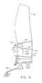
- Fig. 6 is a partial sectional view of the second fan stage of the gas turbine engine having an alternative configuration in accordance with the invention.
-
- Referring now to the drawings in detail, wherein identical numerals indicate the same elements throughout the figures, Fig. 1 depicts an exemplary turbofan
gas turbine engine 10 having afan section 12 which receives an inlet flow of ambient air represented byarrow 14.Fan section 12 preferably includes afirst stage 16 having a first row offan blades 18 and asecond stage 20 having a second row offan blades 22. In the typical bypass turbofan arrangement, firstrow fan blades 18 will rotate in an opposite direction from, or counter to, the rotation of secondrow fan blades 22. It will be appreciated thatfirst fan stage 16 andsecond fan stage 20 preferably are spaced a desired axial distance with respect to acenterline axis 24 extending throughgas turbine engine 10 so as to minimize any wake in the air flow therebetween. - A
high pressure rotor 26, also known herein as a middle core engine, is positioned downstream offan section 12, where it will be understood from Fig. 1 that the left side thereof is representative of an upstream side or direction and the right side thereof is representative of a downstream side or direction given the flow of air throughgas turbine engine 10. It will be understood thathigh pressure rotor 26 includes ahigh pressure compressor 28 which is rotatably driven to compress air enteringhigh pressure rotor 26 to a relatively high pressure, acombustor 30 which mixes fuel withair 14 pressurized byhigh pressure compressor 28 and ignited to generate combustion gases which flow downstream, and ahigh pressure turbine 32 which receives the combustion gases and is rotatably driven thereby.High pressure turbine 32, in turn, rotatably driveshigh pressure compressor 28 via a highpressure drive shaft 34 which interconnectshigh pressure turbine 32 andhigh pressure compressor 28. Preferably,high pressure rotor 26 is modular so that as a single unit it can be independently replaced with respect to other parts ofgas turbine engine 10. - It will be seen that a
booster compressor 36, which is preferably located upstream ofhigh pressure rotor 26, includes a first row ofbooster compressor blades 38 and a second row ofbooster compressor blades 40 interdigitated with first boostercompressor blade row 38.Booster compressor 36 is counter-rotatable, meaning that first boostercompressor blade row 38 rotates in a direction opposite that of second boostercompressor blade row 40.Gas turbine engine 10 is preferably designed such thatbooster compressor blades 40 andfan blades 22 ofsecond fan stage 20 rotate in a direction opposite that ofhigh pressure compressor 28 so as to reduce the sensitivity ofgas turbine engine 10 to airflow inlet distortion offan section 12, as well as reduce mutual sensitivity to rotating stall cells in the other rotors. Anoutlet guide van 42 may be provided betweensecond fan stage 20 andhigh pressure compressor 28 to assist in deswirling the air flow tohigh pressure compressor 28. - A counter-rotatable
low pressure turbine 44 positioned downstream ofhigh pressure turbine 32 expands the combustion gases flowing throughhigh pressure turbine 32 and functions to rotatably drivefirst fan stage 16 and first boostercompressor blade row 38 by means of a first or inner lowpressure drive shaft 46 and rotatably drivesecond fan stage 20 and second boostercompressor blade row 40 by means of a second or outer lowpressure drive shaft 48. - More specifically,
low pressure turbine 44 includes an annularouter drum rotor 50 rotatably mounted to first inner lowpressure drive shaft 46 by an aft low pressure innerconical extension 52.Outer drum rotor 50 further includes a plurality of first low pressureturbine blade rows 54 extending radially inwardly therefrom and axially spaced from each other. It will be seen thatouter drum rotor 50 is cantilevered off of afinal stage 56 of low pressureturbine blade rows 54 and is bolted to aft low pressure innerconical shaft extension 52. Low pressureinner drive shaft 46 is then seen to drivingly connectouter drum rotor 50 tofirst fan stage 16 and firstfan blade row 18 by means of a forward conicalinner shaft extension 58. First boostercompressor blade row 38 is then indirectly driven by low pressureinner drive shaft 46 due to ashaft 60 connectingfirst fan stage 16 thereto, causing first stagefan blade row 18 and first boostercompressor blade row 38 to rotate in the same direction. -
Low pressure turbine 44 also includes an annularinner drum rotor 62 which is rotatably mounted to second outer lowpressure drive shaft 48 by an aft low pressure outerconical shaft extension 64.Inner drum rotor 62 further includes a plurality of second low pressureturbine blade rows 66 extending radially outwardly therefrom and axially spaced from each other. It will be appreciated that first low pressureturbine blade rows 54 are preferably interdigitated with respect to second low pressureturbine blade rows 66. It will be seen thatinner drum rotor 62 is conventionally attached through afinal stage 68 of low pressureturbine blade rows 66 and is bolted to aft low pressure outerconical shaft extension 64. Low pressureouter drive shaft 48 is then seen to drivingly connectinner drum rotor 62 tosecond fan stage 18 and secondfan blade row 20 by means of a forward conicalouter shaft extension 70. As will be discussed in greater detail herein, second boostercompressor blade row 40 is also driven by low pressureouter drive shaft 48, causing second stagefan blade row 20 and second boostercompressor blade row 40 to rotate in the same direction, which is counter to the direction of rotation byfirst fan stage 16 and first boostercompressor blade row 38. - A flow path represented by an
arrow 72 forfan 12 is defined by afan casing 74 and ahub 76 for first fan stage 16 (see Fig. 2). It will be seen thatflow path 72 is then preferably divided upstream ofsecond fan stage 20, where an outer portion represented by anarrow 78 bypasses the rest of engine 10 (except for passing through second fan stage 20) and an inner portion represented byarrow 80 is directed intobooster compressor 36 and aninlet duct 82 tohigh pressure compressor 28. It will be appreciated that asplitter nose 84 is provided in order to divideflow path 72, which will be discussed in greater detail herein. In association withsplitter nose 84, an innerbypass platform member 86 and awall 88 positioned downstream thereof are provided so as to maintain abypass duct 90 withfan casing 74 through which outerflow path portion 78 flows. Similarly, awall 92 is connected tohub 76, and in conjunction withsplitter nose 84, a boosterinner platform member 94, and a boosterouter platform member 96, form inner flow path portion 80 (otherwise known herein as the booster flow path). - As best seen in Figs. 2 and 3,
second fan stage 18 preferably includes aconventional disk 98 having dovetails therein to retainfan blades 22. Disk 98 is connected to ashaft extension 100, which is in turn connected to forward conicalouter shaft extension 70. In this way,disk 98 andfan blades 22 are then driven by low pressureouter drive shaft 48. - In accordance with the present invention, it will be seen that each
fan blade 22 preferably includes boosterinner platform member 94 integral therewith so as to maintain an inner boundary forbooster flow path 80. Boosterouter platform member 96 is also preferably integral with eachfan blade 22 in order to form an outer boundary ofbooster flow path 80. In this way, aninner portion 102 of eachfan blade 22 which extends between inner and outerbooster platform members compressor blade 104 in second boostercompressor blade row 40 ofbooster compressor 36. - It is further seen that each
fan blade 22 preferably includes innerbypass platform member 86 integral therewith at a location radially outside of outerbooster platform member 96. In order to facilitate connection ofsplitter nose 84 with outerbooster platform member 96 and innerbypass platform member 86, aflange 106 is provided which joinsplatform members Flange 106 is then preferably connected tosplitter nose 84 by means of abolt 108 andswage nut 110. In this way, at least one additional spool or stage forbooster compressor 36 may be provided, whereby one or more rows ofcompressor blades 112 may extend radially inward fromsplitter nose 84 and rotate in accordance withfan blades 22. Of course,compressor blades 112 are designed so as to interface withwall 92. It will also be understood that such row ofcompressor blades 112 will be located upstream of first rowbooster compressor blades 38 so that rotates counter to firststage fan blades 18 andbooster compressor blades 38. - As seen in Fig. 6, it is also contemplated that an
additional compressor blade 114 be positioned between innerbooster platform member 94 and outerbooster platform member 96 adjacent innerfan blade portion 102 of at least certain desiredfan blades 22. It will be noted thatsuch compressor blades 114 preferably have a width less than innerfan blade portion 102. Accordingly, when leadingedge 116 ofcompressor blade 114 is positioned substantially in line with aleading edge 118 of innerfan blade portion 102, a trailingedge 120 ofcompressor blade 114 extends only partially toward trailingedge 122 of innerfan blade portion 102.
Claims (11)
- A counter-rotatable booster compressor assembly (36) for a gas turbine engine (10) having a counter-rotatable fan section (12) with a first fan blade row (18) connected to a first drive shaft (46) and a second fan blade row (22) axially spaced from said first fan blade row (18) and connected to a second drive shaft (48), said counter-rotatable booster compressor assembly (36) comprising:wherein a portion (102) of each fan blade (22) of said second fan blade row (22) extends through a flowpath (80) of said counter-rotatable booster compressor (36) so as to function as a compressor blade (104) in said second compressor blade row (40).(a) a first compressor blade row (38) connected to said first drive shaft (46); and(b) a second compressor blade row (40) interdigitated with said first compressor blade row (38) and connected to said second drive shaft (48);
- The counter-rotatable booster compressor assembly (36) of claim 1, further comprising:(a) a first platform member (94) integral with each said fan blade (22) of said second fan blade row (22) at a first location so as to form an inner flowpath for said counter-rotatable booster compressor (36); and(b) a second platform member (96) integral with each said fan blade (22) of said second fan blade row (22) at a second location so as to form an outer flowpath for said counter-rotatable booster compressor (36).
- The counter-rotatable booster compressor assembly (36) of claim 2, further comprising a third platform member (86) integral with each said fan blade (22) of said second fan blade row (22) at a third location so as to form an inner flowpath for said counter-rotatable fan section (12).
- The counter-rotatable booster compressor assembly (36) of claim 3, said second and third platform members (96,86) being joined together at an upstream end to form an upstream flange (106).
- The counter-rotatable booster compressor assembly (36) of claim 4, further comprising a booster spool upstream of said second fan blade row (22) connected to said upstream flange (106), said booster spool including at least one compressor blade (112) extending therefrom which rotates in accordance with said second fan blade row (22).
- The counter-rotatable booster compressor assembly (36) of claim 1, further comprising an outlet guide vane (42) positioned in said booster flowpath (80) downstream of said second fan blade row (22).
- The counter-rotatable booster compressor assembly (36) of claim 1, wherein said booster compressor (36) is located between said first and second fan blade rows (18,22).
- The counter-rotatable booster compressor assembly (36) of claim 1, further comprising a disk (98) for retaining said second fan blade row (22), wherein said disk (98) is connected to said second drive shaft (48).
- The counter-rotatable booster compressor assembly (36) of claim 2, further comprising an additional booster compressor blade (114) located adjacent to at least some of said fan blades (22) in said second fan blade row (22), said additional booster compressor blades (114) extending between and connected to said first and second platform members (94,96).
- The fan blade assembly of claim 9, wherein said additional booster compressor blades (114) have a width which is less than a width of said fan blade portions (102) functioning as a compressor blade (104).
- The fan blade assembly of claim 10, wherein a leading edge (116) of said additional booster compressor blades (114) is positioned substantially in line with a leading edge (118) for said fan blade portions (102) functioning as a compressor blade (104).
Applications Claiming Priority (2)
| Application Number | Priority Date | Filing Date | Title |
|---|---|---|---|
| US134172 | 2002-04-29 | ||
| US10/134,172 US6739120B2 (en) | 2002-04-29 | 2002-04-29 | Counterrotatable booster compressor assembly for a gas turbine engine |
Publications (2)
| Publication Number | Publication Date |
|---|---|
| EP1367250A1 true EP1367250A1 (en) | 2003-12-03 |
| EP1367250B1 EP1367250B1 (en) | 2014-01-01 |
Family
ID=29249156
Family Applications (1)
| Application Number | Title | Priority Date | Filing Date |
|---|---|---|---|
| EP03251104.0A Expired - Fee Related EP1367250B1 (en) | 2002-04-29 | 2003-02-25 | Counter-rotatable booster compressor assembly for a gas turbine engine |
Country Status (3)
| Country | Link |
|---|---|
| US (1) | US6739120B2 (en) |
| EP (1) | EP1367250B1 (en) |
| JP (1) | JP4204349B2 (en) |
Cited By (2)
| Publication number | Priority date | Publication date | Assignee | Title |
|---|---|---|---|---|
| EP1757796A2 (en) | 2005-08-22 | 2007-02-28 | Snecma | Compressor having a plurality of segments reconstructing an annular volume and thus separating the flow in a turbomachine |
| RU214996U1 (en) * | 2022-09-28 | 2022-11-23 | Общество с ограниченной ответственностью "РОСТОВСКИЙ ВОЗДУХОзаВОД" (ООО "РВЗ") | Mounting unit for fan blades |
Families Citing this family (62)
| Publication number | Priority date | Publication date | Assignee | Title |
|---|---|---|---|---|
| US6684626B1 (en) * | 2002-07-30 | 2004-02-03 | General Electric Company | Aircraft gas turbine engine with control vanes for counter rotating low pressure turbines |
| US6763652B2 (en) * | 2002-09-24 | 2004-07-20 | General Electric Company | Variable torque split aircraft gas turbine engine counter rotating low pressure turbines |
| US6763653B2 (en) * | 2002-09-24 | 2004-07-20 | General Electric Company | Counter rotating fan aircraft gas turbine engine with aft booster |
| US7100358B2 (en) * | 2004-07-16 | 2006-09-05 | Pratt & Whitney Canada Corp. | Turbine exhaust case and method of making |
| US7334392B2 (en) * | 2004-10-29 | 2008-02-26 | General Electric Company | Counter-rotating gas turbine engine and method of assembling same |
| US7296398B2 (en) * | 2004-10-29 | 2007-11-20 | General Electric Company | Counter-rotating turbine engine and method of assembling same |
| US7409819B2 (en) * | 2004-10-29 | 2008-08-12 | General Electric Company | Gas turbine engine and method of assembling same |
| US7269938B2 (en) * | 2004-10-29 | 2007-09-18 | General Electric Company | Counter-rotating gas turbine engine and method of assembling same |
| US7334981B2 (en) * | 2004-10-29 | 2008-02-26 | General Electric Company | Counter-rotating gas turbine engine and method of assembling same |
| US7186073B2 (en) * | 2004-10-29 | 2007-03-06 | General Electric Company | Counter-rotating gas turbine engine and method of assembling same |
| US7195447B2 (en) * | 2004-10-29 | 2007-03-27 | General Electric Company | Gas turbine engine and method of assembling same |
| US7290386B2 (en) | 2004-10-29 | 2007-11-06 | General Electric Company | Counter-rotating gas turbine engine and method of assembling same |
| US7195446B2 (en) * | 2004-10-29 | 2007-03-27 | General Electric Company | Counter-rotating turbine engine and method of assembling same |
| US7458202B2 (en) * | 2004-10-29 | 2008-12-02 | General Electric Company | Lubrication system for a counter-rotating turbine engine and method of assembling same |
| US7594388B2 (en) * | 2005-06-06 | 2009-09-29 | General Electric Company | Counterrotating turbofan engine |
| US7726113B2 (en) * | 2005-10-19 | 2010-06-01 | General Electric Company | Gas turbine engine assembly and methods of assembling same |
| US7493753B2 (en) * | 2005-10-19 | 2009-02-24 | General Electric Company | Gas turbine engine assembly and methods of assembling same |
| US7526913B2 (en) * | 2005-10-19 | 2009-05-05 | General Electric Company | Gas turbine engine assembly and methods of assembling same |
| US7490461B2 (en) * | 2005-10-19 | 2009-02-17 | General Electric Company | Gas turbine engine assembly and methods of assembling same |
| US7603844B2 (en) * | 2005-10-19 | 2009-10-20 | General Electric Company | Gas turbine engine assembly and methods of assembling same |
| US7752836B2 (en) * | 2005-10-19 | 2010-07-13 | General Electric Company | Gas turbine assembly and methods of assembling same |
| US7493754B2 (en) * | 2005-10-19 | 2009-02-24 | General Electric Company | Gas turbine engine assembly and methods of assembling same |
| US7685808B2 (en) * | 2005-10-19 | 2010-03-30 | General Electric Company | Gas turbine engine assembly and methods of assembling same |
| US7490460B2 (en) * | 2005-10-19 | 2009-02-17 | General Electric Company | Gas turbine engine assembly and methods of assembling same |
| US7513103B2 (en) * | 2005-10-19 | 2009-04-07 | General Electric Company | Gas turbine engine assembly and methods of assembling same |
| US8016561B2 (en) * | 2006-07-11 | 2011-09-13 | General Electric Company | Gas turbine engine fan assembly and method for assembling to same |
| US7694505B2 (en) * | 2006-07-31 | 2010-04-13 | General Electric Company | Gas turbine engine assembly and method of assembling same |
| US20080075590A1 (en) * | 2006-09-27 | 2008-03-27 | Thomas Ory Moniz | Gas turbine engine assembly and method of assembling same |
| US7832193B2 (en) * | 2006-10-27 | 2010-11-16 | General Electric Company | Gas turbine engine assembly and methods of assembling same |
| US7841165B2 (en) * | 2006-10-31 | 2010-11-30 | General Electric Company | Gas turbine engine assembly and methods of assembling same |
| US7926259B2 (en) * | 2006-10-31 | 2011-04-19 | General Electric Company | Turbofan engine assembly and method of assembling same |
| US7966806B2 (en) * | 2006-10-31 | 2011-06-28 | General Electric Company | Turbofan engine assembly and method of assembling same |
| RU2349503C1 (en) * | 2007-07-18 | 2009-03-20 | Владимир Дмитриевич Гречишников | Rotor |
| US8708643B2 (en) * | 2007-08-14 | 2014-04-29 | General Electric Company | Counter-rotatable fan gas turbine engine with axial flow positive displacement worm gas generator |
| US8590286B2 (en) * | 2007-12-05 | 2013-11-26 | United Technologies Corp. | Gas turbine engine systems involving tip fans |
| US8015798B2 (en) * | 2007-12-13 | 2011-09-13 | United Technologies Corporation | Geared counter-rotating gas turbofan engine |
| US8292570B2 (en) * | 2008-01-25 | 2012-10-23 | United Technologies Corporation | Low pressure turbine with counter-rotating drives for single spool |
| EP2123884B1 (en) * | 2008-05-13 | 2015-03-04 | Rolls-Royce Corporation | Dual clutch arrangement |
| US20100005810A1 (en) * | 2008-07-11 | 2010-01-14 | Rob Jarrell | Power transmission among shafts in a turbine engine |
| US8480527B2 (en) * | 2008-08-27 | 2013-07-09 | Rolls-Royce Corporation | Gearing arrangement |
| US8166748B2 (en) * | 2008-11-21 | 2012-05-01 | General Electric Company | Gas turbine engine booster having rotatable radially inwardly extending blades and non-rotatable vanes |
| US8011877B2 (en) * | 2008-11-24 | 2011-09-06 | General Electric Company | Fiber composite reinforced aircraft gas turbine engine drums with radially inwardly extending blades |
| US8075438B2 (en) * | 2008-12-11 | 2011-12-13 | Rolls-Royce Corporation | Apparatus and method for transmitting a rotary input into counter-rotating outputs |
| US8021267B2 (en) * | 2008-12-11 | 2011-09-20 | Rolls-Royce Corporation | Coupling assembly |
| CA2748737C (en) * | 2008-12-31 | 2017-01-24 | Rolls-Royce North American Technologies, Inc. | Variable pressure ratio compressor |
| US8375695B2 (en) * | 2009-06-30 | 2013-02-19 | General Electric Company | Aircraft gas turbine engine counter-rotatable generator |
| FR2948973B1 (en) * | 2009-08-05 | 2011-10-14 | Snecma | PROPELLER HUB WITH VARIABLE SHAFT BLADES |
| US8063528B2 (en) * | 2009-12-18 | 2011-11-22 | General Electric Company | Counter-rotatable generator |
| US9410427B2 (en) * | 2012-06-05 | 2016-08-09 | United Technologies Corporation | Compressor power and torque transmitting hub |
| US9752500B2 (en) * | 2013-03-14 | 2017-09-05 | Pratt & Whitney Canada Corp. | Gas turbine engine with transmission and method of adjusting rotational speed |
| US10669947B2 (en) | 2016-07-11 | 2020-06-02 | Raytheon Technologies Corporation | Geared gas turbine engine |
| US10557373B2 (en) * | 2017-12-05 | 2020-02-11 | United Technologies Corporation | Low profile embedded blade tip clearance probe assembly |
| US10641595B2 (en) * | 2018-04-09 | 2020-05-05 | United Technologies Corporation | Low profile triaxial blade tip clearance probe assembly with driven guard |
| US11143142B2 (en) | 2018-08-01 | 2021-10-12 | United Technologies Corporation | Adaptive engine with boost spool |
| US11028778B2 (en) | 2018-09-27 | 2021-06-08 | Pratt & Whitney Canada Corp. | Engine with start assist |
| US11156097B2 (en) | 2019-02-20 | 2021-10-26 | General Electric Company | Turbomachine having an airflow management assembly |
| US11073088B2 (en) | 2019-02-20 | 2021-07-27 | General Electric Company | Gearbox mounting in a turbomachine |
| US11021970B2 (en) | 2019-02-20 | 2021-06-01 | General Electric Company | Turbomachine with alternatingly spaced rotor blades |
| US11085515B2 (en) | 2019-02-20 | 2021-08-10 | General Electric Company | Gearbox coupling in a turbomachine |
| US11753939B2 (en) | 2019-02-20 | 2023-09-12 | General Electric Company | Turbomachine with alternatingly spaced rotor blades |
| GB202114773D0 (en) | 2021-10-15 | 2021-12-01 | Rolls Royce Plc | Bladed disc |
| US20240110504A1 (en) * | 2022-09-29 | 2024-04-04 | General Electric Company | Counter-rotating gas turbine engines including turbine sections with separable torque frames |
Citations (5)
| Publication number | Priority date | Publication date | Assignee | Title |
|---|---|---|---|---|
| US4790133A (en) * | 1986-08-29 | 1988-12-13 | General Electric Company | High bypass ratio counterrotating turbofan engine |
| US4860537A (en) * | 1986-08-29 | 1989-08-29 | Brandt, Inc. | High bypass ratio counterrotating gearless front fan engine |
| EP0631041A1 (en) * | 1993-06-18 | 1994-12-28 | General Electric Company | Rotatable turbine frame |
| US5388964A (en) * | 1993-09-14 | 1995-02-14 | General Electric Company | Hybrid rotor blade |
| US6158210A (en) * | 1998-12-03 | 2000-12-12 | General Electric Company | Gear driven booster |
Family Cites Families (12)
| Publication number | Priority date | Publication date | Assignee | Title |
|---|---|---|---|---|
| FR1555814A (en) * | 1967-12-12 | 1969-01-31 | ||
| GB1305302A (en) * | 1970-04-28 | 1973-01-31 | ||
| DE2149619A1 (en) * | 1971-10-05 | 1973-04-19 | Motoren Turbinen Union | TURBINE JET FOR VERTICAL OR SHORT-STARTING OR LANDING AIRPLANES |
| US3903690A (en) * | 1973-02-12 | 1975-09-09 | Gen Electric | Turbofan engine lubrication means |
| GB1484898A (en) * | 1974-09-11 | 1977-09-08 | Rolls Royce | Ducted fan gas turbine engine |
| US4791783A (en) * | 1981-11-27 | 1988-12-20 | General Electric Company | Convertible aircraft engine |
| GB2195712B (en) | 1986-10-08 | 1990-08-29 | Rolls Royce Plc | A turbofan gas turbine engine |
| US4976102A (en) | 1988-05-09 | 1990-12-11 | General Electric Company | Unducted, counterrotating gearless front fan engine |
| US5345760A (en) | 1993-02-05 | 1994-09-13 | General Electric Company | Turboprop booster |
| US5307622A (en) | 1993-08-02 | 1994-05-03 | General Electric Company | Counterrotating turbine support assembly |
| US6220012B1 (en) | 1999-05-10 | 2001-04-24 | General Electric Company | Booster recirculation passageway and methods for recirculating air |
| USH2032H1 (en) | 1999-10-01 | 2002-07-02 | The United States Of America As Represented By The Secretary Of The Air Force | Integrated fan-core twin spool counter-rotating turbofan gas turbine engine |
-
2002
- 2002-04-29 US US10/134,172 patent/US6739120B2/en not_active Expired - Fee Related
-
2003
- 2003-02-25 EP EP03251104.0A patent/EP1367250B1/en not_active Expired - Fee Related
- 2003-02-28 JP JP2003052194A patent/JP4204349B2/en not_active Expired - Fee Related
Patent Citations (5)
| Publication number | Priority date | Publication date | Assignee | Title |
|---|---|---|---|---|
| US4790133A (en) * | 1986-08-29 | 1988-12-13 | General Electric Company | High bypass ratio counterrotating turbofan engine |
| US4860537A (en) * | 1986-08-29 | 1989-08-29 | Brandt, Inc. | High bypass ratio counterrotating gearless front fan engine |
| EP0631041A1 (en) * | 1993-06-18 | 1994-12-28 | General Electric Company | Rotatable turbine frame |
| US5388964A (en) * | 1993-09-14 | 1995-02-14 | General Electric Company | Hybrid rotor blade |
| US6158210A (en) * | 1998-12-03 | 2000-12-12 | General Electric Company | Gear driven booster |
Cited By (4)
| Publication number | Priority date | Publication date | Assignee | Title |
|---|---|---|---|---|
| EP1757796A2 (en) | 2005-08-22 | 2007-02-28 | Snecma | Compressor having a plurality of segments reconstructing an annular volume and thus separating the flow in a turbomachine |
| EP1757796A3 (en) * | 2005-08-22 | 2016-02-10 | Snecma | Compressor having a plurality of segments reconstructing an annular volume and thus separating the flow in a turbomachine |
| RU214996U1 (en) * | 2022-09-28 | 2022-11-23 | Общество с ограниченной ответственностью "РОСТОВСКИЙ ВОЗДУХОзаВОД" (ООО "РВЗ") | Mounting unit for fan blades |
| RU2787424C1 (en) * | 2022-09-28 | 2023-01-09 | Общество с ограниченной ответственностью "РОСТОВСКИЙ ВОЗДУХОзаВОД" (ООО "РВЗ") | Mounting unit for fan blades |
Also Published As
| Publication number | Publication date |
|---|---|
| US20030200741A1 (en) | 2003-10-30 |
| EP1367250B1 (en) | 2014-01-01 |
| JP2003322027A (en) | 2003-11-14 |
| JP4204349B2 (en) | 2009-01-07 |
| US6739120B2 (en) | 2004-05-25 |
Similar Documents
| Publication | Publication Date | Title |
|---|---|---|
| EP1367250B1 (en) | Counter-rotatable booster compressor assembly for a gas turbine engine | |
| EP1365154B1 (en) | Counterrotatable booster compressor assembly for a gas turbine engine | |
| JP4588306B2 (en) | Aircraft gas turbine engine with non-intermeshing counter-rotating low pressure turbine | |
| JP4346375B2 (en) | Aircraft gas turbine engine with control vanes for counter rotating low pressure turbine | |
| US6763654B2 (en) | Aircraft gas turbine engine having variable torque split counter rotating low pressure turbines and booster aft of counter rotating fans | |
| US6763653B2 (en) | Counter rotating fan aircraft gas turbine engine with aft booster | |
| EP1403485B1 (en) | Gas turbine engine with low pressure turbine comprising counter rotatable low pressure inner and outer shaft turbines | |
| EP1626002B1 (en) | Gas turbine engine turbine assembly | |
| CA2567940C (en) | Methods and apparatuses for gas turbine engines | |
| US20090162187A1 (en) | Counter-rotating compressor case and assembly method for tip turbine engine | |
| US20090145101A1 (en) | Particle separator for tip turbine engine | |
| US20080219833A1 (en) | Inducer for a Fan Blade of a Tip Turbine Engine | |
| US20070240424A1 (en) | Gas turbine engine having bypass ducts | |
| US20200096002A1 (en) | Axial compressor |
Legal Events
| Date | Code | Title | Description |
|---|---|---|---|
| PUAI | Public reference made under article 153(3) epc to a published international application that has entered the european phase |
Free format text: ORIGINAL CODE: 0009012 |
|
| AK | Designated contracting states |
Kind code of ref document: A1 Designated state(s): AT BE BG CH CY CZ DE DK EE ES FI FR GB GR HU IE IT LI LU MC NL PT SE SI SK TR |
|
| AX | Request for extension of the european patent |
Extension state: AL LT LV MK RO |
|
| 17P | Request for examination filed |
Effective date: 20040603 |
|
| 17Q | First examination report despatched |
Effective date: 20040714 |
|
| AKX | Designation fees paid |
Designated state(s): DE FR GB IT |
|
| GRAP | Despatch of communication of intention to grant a patent |
Free format text: ORIGINAL CODE: EPIDOSNIGR1 |
|
| INTG | Intention to grant announced |
Effective date: 20130801 |
|
| GRAS | Grant fee paid |
Free format text: ORIGINAL CODE: EPIDOSNIGR3 |
|
| GRAA | (expected) grant |
Free format text: ORIGINAL CODE: 0009210 |
|
| AK | Designated contracting states |
Kind code of ref document: B1 Designated state(s): DE FR GB IT |
|
| REG | Reference to a national code |
Ref country code: GB Ref legal event code: FG4D |
|
| REG | Reference to a national code |
Ref country code: DE Ref legal event code: R096 Ref document number: 60345536 Country of ref document: DE Effective date: 20140220 |
|
| REG | Reference to a national code |
Ref country code: DE Ref legal event code: R097 Ref document number: 60345536 Country of ref document: DE |
|
| PLBE | No opposition filed within time limit |
Free format text: ORIGINAL CODE: 0009261 |
|
| STAA | Information on the status of an ep patent application or granted ep patent |
Free format text: STATUS: NO OPPOSITION FILED WITHIN TIME LIMIT |
|
| 26N | No opposition filed |
Effective date: 20141002 |
|
| REG | Reference to a national code |
Ref country code: DE Ref legal event code: R097 Ref document number: 60345536 Country of ref document: DE Effective date: 20141002 |
|
| REG | Reference to a national code |
Ref country code: FR Ref legal event code: PLFP Year of fee payment: 13 |
|
| PGFP | Annual fee paid to national office [announced via postgrant information from national office to epo] |
Ref country code: IT Payment date: 20150225 Year of fee payment: 13 Ref country code: DE Payment date: 20150226 Year of fee payment: 13 |
|
| PGFP | Annual fee paid to national office [announced via postgrant information from national office to epo] |
Ref country code: FR Payment date: 20150217 Year of fee payment: 13 Ref country code: GB Payment date: 20150226 Year of fee payment: 13 |
|
| REG | Reference to a national code |
Ref country code: DE Ref legal event code: R119 Ref document number: 60345536 Country of ref document: DE |
|
| GBPC | Gb: european patent ceased through non-payment of renewal fee |
Effective date: 20160225 |
|
| REG | Reference to a national code |
Ref country code: FR Ref legal event code: ST Effective date: 20161028 |
|
| PG25 | Lapsed in a contracting state [announced via postgrant information from national office to epo] |
Ref country code: IT Free format text: LAPSE BECAUSE OF NON-PAYMENT OF DUE FEES Effective date: 20160225 |
|
| PG25 | Lapsed in a contracting state [announced via postgrant information from national office to epo] |
Ref country code: FR Free format text: LAPSE BECAUSE OF NON-PAYMENT OF DUE FEES Effective date: 20160229 Ref country code: DE Free format text: LAPSE BECAUSE OF NON-PAYMENT OF DUE FEES Effective date: 20160901 Ref country code: GB Free format text: LAPSE BECAUSE OF NON-PAYMENT OF DUE FEES Effective date: 20160225 |