EP1367236A1 - Flow divider device for air manifolds adapted to generate turbulent flows in combustion chambers - Google Patents
Flow divider device for air manifolds adapted to generate turbulent flows in combustion chambers Download PDFInfo
- Publication number
- EP1367236A1 EP1367236A1 EP03012303A EP03012303A EP1367236A1 EP 1367236 A1 EP1367236 A1 EP 1367236A1 EP 03012303 A EP03012303 A EP 03012303A EP 03012303 A EP03012303 A EP 03012303A EP 1367236 A1 EP1367236 A1 EP 1367236A1
- Authority
- EP
- European Patent Office
- Prior art keywords
- air
- throttle
- port
- fuel
- channels
- Prior art date
- Legal status (The legal status is an assumption and is not a legal conclusion. Google has not performed a legal analysis and makes no representation as to the accuracy of the status listed.)
- Granted
Links
Images




Classifications
-
- F—MECHANICAL ENGINEERING; LIGHTING; HEATING; WEAPONS; BLASTING
- F02—COMBUSTION ENGINES; HOT-GAS OR COMBUSTION-PRODUCT ENGINE PLANTS
- F02M—SUPPLYING COMBUSTION ENGINES IN GENERAL WITH COMBUSTIBLE MIXTURES OR CONSTITUENTS THEREOF
- F02M35/00—Combustion-air cleaners, air intakes, intake silencers, or induction systems specially adapted for, or arranged on, internal-combustion engines
- F02M35/10—Air intakes; Induction systems
- F02M35/10209—Fluid connections to the air intake system; their arrangement of pipes, valves or the like
- F02M35/10216—Fuel injectors; Fuel pipes or rails; Fuel pumps or pressure regulators
-
- F—MECHANICAL ENGINEERING; LIGHTING; HEATING; WEAPONS; BLASTING
- F02—COMBUSTION ENGINES; HOT-GAS OR COMBUSTION-PRODUCT ENGINE PLANTS
- F02B—INTERNAL-COMBUSTION PISTON ENGINES; COMBUSTION ENGINES IN GENERAL
- F02B31/00—Modifying induction systems for imparting a rotation to the charge in the cylinder
- F02B31/08—Modifying induction systems for imparting a rotation to the charge in the cylinder having multiple air inlets
- F02B31/085—Modifying induction systems for imparting a rotation to the charge in the cylinder having multiple air inlets having two inlet valves
-
- F—MECHANICAL ENGINEERING; LIGHTING; HEATING; WEAPONS; BLASTING
- F02—COMBUSTION ENGINES; HOT-GAS OR COMBUSTION-PRODUCT ENGINE PLANTS
- F02M—SUPPLYING COMBUSTION ENGINES IN GENERAL WITH COMBUSTIBLE MIXTURES OR CONSTITUENTS THEREOF
- F02M35/00—Combustion-air cleaners, air intakes, intake silencers, or induction systems specially adapted for, or arranged on, internal-combustion engines
- F02M35/10—Air intakes; Induction systems
- F02M35/10006—Air intakes; Induction systems characterised by the position of elements of the air intake system in direction of the air intake flow, i.e. between ambient air inlet and supply to the combustion chamber
- F02M35/10026—Plenum chambers
- F02M35/10032—Plenum chambers specially shaped or arranged connecting duct between carburettor or air inlet duct and the plenum chamber; specially positioned carburettors or throttle bodies with respect to the plenum chamber
-
- F—MECHANICAL ENGINEERING; LIGHTING; HEATING; WEAPONS; BLASTING
- F02—COMBUSTION ENGINES; HOT-GAS OR COMBUSTION-PRODUCT ENGINE PLANTS
- F02M—SUPPLYING COMBUSTION ENGINES IN GENERAL WITH COMBUSTIBLE MIXTURES OR CONSTITUENTS THEREOF
- F02M35/00—Combustion-air cleaners, air intakes, intake silencers, or induction systems specially adapted for, or arranged on, internal-combustion engines
- F02M35/10—Air intakes; Induction systems
- F02M35/10006—Air intakes; Induction systems characterised by the position of elements of the air intake system in direction of the air intake flow, i.e. between ambient air inlet and supply to the combustion chamber
- F02M35/10078—Connections of intake systems to the engine
- F02M35/10085—Connections of intake systems to the engine having a connecting piece, e.g. a flange, between the engine and the air intake being foreseen with a throttle valve, fuel injector, mixture ducts or the like
-
- F—MECHANICAL ENGINEERING; LIGHTING; HEATING; WEAPONS; BLASTING
- F02—COMBUSTION ENGINES; HOT-GAS OR COMBUSTION-PRODUCT ENGINE PLANTS
- F02M—SUPPLYING COMBUSTION ENGINES IN GENERAL WITH COMBUSTIBLE MIXTURES OR CONSTITUENTS THEREOF
- F02M35/00—Combustion-air cleaners, air intakes, intake silencers, or induction systems specially adapted for, or arranged on, internal-combustion engines
- F02M35/10—Air intakes; Induction systems
- F02M35/10242—Devices or means connected to or integrated into air intakes; Air intakes combined with other engine or vehicle parts
- F02M35/10255—Arrangements of valves; Multi-way valves
-
- F—MECHANICAL ENGINEERING; LIGHTING; HEATING; WEAPONS; BLASTING
- F02—COMBUSTION ENGINES; HOT-GAS OR COMBUSTION-PRODUCT ENGINE PLANTS
- F02M—SUPPLYING COMBUSTION ENGINES IN GENERAL WITH COMBUSTIBLE MIXTURES OR CONSTITUENTS THEREOF
- F02M35/00—Combustion-air cleaners, air intakes, intake silencers, or induction systems specially adapted for, or arranged on, internal-combustion engines
- F02M35/10—Air intakes; Induction systems
- F02M35/10242—Devices or means connected to or integrated into air intakes; Air intakes combined with other engine or vehicle parts
- F02M35/10288—Air intakes combined with another engine part, e.g. cylinder head cover or being cast in one piece with the exhaust manifold, cylinder head or engine block
-
- F—MECHANICAL ENGINEERING; LIGHTING; HEATING; WEAPONS; BLASTING
- F02—COMBUSTION ENGINES; HOT-GAS OR COMBUSTION-PRODUCT ENGINE PLANTS
- F02M—SUPPLYING COMBUSTION ENGINES IN GENERAL WITH COMBUSTIBLE MIXTURES OR CONSTITUENTS THEREOF
- F02M35/00—Combustion-air cleaners, air intakes, intake silencers, or induction systems specially adapted for, or arranged on, internal-combustion engines
- F02M35/10—Air intakes; Induction systems
- F02M35/104—Intake manifolds
- F02M35/108—Intake manifolds with primary and secondary intake passages
-
- F—MECHANICAL ENGINEERING; LIGHTING; HEATING; WEAPONS; BLASTING
- F02—COMBUSTION ENGINES; HOT-GAS OR COMBUSTION-PRODUCT ENGINE PLANTS
- F02M—SUPPLYING COMBUSTION ENGINES IN GENERAL WITH COMBUSTIBLE MIXTURES OR CONSTITUENTS THEREOF
- F02M35/00—Combustion-air cleaners, air intakes, intake silencers, or induction systems specially adapted for, or arranged on, internal-combustion engines
- F02M35/10—Air intakes; Induction systems
- F02M35/104—Intake manifolds
- F02M35/112—Intake manifolds for engines with cylinders all in one line
-
- F—MECHANICAL ENGINEERING; LIGHTING; HEATING; WEAPONS; BLASTING
- F02—COMBUSTION ENGINES; HOT-GAS OR COMBUSTION-PRODUCT ENGINE PLANTS
- F02D—CONTROLLING COMBUSTION ENGINES
- F02D9/00—Controlling engines by throttling air or fuel-and-air induction conduits or exhaust conduits
- F02D9/08—Throttle valves specially adapted therefor; Arrangements of such valves in conduits
- F02D9/10—Throttle valves specially adapted therefor; Arrangements of such valves in conduits having pivotally-mounted flaps
-
- Y—GENERAL TAGGING OF NEW TECHNOLOGICAL DEVELOPMENTS; GENERAL TAGGING OF CROSS-SECTIONAL TECHNOLOGIES SPANNING OVER SEVERAL SECTIONS OF THE IPC; TECHNICAL SUBJECTS COVERED BY FORMER USPC CROSS-REFERENCE ART COLLECTIONS [XRACs] AND DIGESTS
- Y02—TECHNOLOGIES OR APPLICATIONS FOR MITIGATION OR ADAPTATION AGAINST CLIMATE CHANGE
- Y02T—CLIMATE CHANGE MITIGATION TECHNOLOGIES RELATED TO TRANSPORTATION
- Y02T10/00—Road transport of goods or passengers
- Y02T10/10—Internal combustion engine [ICE] based vehicles
- Y02T10/12—Improving ICE efficiencies
Definitions
- the present invention relates to a device for air manifolds adapted to create turbulent flows in combustion chambers.
- Air manifolds adapted to take in air from the external atmosphere and to supply this air to the combustion chambers are well known in the prior art. These manifolds have a number of ducts (commonly called runners) equal to the number of cylinders that need to be supplied with air, or with an air/fuel mixture, depending on whether the combustion chambers have a direct fuel injection system or there is air/fuel premixing in the engine prior to entry into the combustion chamber via a respective delivery valve.
- runners commonly called runners
- the flow of air, or of air mixed with fuel, injected is controlled by means of a regulation system controlled by the accelerator pedal of the motor vehicle.
- a regulation system controlled by the accelerator pedal of the motor vehicle.
- the greater the power requirement the greater the opening of the throttle will be so that a greater quantity of air (or air/fuel mixture) can be injected into the combustion chamber.
- the object of the present invention is therefore to provide an air, or air/fuel, supply system free from the drawbacks discussed above.
- the invention therefore relates to a device for air manifolds according to the characteristic features claimed in claim 1.
- an air unit is shown by 10 and comprises an air manifold 11 and a flow divider device 12 secured to one another by means of respective flanges 11 12a bearing on one another and clamped together by a plurality of bolts 13 (Fig. 1).
- the air manifold 11 further comprises, in a conventional manner, a duct 11b for the intake of air from outside in the direction of the arrow F1, and a main body 11c wound in a spiral (to increase the air turbulence) according to the turns of a plurality of runners 14 whose number is equal to the number of combustion chambers (not shown). In this case, there are four runners, so that the air unit 10 is able to supply a four-cylinder engine (not shown).
- the device 12 comprises a main body 15 obtained, for instance, by fusion of a light alloy, which in turn comprises a plurality of runners 16 equal in number to the number of runners 14. Since, as mentioned above, the flange 12a of the device 12 is clamped to the flange 11a of the air manifold 11, each runner 16 has to be seen as the continuation of the respective runner 14.
- the device 12 comprises a further flange 12b, disposed on the opposite side with respect to the main body 15, which is adapted to secure the unit 10 to the head (not shown) of an engine.
- the main body 15 and the two flanges 12a, 12b are, moreover, also preferably provided in one piece.
- each runner 16 has a respective longitudinal baffle 17.
- Each longitudinal baffle 17 extends between the two flanges 12a and 12b and is also preferably obtained rigidly with the other members of the device 12.
- each baffle 17 divides the respective runner 16 longitudinally into two channels 18 and 19 having a substantially identical cross-section.
- Each channel 18, 19, as will be described in further detail below, has a different function (see below).
- the channel 18 comprises a respective throttle 20 adapted to be rotated by a mechanism that will be described in further detail below (see below).
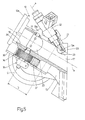
- each runner 16 is provided with a respective seat 21 adapted to house a respective injector 22 (Figs. 3 to 5) supplied with petrol by a fuel distribution system 22a (Fig. 5).
- Each seat 21 communicates, moreover, with the respective channel 16 via an aperture 16a (Figs. 5, 6).
- the axis (a) of the seat 21 (and therefore of the injector 22) is inclined with respect to an axis (b) of longitudinal symmetry of the respective runner 16.
- the seat 21 and the injector 22 are disposed astride the respective baffle 17.
- the baffle 17 is provided with a port 23 at the location of the opening 16a of the seat 20 communicating with the runner 16.
- the throttle 20 divides the flow of air in the channel 18, whose air does not provide the air/fuel mixture with a swirl movement.
- the aureole 24 extends along the whole perimeter of the throttle 20 and there should preferably be a "coverage factor" (k) varying between 0.83 and 0.9; the term “coverage factor” means the ratio between the surface area of the throttle 20 and the surface area of the transverse section of the channel 18.
- the throttle 20 is always upstream (with respect to the direction of flow of the air from the air manifold 11 to the engine head) of the port 23 and the opening 16a through which the fuel is injected.
- each throttle 20 must be mounted in a position close to the respective port 23.
- its surface facing the head of the engine must be disposed at a distance of between 2 and 5 mm, preferably 3 mm, from the closest edge of the port 23 which brings the two channels 18, 19 into communication.
- the distance D between the axis (c) of the throttle 20 and the closest edge of the port 23 must be between 2 and 5 mm, preferably 3 mm.
- the surface area of the port must be between 230 and 270 mm 2 , and, preferably, should not exceed 250 mm 2 .
- each throttle 20 is secured to a respective spindle 31 by means of two screws 32.
- the spindle 31 is supported by a pair of bearings 33, 34 (Fig. 9) and by a support member 35.
- Each bearing 33 is housed in a seat 33a provided in the respective channel 18.
- each toothed wheel 36 is contained in a respective casing 38 which is closed by a plate 39 in turn bearing on and screwed to two lugs 40, 41 (Figs. 4 and 5) which project from the outer surface of each runner 16.
- each plate 39 further comprises two through holes 42, 43 which make it possible to secure, by means of screws (not shown), the respective casing 38 containing, as mentioned above, a respective toothed wheel 36.
- the rack rod 37 is moved in translation by an electric motor unit 50 in the directions shown by the double arrow F2 in order to open (or close) the channels 18 by means of the throttles 20, depending on the driving conditions set by the driver by means of the accelerator pedal (not shown) and an electronic control unit (not shown).
- the electronic control unit converts the signal received from the accelerator and supplies it to each throttle 20.
- the rack rod 37 is, moreover, housed partially in the casing 38.
- the rack mechanism 30 causes the movement in translation of the rack rod 37 in the directions shown by the double arrow F2. Since the teeth 37a (Fig. 9) of the rack rod 37 are meshed with the teeth 36a of the toothed wheel 36, a translation of this rack rod 37 causes the spindle 31 to rotate about the axis (c) (Figs. 5, 9) which, as mentioned above, is supported by the bearings 33, 34, the support member 35 and the plate 39.
- each channel 18 is completely closed by the respective throttle 20, apart from the aureole 24, which continues to allow the passage of a certain quantity of washing air.
- the mechanism 30 causes the opening of the throttles 20 so as to enable the introduction of a greater quantity of air/petrol mixture into the combustion chambers.
- the rack mechanism 30, and in particular the actuation of the motor unit 40, is controlled and commanded by an electronic control unit (not shown).
Landscapes
- Engineering & Computer Science (AREA)
- Chemical & Material Sciences (AREA)
- Combustion & Propulsion (AREA)
- Mechanical Engineering (AREA)
- General Engineering & Computer Science (AREA)
- Control Of Throttle Valves Provided In The Intake System Or In The Exhaust System (AREA)
- Fuel-Injection Apparatus (AREA)
- Cylinder Crankcases Of Internal Combustion Engines (AREA)
- Output Control And Ontrol Of Special Type Engine (AREA)
Abstract
Description
- The present invention relates to a device for air manifolds adapted to create turbulent flows in combustion chambers.
- Air manifolds adapted to take in air from the external atmosphere and to supply this air to the combustion chambers are well known in the prior art. These manifolds have a number of ducts (commonly called runners) equal to the number of cylinders that need to be supplied with air, or with an air/fuel mixture, depending on whether the combustion chambers have a direct fuel injection system or there is air/fuel premixing in the engine prior to entry into the combustion chamber via a respective delivery valve.
- The flow of air, or of air mixed with fuel, injected is controlled by means of a regulation system controlled by the accelerator pedal of the motor vehicle. In a conventional manner, the greater the power requirement, the greater the opening of the throttle will be so that a greater quantity of air (or air/fuel mixture) can be injected into the combustion chamber.
- One of the problems of these conventional systems is that an optimum regulation of the supply flow to the cylinders is not obtained, especially at a low number of revolutions of the engine. Moreover, current systems do not ensure turbulent flows of the swirl type within the combustion chambers in an optimum manner.
- The object of the present invention is therefore to provide an air, or air/fuel, supply system free from the drawbacks discussed above.
- The invention therefore relates to a device for air manifolds according to the characteristic features claimed in claim 1.
- The present invention will be described below with reference to the accompanying drawings, which show a non-limiting embodiment thereof, and in which:
- Fig. 1 is a three-dimensional view of a flow divider device of the present invention associated with an air manifold for internal combustion engines; the assembly of the air manifold and the flow divider device provides an air unit;
- Fig. 2 is a further three-dimensional view solely of the air manifold of Fig. 1;
- Fig. 3 is a three-dimensional view solely of the flow divider device of the present invention;
- Fig. 4 is a side view of the flow divider device of Fig.3;
- Fig. 5 is a longitudinal section through the flow divider device of Fig. 4;
- Fig. 6 is a front view, on an enlarged scale, of the flow divider device of Fig. 3;
- Fig. 7 is a further overall view of the flow divider device of Fig. 3;
- Fig. 8 shows some details of the flow divider device of Fig. 3;
- Fig. 9 shows a throttle whose rotation about an axis is achieved by means of a novel rack mechanism.
-
- In Fig. 1, an air unit is shown by 10 and comprises an
air manifold 11 and aflow divider device 12 secured to one another by means ofrespective flanges 11 12a bearing on one another and clamped together by a plurality of bolts 13 (Fig. 1). - It will be appreciated that only structural details essential for comprehension of the present invention will be described and numbered in the following description.
- The
air manifold 11 further comprises, in a conventional manner, aduct 11b for the intake of air from outside in the direction of the arrow F1, and amain body 11c wound in a spiral (to increase the air turbulence) according to the turns of a plurality ofrunners 14 whose number is equal to the number of combustion chambers (not shown). In this case, there are four runners, so that theair unit 10 is able to supply a four-cylinder engine (not shown). - As shown in further detail in Figs. 3 to 7, the
device 12 comprises amain body 15 obtained, for instance, by fusion of a light alloy, which in turn comprises a plurality ofrunners 16 equal in number to the number ofrunners 14. Since, as mentioned above, theflange 12a of thedevice 12 is clamped to theflange 11a of theair manifold 11, eachrunner 16 has to be seen as the continuation of therespective runner 14. - In addition to the
flange 12a, thedevice 12 comprises afurther flange 12b, disposed on the opposite side with respect to themain body 15, which is adapted to secure theunit 10 to the head (not shown) of an engine. Themain body 15 and the twoflanges - As shown in further detail in Figs. 3 and 5 to 8, each
runner 16 has a respectivelongitudinal baffle 17. Eachlongitudinal baffle 17 extends between the twoflanges device 12. - Moreover, each
baffle 17 divides therespective runner 16 longitudinally into twochannels - Each
channel - While the
channel 19 has no throttle member, thechannel 18 comprises arespective throttle 20 adapted to be rotated by a mechanism that will be described in further detail below (see below). - The outer surface of each
runner 16 is provided with arespective seat 21 adapted to house a respective injector 22 (Figs. 3 to 5) supplied with petrol by afuel distribution system 22a (Fig. 5). Eachseat 21 communicates, moreover, with therespective channel 16 via anaperture 16a (Figs. 5, 6). - As shown in Figs. 4 and 5, the axis (a) of the seat 21 (and therefore of the injector 22) is inclined with respect to an axis (b) of longitudinal symmetry of the
respective runner 16. - Moreover, as shown in Figs. 5 and 6, the
seat 21 and theinjector 22 are disposed astride therespective baffle 17. To allow the jet GET of theinjector 22 to be divided between thechannels baffle 17 is provided with aport 23 at the location of the opening 16a of theseat 20 communicating with therunner 16. - With further reference to Fig. 8, it can be seen that between the
throttle 20 and the inner walls of thechannel 19 relative thereto, there continues to be anaureole 24 through which a certain quantity of air from theair manifold 11 can continue to pass, even when thethrottle 20 is in the fully closed position as shown in Fig. 8. As a result of this, a certain quantity of air always "washes" thechannel 18 in which thethrottle 20 is housed so that any particles of fuel remaining on the walls of thischannel 18 continue to be supplied to the respective combustion chamber (not shown). This feature prevents the accumulation of a certain quantity of fuel on the walls of thechannel 18 which could be the cause of undesirable effects in the combustion chamber when thethrottle 20 is opened again when the driver requires a sudden increase in power by acting on the accelerator pedal (not shown). - Advantageously, the
throttle 20 divides the flow of air in thechannel 18, whose air does not provide the air/fuel mixture with a swirl movement. - Moreover, in order to obtain optimum performances, the
aureole 24 extends along the whole perimeter of thethrottle 20 and there should preferably be a "coverage factor" (k) varying between 0.83 and 0.9; the term "coverage factor" means the ratio between the surface area of thethrottle 20 and the surface area of the transverse section of thechannel 18. - The
throttle 20 is always upstream (with respect to the direction of flow of the air from theair manifold 11 to the engine head) of theport 23 and the opening 16a through which the fuel is injected. - It has been discovered experimentally that each
throttle 20 must be mounted in a position close to therespective port 23. In practice, with thethrottle 20 closed (position shown in Fig. 8), its surface facing the head of the engine must be disposed at a distance of between 2 and 5 mm, preferably 3 mm, from the closest edge of theport 23 which brings the twochannels - In other words, as shown in Fig 5, the distance D between the axis (c) of the
throttle 20 and the closest edge of theport 23 must be between 2 and 5 mm, preferably 3 mm. - Among other things, it has also been experimentally discovered that to prevent the undesired effects of mixture passing from the
channel 18 to thechannel 19, the surface area of the port must be between 230 and 270 mm2, and, preferably, should not exceed 250 mm2. - In a novel manner, all the
throttles 20 are caused to rotate by the same rack mechanism 30 (see Figs. 7 and 9 in particular). - In practice, as shown in Figs. 7 and 9, each
throttle 20 is secured to arespective spindle 31 by means of twoscrews 32. Thespindle 31 is supported by a pair ofbearings 33, 34 (Fig. 9) and by asupport member 35. Each bearing 33 is housed in aseat 33a provided in therespective channel 18. - As shown in Fig. 9 in particular, between the
bearing 34 and thesupport member 35 there is atoothed wheel 36 with straight teeth which meshes permanently with arack rod 37. Eachtoothed wheel 36 is contained in arespective casing 38 which is closed by aplate 39 in turn bearing on and screwed to twolugs 40, 41 (Figs. 4 and 5) which project from the outer surface of eachrunner 16. - With reference to Fig. 7, each
plate 39 further comprises two throughholes respective casing 38 containing, as mentioned above, arespective toothed wheel 36. - With further reference to Fig. 7, it can be seen that the
rack rod 37 is moved in translation by anelectric motor unit 50 in the directions shown by the double arrow F2 in order to open (or close) thechannels 18 by means of thethrottles 20, depending on the driving conditions set by the driver by means of the accelerator pedal (not shown) and an electronic control unit (not shown). The electronic control unit converts the signal received from the accelerator and supplies it to eachthrottle 20. Therack rod 37 is, moreover, housed partially in thecasing 38. - In other words, the
rack mechanism 30 causes the movement in translation of therack rod 37 in the directions shown by the double arrow F2. Since theteeth 37a (Fig. 9) of therack rod 37 are meshed with theteeth 36a of thetoothed wheel 36, a translation of thisrack rod 37 causes thespindle 31 to rotate about the axis (c) (Figs. 5, 9) which, as mentioned above, is supported by thebearings support member 35 and theplate 39. - It will be appreciated that at low speeds, each
channel 18 is completely closed by therespective throttle 20, apart from theaureole 24, which continues to allow the passage of a certain quantity of washing air. When, however, the driver wishes to increase the power supplied by the engine, themechanism 30 causes the opening of thethrottles 20 so as to enable the introduction of a greater quantity of air/petrol mixture into the combustion chambers. - The
rack mechanism 30, and in particular the actuation of themotor unit 40, is controlled and commanded by an electronic control unit (not shown). - The operation of the
device 12 of the present invention can be readily deduced from the above description and will not therefore be described in detail below. - Moreover, the comments made up to now with reference to a conventional injection plant apply, mutatis mutandis, to a direct injection engine (not shown), i.e. when the petrol, rather than being injected into the
runner 16, is injected directly into the combustion chamber. - The advantages of the device of the present invention are as follows:
- improved control of the inlet flows of air/fuel mixture (or air alone in the case of direct injection) into the combustion chamber;
- achievement of optimum turbulence by means of the creation of vortices of the swirl type in the combustion chamber;
- creation, at low speeds, of a washing flow in the channel comprising the throttle, even when the latter is in its completely closed position; this prevents the accumulation of particles of fuel in the channel provided with the throttle, which are very often the cause of incorrect combustion when the driver requires a sudden increase in engine power;
- optimal actuation of the opening/closing of the throttles as a result of the use of a rack mechanism.
Claims (6)
- A device (12) for air/fuel manifolds (11) adapted to generate turbulent flows in combustion chambers, which device (12) comprises a flanged main body (15) and at least one injector (22), said flanged main body (15) comprising, in its turn, a plurality of runners (16) each of which is in fluid-dynamic communication, on the one hand, with a corresponding runner (14) belonging to the air/fuel manifold (11) and, on the other hand, with a corresponding combustion chamber to which an air/fuel mixture is supplied; a device (12) wherein each runner (16) internally comprises a longitudinal baffle (17) adapted to form two channels (18, 19) each having a respective flow of air/fuel mixture to the combustion chamber, in one channel (18) being housed a throttle (20) having, in its fully closed position, an aureole (24) which extends along the whole perimeter of this throttle (20); the device (12) being characterised in that the longitudinal baffle (17) has a port (23) for communication between the two channels (18, 19), and in that a jet (GET) of fuel generated by said at least one injector (22) is targeted on the port (23) for communication between the two channels (18, 19).
- A device (12) as claimed in claim 1, wherein the "coverage factor" (k) of the throttle (20) with respect to the transverse section of the channel (18) varies between 0.83 and 0.9.
- A device (12) as claimed in any one of the preceding claims, wherein the throttle (20) is disposed upstream of the port (23), the surface of this throttle (20) facing the head having a distance (D) of between 2 and 5 mm from the closest edge of this port (23).
- A device (12) as claimed in claim 3, wherein this distance (D) is 3 mm.
- A device (12) as claimed in claim 1, wherein the surface area of the port (23) is between 230 and 270 mm2.
- A device (12) as claimed in claim 5, wherein the surface area of this port (23) does not exceed 250 mm2.
Applications Claiming Priority (2)
| Application Number | Priority Date | Filing Date | Title |
|---|---|---|---|
| IT2002BO000339A ITBO20020339A1 (en) | 2002-05-31 | 2002-05-31 | FLOW DISTRIBUTOR DEVICE FOR AIR COLLECTORS SUITABLE TO CREATE TURBULENT FLOWS IN THE EXPLOSION CHAMBER |
| ITBO20020339 | 2002-05-31 |
Publications (2)
| Publication Number | Publication Date |
|---|---|
| EP1367236A1 true EP1367236A1 (en) | 2003-12-03 |
| EP1367236B1 EP1367236B1 (en) | 2008-07-30 |
Family
ID=11440185
Family Applications (1)
| Application Number | Title | Priority Date | Filing Date |
|---|---|---|---|
| EP03012303A Expired - Lifetime EP1367236B1 (en) | 2002-05-31 | 2003-05-28 | Flow divider device for air manifolds adapted to generate turbulent flows in combustion chambers |
Country Status (6)
| Country | Link |
|---|---|
| US (1) | US6782872B2 (en) |
| EP (1) | EP1367236B1 (en) |
| BR (1) | BR0301530B1 (en) |
| DE (1) | DE60322469D1 (en) |
| ES (1) | ES2310634T3 (en) |
| IT (1) | ITBO20020339A1 (en) |
Cited By (3)
| Publication number | Priority date | Publication date | Assignee | Title |
|---|---|---|---|---|
| EP2148077A1 (en) * | 2008-07-24 | 2010-01-27 | Magneti Marelli Powertrain S.p.A. | A suction manifold with a pneumatic actuator mechanically coupled to a shaft of a choking device by means of a rack |
| DE102004008255B4 (en) * | 2004-02-19 | 2010-07-01 | Siemens Ag | Device for changing the charge movement of the intake air in internal combustion engines |
| WO2013127705A1 (en) * | 2012-03-01 | 2013-09-06 | Mahle International Gmbh | Internal combustion engine with fresh gas distributor |
Families Citing this family (11)
| Publication number | Priority date | Publication date | Assignee | Title |
|---|---|---|---|---|
| US20050000487A1 (en) * | 2003-05-01 | 2005-01-06 | Baalke Roger R. | Fuel-air mixing structure and method for internal combustion engine |
| JP2005273527A (en) * | 2004-03-24 | 2005-10-06 | Kawasaki Heavy Ind Ltd | Engine for leisure vehicle |
| US7096849B1 (en) * | 2005-07-12 | 2006-08-29 | Steeda Autosports, Inc. | Charge motion control plate kit |
| GB0522982D0 (en) * | 2005-11-10 | 2005-12-21 | Kennedy Roger | Induction regulator block |
| FR2909416B1 (en) * | 2006-11-30 | 2009-01-16 | Inst Francais Du Petrole | INTERNAL COMBUSTION ENGINE WITH SUPERALITY AND SCAN OF GASES BURNED WITH AT LEAST TWO MEANS OF ADMISSION |
| DE602008004647D1 (en) * | 2008-07-24 | 2011-03-03 | Magneti Marelli Spa | Suction tube with a swirl system for an internal combustion engine |
| US8146564B2 (en) * | 2010-01-04 | 2012-04-03 | GM Global Technology Operations LLC | Engine intake air flow control assembly |
| WO2014067538A1 (en) * | 2012-10-29 | 2014-05-08 | Caterpillar Energy Solutions Gmbh | Intake assembly for an internal combustion engine and internal combustion engine with the same |
| US10208715B1 (en) | 2018-01-15 | 2019-02-19 | Ford Global Technologies, Llc | Integral cylinder head with an exhaust gas recirculator |
| US10364740B1 (en) * | 2018-01-15 | 2019-07-30 | Ford Global Technologies, Llc | Fluid delivery port of an integral cylinder head |
| US10450942B2 (en) | 2018-01-15 | 2019-10-22 | Ford Global Technologies, Llc | Integral cylinder head with port condensate |
Citations (10)
| Publication number | Priority date | Publication date | Assignee | Title |
|---|---|---|---|---|
| JPS60219454A (en) * | 1984-04-17 | 1985-11-02 | Mazda Motor Corp | Fuel injector for engine |
| US4550700A (en) * | 1980-12-22 | 1985-11-05 | Yamaha Hatsudoki Kabushiki Kaisha | Intake system for multi-intake valve type engine |
| US4768487A (en) * | 1985-11-22 | 1988-09-06 | Nissan Motor Company, Limited | Internal combustion engine intake passage |
| EP0544978A1 (en) * | 1991-12-06 | 1993-06-09 | Toyota Jidosha Kabushiki Kaisha | An air intake system for a fuel-injection engine |
| US5325829A (en) * | 1992-09-25 | 1994-07-05 | Schmelzer Corporation | Intake manifold air inlet control actuator |
| DE19834835A1 (en) * | 1998-08-01 | 2000-02-03 | Mann & Hummel Filter | Channel system, especially intake manifold for an internal combustion engine |
| DE19941179A1 (en) * | 1998-08-31 | 2000-03-02 | Suzuki Motor Co | Suction and inlet device for internal combustion engine comprises two suction and inlet valves per cylinder together with swirl regulation valve unit between cylinder head and suction and inlet distributor |
| JP2000073920A (en) * | 1998-08-31 | 2000-03-07 | Suzuki Motor Corp | Mounting structure of fuel injection device |
| EP1001147A2 (en) * | 1998-11-16 | 2000-05-17 | AVL List GmbH | Four-cycle engine with at least two intake valves per cylinder |
| US6209501B1 (en) * | 1998-09-04 | 2001-04-03 | Suzuki Motor Corporation | Suction system for internal combustion engine |
Family Cites Families (10)
| Publication number | Priority date | Publication date | Assignee | Title |
|---|---|---|---|---|
| US2995123A (en) * | 1958-07-02 | 1961-08-08 | Daimler Benz Ag | Fuel injecting means for internal combustion engines of the type compressing a fuel-air mixture |
| US3943904A (en) * | 1974-07-19 | 1976-03-16 | General Motors Corporation | Single injector throttle body |
| DE3510224A1 (en) * | 1985-03-21 | 1986-04-24 | Daimler-Benz Ag, 7000 Stuttgart | INTAKE SYSTEM FOR AN INTERNAL COMBUSTION ENGINE |
| JP2516185Y2 (en) * | 1990-03-15 | 1996-11-06 | トヨタ自動車株式会社 | Fuel injection device for internal combustion engine |
| JPH04128567A (en) * | 1990-09-20 | 1992-04-30 | Mazda Motor Corp | Intake device for engine |
| US5273014A (en) * | 1991-06-11 | 1993-12-28 | Mazda Motor Corporation | Intake system for engine |
| EP0558073B1 (en) * | 1992-02-28 | 1998-05-06 | Mitsubishi Jidosha Kogyo Kabushiki Kaisha | Stratified charge burning international combustion engine |
| JP3433851B2 (en) * | 1994-11-11 | 2003-08-04 | ヤマハ発動機株式会社 | Engine intake control device |
| FR2727722A1 (en) * | 1994-12-01 | 1996-06-07 | Magneti Marelli France | FUEL DISPERSION SKIRT FOR INJECTOR OF AN INJECTION ENGINE |
| JP3308754B2 (en) * | 1995-02-15 | 2002-07-29 | ヤマハ発動機株式会社 | Engine exhaust recirculation system |
-
2002
- 2002-05-31 IT IT2002BO000339A patent/ITBO20020339A1/en unknown
-
2003
- 2003-05-28 EP EP03012303A patent/EP1367236B1/en not_active Expired - Lifetime
- 2003-05-28 ES ES03012303T patent/ES2310634T3/en not_active Expired - Lifetime
- 2003-05-28 DE DE60322469T patent/DE60322469D1/en not_active Expired - Lifetime
- 2003-05-29 US US10/447,264 patent/US6782872B2/en not_active Expired - Fee Related
- 2003-05-30 BR BRPI0301530-0A patent/BR0301530B1/en not_active IP Right Cessation
Patent Citations (10)
| Publication number | Priority date | Publication date | Assignee | Title |
|---|---|---|---|---|
| US4550700A (en) * | 1980-12-22 | 1985-11-05 | Yamaha Hatsudoki Kabushiki Kaisha | Intake system for multi-intake valve type engine |
| JPS60219454A (en) * | 1984-04-17 | 1985-11-02 | Mazda Motor Corp | Fuel injector for engine |
| US4768487A (en) * | 1985-11-22 | 1988-09-06 | Nissan Motor Company, Limited | Internal combustion engine intake passage |
| EP0544978A1 (en) * | 1991-12-06 | 1993-06-09 | Toyota Jidosha Kabushiki Kaisha | An air intake system for a fuel-injection engine |
| US5325829A (en) * | 1992-09-25 | 1994-07-05 | Schmelzer Corporation | Intake manifold air inlet control actuator |
| DE19834835A1 (en) * | 1998-08-01 | 2000-02-03 | Mann & Hummel Filter | Channel system, especially intake manifold for an internal combustion engine |
| DE19941179A1 (en) * | 1998-08-31 | 2000-03-02 | Suzuki Motor Co | Suction and inlet device for internal combustion engine comprises two suction and inlet valves per cylinder together with swirl regulation valve unit between cylinder head and suction and inlet distributor |
| JP2000073920A (en) * | 1998-08-31 | 2000-03-07 | Suzuki Motor Corp | Mounting structure of fuel injection device |
| US6209501B1 (en) * | 1998-09-04 | 2001-04-03 | Suzuki Motor Corporation | Suction system for internal combustion engine |
| EP1001147A2 (en) * | 1998-11-16 | 2000-05-17 | AVL List GmbH | Four-cycle engine with at least two intake valves per cylinder |
Cited By (5)
| Publication number | Priority date | Publication date | Assignee | Title |
|---|---|---|---|---|
| DE102004008255B4 (en) * | 2004-02-19 | 2010-07-01 | Siemens Ag | Device for changing the charge movement of the intake air in internal combustion engines |
| EP2148077A1 (en) * | 2008-07-24 | 2010-01-27 | Magneti Marelli Powertrain S.p.A. | A suction manifold with a pneumatic actuator mechanically coupled to a shaft of a choking device by means of a rack |
| WO2013127705A1 (en) * | 2012-03-01 | 2013-09-06 | Mahle International Gmbh | Internal combustion engine with fresh gas distributor |
| CN104066962A (en) * | 2012-03-01 | 2014-09-24 | 马勒国际有限公司 | Internal combustion engine with fresh gas distributor |
| US9261014B2 (en) | 2012-03-01 | 2016-02-16 | Mahle International Gmbh | Internal combustion engine with fresh gas distributor |
Also Published As
| Publication number | Publication date |
|---|---|
| BR0301530A (en) | 2004-07-20 |
| ITBO20020339A0 (en) | 2002-05-31 |
| BR0301530B1 (en) | 2011-06-28 |
| ITBO20020339A1 (en) | 2003-12-01 |
| ES2310634T3 (en) | 2009-01-16 |
| DE60322469D1 (en) | 2008-09-11 |
| US20040053178A1 (en) | 2004-03-18 |
| EP1367236B1 (en) | 2008-07-30 |
| US6782872B2 (en) | 2004-08-31 |
Similar Documents
| Publication | Publication Date | Title |
|---|---|---|
| EP1367236B1 (en) | Flow divider device for air manifolds adapted to generate turbulent flows in combustion chambers | |
| RU2445484C2 (en) | Device for increasing braking power of multi-cylinder internal combustion engine of transport vehicle in engine braking mode | |
| US20250172115A1 (en) | Electronic fuel injection throttle body assembly | |
| US8028525B2 (en) | Multistage exhaust turbocharger | |
| US5979401A (en) | Internal combustion engine having induction system with aerodynamic charge motion control valve | |
| EP2133548B1 (en) | Gas Mixing system | |
| US6032634A (en) | Air induction system for internal-combustion engine | |
| JP4309351B2 (en) | engine | |
| KR100194532B1 (en) | Intake apparatus of internal combustion engine | |
| EP1607601B1 (en) | Engine with primary and secondary intake passages | |
| KR20080027934A (en) | Apparatus for forming partial vacuum in a vehicle | |
| CN109790777B (en) | Turbocharged engine | |
| US20050172924A1 (en) | Air management systems | |
| EP1403483B1 (en) | Air intake system for multi-cylinder engine, an engine equipped therewith and rotary-type throttle valve therefor | |
| US8651137B2 (en) | Gas manifold system for steady gas supply at outlet | |
| JP2014101774A (en) | Intake system | |
| CN102072057A (en) | Air intake apparatus for internal combustion engine | |
| JP3433851B2 (en) | Engine intake control device | |
| US5787860A (en) | Valve with combined valve members and fuel--injection system provided with such a valve | |
| CN115217688A (en) | Air intake system for natural gas engine | |
| US6530362B1 (en) | Tandem valve type throttle body | |
| US7198027B1 (en) | Low speed combustion air bypass tube | |
| KR20030067217A (en) | Intake apparatus of engine | |
| KR20010019236A (en) | A device of operating the valve at a valiable intake system in an automoble | |
| KR20110021263A (en) | Intake manifold with vacuum chamber |
Legal Events
| Date | Code | Title | Description |
|---|---|---|---|
| PUAI | Public reference made under article 153(3) epc to a published international application that has entered the european phase |
Free format text: ORIGINAL CODE: 0009012 |
|
| AK | Designated contracting states |
Kind code of ref document: A1 Designated state(s): AT BE BG CH CY CZ DE DK EE ES FI FR GB GR HU IE IT LI LU MC NL PT RO SE SI SK TR |
|
| AX | Request for extension of the european patent |
Extension state: AL LT LV MK |
|
| 17P | Request for examination filed |
Effective date: 20040526 |
|
| AKX | Designation fees paid |
Designated state(s): DE ES FR GB SE |
|
| GRAP | Despatch of communication of intention to grant a patent |
Free format text: ORIGINAL CODE: EPIDOSNIGR1 |
|
| GRAS | Grant fee paid |
Free format text: ORIGINAL CODE: EPIDOSNIGR3 |
|
| GRAA | (expected) grant |
Free format text: ORIGINAL CODE: 0009210 |
|
| AK | Designated contracting states |
Kind code of ref document: B1 Designated state(s): DE ES FR GB SE |
|
| REG | Reference to a national code |
Ref country code: GB Ref legal event code: FG4D |
|
| REF | Corresponds to: |
Ref document number: 60322469 Country of ref document: DE Date of ref document: 20080911 Kind code of ref document: P |
|
| REG | Reference to a national code |
Ref country code: SE Ref legal event code: TRGR |
|
| REG | Reference to a national code |
Ref country code: ES Ref legal event code: FG2A Ref document number: 2310634 Country of ref document: ES Kind code of ref document: T3 |
|
| PLBE | No opposition filed within time limit |
Free format text: ORIGINAL CODE: 0009261 |
|
| STAA | Information on the status of an ep patent application or granted ep patent |
Free format text: STATUS: NO OPPOSITION FILED WITHIN TIME LIMIT |
|
| 26N | No opposition filed |
Effective date: 20090506 |
|
| PGFP | Annual fee paid to national office [announced via postgrant information from national office to epo] |
Ref country code: ES Payment date: 20090529 Year of fee payment: 7 |
|
| PGFP | Annual fee paid to national office [announced via postgrant information from national office to epo] |
Ref country code: SE Payment date: 20090520 Year of fee payment: 7 |
|
| PGFP | Annual fee paid to national office [announced via postgrant information from national office to epo] |
Ref country code: GB Payment date: 20090520 Year of fee payment: 7 |
|
| GBPC | Gb: european patent ceased through non-payment of renewal fee |
Effective date: 20100528 |
|
| EUG | Se: european patent has lapsed | ||
| PG25 | Lapsed in a contracting state [announced via postgrant information from national office to epo] |
Ref country code: SE Free format text: LAPSE BECAUSE OF NON-PAYMENT OF DUE FEES Effective date: 20100529 |
|
| REG | Reference to a national code |
Ref country code: ES Ref legal event code: FD2A Effective date: 20110712 |
|
| PG25 | Lapsed in a contracting state [announced via postgrant information from national office to epo] |
Ref country code: GB Free format text: LAPSE BECAUSE OF NON-PAYMENT OF DUE FEES Effective date: 20100528 Ref country code: ES Free format text: LAPSE BECAUSE OF NON-PAYMENT OF DUE FEES Effective date: 20110630 |
|
| PG25 | Lapsed in a contracting state [announced via postgrant information from national office to epo] |
Ref country code: ES Free format text: LAPSE BECAUSE OF NON-PAYMENT OF DUE FEES Effective date: 20100529 |
|
| REG | Reference to a national code |
Ref country code: FR Ref legal event code: PLFP Year of fee payment: 13 |
|
| PGFP | Annual fee paid to national office [announced via postgrant information from national office to epo] |
Ref country code: DE Payment date: 20150422 Year of fee payment: 13 |
|
| PGFP | Annual fee paid to national office [announced via postgrant information from national office to epo] |
Ref country code: FR Payment date: 20150422 Year of fee payment: 13 |
|
| REG | Reference to a national code |
Ref country code: DE Ref legal event code: R119 Ref document number: 60322469 Country of ref document: DE |
|
| REG | Reference to a national code |
Ref country code: FR Ref legal event code: ST Effective date: 20170131 |
|
| PG25 | Lapsed in a contracting state [announced via postgrant information from national office to epo] |
Ref country code: FR Free format text: LAPSE BECAUSE OF NON-PAYMENT OF DUE FEES Effective date: 20160531 Ref country code: DE Free format text: LAPSE BECAUSE OF NON-PAYMENT OF DUE FEES Effective date: 20161201 |