EP1367232A1 - Multi-orifice nozzle air evacuator assembly for a crankcase breather system of a diesel engine - Google Patents
Multi-orifice nozzle air evacuator assembly for a crankcase breather system of a diesel engine Download PDFInfo
- Publication number
- EP1367232A1 EP1367232A1 EP03008105A EP03008105A EP1367232A1 EP 1367232 A1 EP1367232 A1 EP 1367232A1 EP 03008105 A EP03008105 A EP 03008105A EP 03008105 A EP03008105 A EP 03008105A EP 1367232 A1 EP1367232 A1 EP 1367232A1
- Authority
- EP
- European Patent Office
- Prior art keywords
- air
- nozzle
- central passage
- crankcase
- orifice
- Prior art date
- Legal status (The legal status is an assumption and is not a legal conclusion. Google has not performed a legal analysis and makes no representation as to the accuracy of the status listed.)
- Granted
Links
Images



Classifications
-
- F—MECHANICAL ENGINEERING; LIGHTING; HEATING; WEAPONS; BLASTING
- F01—MACHINES OR ENGINES IN GENERAL; ENGINE PLANTS IN GENERAL; STEAM ENGINES
- F01M—LUBRICATING OF MACHINES OR ENGINES IN GENERAL; LUBRICATING INTERNAL COMBUSTION ENGINES; CRANKCASE VENTILATING
- F01M13/00—Crankcase ventilating or breathing
- F01M13/04—Crankcase ventilating or breathing having means for purifying air before leaving crankcase, e.g. removing oil
Definitions
- the present invention relates to crankcase ventilation of diesel internal combustion engines, particularly diesel engines used for locomotive applications.
- Diesel-powered locomotives generally require an absence of positive crankcase pressure. Yet, during the operation of internal combustion engines, blow-by gas from the combustion chamber during the combustion stroke causes a positive pressure in the crankcase which must be relieved. In the case of locomotive applications, it is desired that the crankcase generally be negatively pressured. Accordingly, since a simple valve or opening in the crankcase is inadequate, a crankcase ventilation system is utilized.
- crankcase ventilation system on a locomotive diesel engine evacuates the excessive crankcase air in the crankcase (from seals and piston blow-by) to the exhaust stream and eventually the atmosphere. Included in the crankcase air is an oil mist that has two negative consequences. First, the oil mist contributes to the engine's emissions; and second, the oil leaves a coke deposit of carbon that can ignite and start railside fires.
- FIG 1 exemplifies a conventional diesel engine crankcase ventilation system 10, including an oil separator 12 and an evacuator 14.
- a pipe connection 16 communicates generally horizontally with the crankcase, as for example at an upper portion of the oil pan 18.
- An elbow 20 connects the pipe connection 16 to the oil separator 12, which has an off-set opening 22.
- Connected to the off-set opening 22 is the evacuator 14.
- the evacuator 14 has a vertical portion 24 and a horizontal portion 26 demarcated by a bend 28. The end of the horizontal portion 26 is interfaced with an exhaust port 30 which communicates with the engine exhaust system.
- the bend 28 is fitted with a nozzle assembly 32.
- the nozzle assembly 32 includes a single orifice nozzle 34 internal to the horizontal portion 26 which is directed down the horizontal portion toward the exhaust port 26, the horizontal portion diameter outwardly tapering with increasing distance from the nozzle assembly.
- the nozzle assembly 32 is interfaced with a source of pressurized air external to the crankcase, via an air line 36.
- pressurized air emanating from the nozzle blows air toward the exhaust port, causing a low pressure condition in the vertical portion of the evacuator.
- This low pressure zone communicates with the crankcase through the oil separator to cause crankcase air to be affirmatively evacuated from the crankcase.
- Oil-laden crankcase air passes through the oil separator, during which the expanded volume and vertical path combine to cause oil to precipitate out of the crankcase air and then flow back into the crankcase.
- the present invention is a multi-orifice crankcase air evacuator assembly for a diesel engine which provides improved efficiency and effectiveness of crankcase air removal into the exhaust port of the engine.
- the multi-orifice crankcase air evacuator assembly includes a multi-orifice nozzle interfaced with an evacuator tube.
- the multi-orifice crankcase air evacuator assembly is located in a housing which communicates with a crankcase port of the engine so that crankcase air is freely movable into the housing at the multi-orifice crankcase air evacuator assembly.
- the multi-orifice crankcase air evacuator assembly is connected to an exhaust port of the engine which communicates to the engine exhaust system.
- the multi-orifice nozzle has a nozzle body connected to an external source of compressed air.
- the compressed air enters a nozzle chamber of the nozzle body.
- a nozzle head Connected with the nozzle body is a nozzle head having a number of nozzle orifices, preferably five, each communicating with the nozzle chamber.
- the nozzle orifices are mutually spaced in a symmetric arrangement (i.e., an "X" pattern) so as to collectively provide a generally circumferential area of air movement as the high pressure nozzle air rapidly effuses from the nozzle orifices.
- the evacuation tube has a tube body defining a central passage and a bell-mouth concentrically disposed at its inlet, whereat the bell-mouth merges with the central passage to define thereat a throat.
- the bell-mouth has a generally mushroom shape characterized by an annularly distributed convex air guide surface.
- the central passage has a near portion adjacent the throat which serves as an air mixer and a distal portion that widens with increasing distance from the bell-mouth and which serves as an air diffuser.
- the tube body has a flange for interfitting with a connection to exhaust port of the engine.
- the nozzle orifices are located in alignment with the central passage, in close spaced proximity to the bell-mouth.
- the respective high velocity nozzle air streams converge at the throat and pass rapidly along the central passage.
- This nozzle air movement creates a region of low pressure surrounding the bell-mouth. Consequently, crankcase air surrounding the bell-mouth is sucked into the throat at a large rate, and preferably in a generally laminar flow over the bell-mouth.
- the crankcase air mixes with the nozzle air streams in the near portion of the central passage, causing a momentum mixing therebetween which causes crankcase air to rapidly move with the air streams down the central passage.
- the distal portion of the central passage allows expansion and velocity reduction of the mixed air, whereupon the mixed air has generally achieved atmospheric pressure by the time it reaches the outlet.
- the bell-mouth allows for crankcase air to be sucked into the throat over a 360 degree circumference, which contributes to a free and voluminous movement of the crankcase air into the throat.
- the near portion of the central passage provides an air mixing section where the nozzle air exchanges momentum with the crankcase air.
- the distal portion of the central passage serves as a diffuser which serves to recover kinetic energy in the mixed air flow stream.
- the multiple nozzle orifices provide better gas mixing and movement than can be provided by a single nozzle orifice, resulting in better momentum exchange, and reduction of external air capacity to achieve a similar amount of crankcase air pumping.
- crankcase air ventilation system of a diesel engine it is an object of the present invention to provide more efficient evacuation of crankcase air in connection with a crankcase air ventilation system of a diesel engine.
- Figure 1 is a side view of a conventional crankcase ventilation system for a diesel engine.
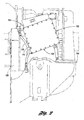
- Figure 2 is a side view of a crankcase ventilation system of a diesel engine including a multi-orifice crankcase air evacuator assembly according to the present invention.
- Figure 3 is a partly sectional side view of the multi-orifice crankcase air evacuator assembly of Figure 2.
- Figure 4 is a perspective view of the multi-orifice crankcase air evacuator assembly according to the present invention.
- Figure 5 is a sectional side view of the multi-orifice crankcase air evacuator assembly according to the present invention.
- Figure 6A is a perspective view of a nozzle head of the multi-orifice crankcase air evacuator assembly according to the present invention.
- Figure 6B is a side view of the nozzle head of Figure 6A.
- Figure 6C is a flange end view of the nozzle head of Figure 6A.
- Figure 7A is a partly sectional side view of the evacuator tube according to the present invention.
- Figure 7B is a partly sectional view seen along line 7B-7B of Figure 7A.
- Figures 2 through 7B depict an example of a multi-orifice crankcase air evacuator assembly 100 according to the present invention, shown in conjunction with an oil separator 102 of a diesel engine 104. While the diesel engine 104, by way of exemplification, is used to power a locomotive, other similar applications may include, for example, power generation and marine applications.
- a housing 106 provides a conduit for crankcase air from the crankcase 108 of the diesel engine 104, as for example a crankcase port 110 located at a top portion of the oil pan 112, to an exhaust port 114 which is in communication with the exhaust system of the engine.
- the housing 106 is a sheet metal fabrication.
- a lower part 106L of the housing 106 is interfaced with the oil separator 102 upstream of the multi-orifice crankcase air evacuator assembly 100, wherein the multi-orifice crankcase air evacuator assembly is operably interfaced with the housing 106 at an upper part 106U thereof so as to be in communication, at one end thereof, with the oil separator 102 and, at the other end thereof via suitable connection 128, with the exhaust port 114.
- a high pressure air line 116 is connected to a conventionally derived source of compressed air and to the multi-orifice crankcase air evacuator assembly 100.
- the multi-orifice crankcase air evacuator assembly 100 includes a multi-orifice nozzle 130 proximally positioned relative to an inlet 134 of an evacuator tube 132 such that high pressure nozzle air exiting the multi-orifice nozzle 130 passes into the evacuator tube 132, creating a low pressure region therearound which sucks ambient air in the upper part 106U of the housing 106 into the evacuator tube.
- crankcase air from the crankcase port 110 is drawn into the lower part 106L of the housing 106, through the housing passage 106P and into the upper part 106U of the housing so as to be thereupon sucked into the evacuator tube 132.
- the evacuator tube 132 is, at an outlet 136 thereof, connected to an exhaust port 114 of the engine 104, the crankcase air is expelled to the engine exhaust system.
- the multi-orifice nozzle 130 includes a nozzle body 140 connected, via the air line 116, to an external source of compressed air.
- the compressed air enters a nozzle chamber 142 of the nozzle body 140.
- the multi-orifice nozzle 130 further includes a nozzle head 144 connected with the nozzle body 140.
- the nozzle head 144 has a plurality of nozzle orifices 146a, 146b, 146c, 146d, 146e (preferably five in number), wherein each nozzle orifice communicates with the nozzle chamber 142.
- the nozzle orifices 146a-146e are mutually spaced in a symmetric arrangement so as to collectively provide a generally circumferential area of air movement as the high pressure nozzle air effuses from the nozzle orifices. It is notable that multiple nozzle orifices provide better gas mixing and movement than can be provided by a single nozzle orifice, resulting in better momentum exchange, and reduction of external air capacity to achieve a similar amount of crankcase air pumping.
- the multi-orifice nozzle 130 is constructed of a machined aluminum casting.
- the nozzle head 144 has a nozzle head flange 148 for connecting to the nozzle body 140, and is drilled therethrough to provide an air passageway 150 at each nozzle orifice 146a-146d.
- the symmetric arrangement is preferred to be an "X" pattern, wherein a nozzle orifice is located at the center C and each terminous T of each leg of the "X" pattern (see Figure 6C).
- an "X" pattern has a separation between the central nozzle orifice 146c and the distal nozzle orifices 146a, 146b, 146d, 146e along each leg of the "X" of about 0.544 inch, the diameter of each air passageway is about 0.25 inches, and the nozzle head has a length (including the nozzle head flange 148) of about 2.38 inches.
- the evacuation tube 132 is characterized by a tube body 160 defining a central passage 162 and a bell-mouth 164 integral with the tube body which is concentrically disposed at the inlet 134 thereof.
- the bell-mouth 164 smoothly merges with the central passage 162 so as to define thereat a throat 166.
- the bell-mouth 164 has a generally mushroom shape characterized by an annularly distributed convex air guide surface 168.
- the central passage 162 has a near portion 162n which serves as an air mixer 180 and a distal portion 162d that widens with increasing distance from the bell-mouth 164 and which serves as an air diffuser 182.
- the tube body 160 has a mounting flange 170 at the outlet 136 for interfitting with the connection 128 to the exhaust port 114 of the engine 104.
- a cross-bar bracket 172 is connected externally to the tube body 160 for providing a connection of the evacuator tube 102 to the housing 106.
- the air guide surface 168 of the bell-mouth 164 allows crankcase air to be sucked into the throat 166 over a 360 degree circumference in response to the high pressure nozzle air rapidly effusing from the nozzle orifices 146a-146e. Accordingly, a free and voluminous movement of the crankcase air into the throat is achieved.
- the near portion 162n of the central passage 162 provides an air mixing section whereat the nozzle air exchanges momentum with the crankcase air.
- the distal portion of the central passage serves as a diffuser which serves to recover kinetic energy in the mixed air flow stream.
- the evacuator tube 102 is composed of a machined aluminum casting.
- the length of the evacuator tube 102 may be about 14.67 inches
- the bell-mouth 164 may have an outer diameter of about 5.6 inches
- the near portion 162n of the central passage 162 may have a diameter of about 1.7 inches and a length of about 8 inches
- the distal portion 162d of the central passage may have a diameter at the outlet 136 of about 2.48 inches.
- the nozzle orifices 146a-146e are located in alignment with the central passage 162, in a close spaced proximity to the bell-mouth of, for example, about 0.5 inch (see D in Figure 5).
- crankcase air evacuator assembly Operation of the multi-orifice crankcase air evacuator assembly, will now be described with particular attention being directed to Figure 3.
- the crankcase air mixes with the nozzle air streams in the near portion 162a of the central passage, causing a momentum mixing therebetween, whereupon crankcase air rapidly moves with the nozzle air streams down the central passage.
- the distal portion 162b of the central passage allows expansion and velocity reduction of the mixed air, whereupon the mixed air has generally achieved atmospheric pressure by the time it reaches the outlet of the evacuator tube.
- the mixed air is then expelled to the exhaust outlet 114.
Landscapes
- Engineering & Computer Science (AREA)
- Mechanical Engineering (AREA)
- General Engineering & Computer Science (AREA)
- Jet Pumps And Other Pumps (AREA)
Abstract
Description
- This application is a continuation-in-part of US Serial No. 10/146,618 filed May 15, 2002.
- The present invention relates to crankcase ventilation of diesel internal combustion engines, particularly diesel engines used for locomotive applications.
- Diesel-powered locomotives generally require an absence of positive crankcase pressure. Yet, during the operation of internal combustion engines, blow-by gas from the combustion chamber during the combustion stroke causes a positive pressure in the crankcase which must be relieved. In the case of locomotive applications, it is desired that the crankcase generally be negatively pressured. Accordingly, since a simple valve or opening in the crankcase is inadequate, a crankcase ventilation system is utilized.
- The crankcase ventilation system on a locomotive diesel engine evacuates the excessive crankcase air in the crankcase (from seals and piston blow-by) to the exhaust stream and eventually the atmosphere. Included in the crankcase air is an oil mist that has two negative consequences. First, the oil mist contributes to the engine's emissions; and second, the oil leaves a coke deposit of carbon that can ignite and start railside fires.
- Figure 1 exemplifies a conventional diesel engine
crankcase ventilation system 10, including anoil separator 12 and anevacuator 14. Apipe connection 16 communicates generally horizontally with the crankcase, as for example at an upper portion of theoil pan 18. Anelbow 20 connects thepipe connection 16 to theoil separator 12, which has an off-setopening 22. Connected to the off-setopening 22 is theevacuator 14. Theevacuator 14 has avertical portion 24 and ahorizontal portion 26 demarcated by abend 28. The end of thehorizontal portion 26 is interfaced with anexhaust port 30 which communicates with the engine exhaust system. Thebend 28 is fitted with anozzle assembly 32. Thenozzle assembly 32 includes asingle orifice nozzle 34 internal to thehorizontal portion 26 which is directed down the horizontal portion toward theexhaust port 26, the horizontal portion diameter outwardly tapering with increasing distance from the nozzle assembly. Thenozzle assembly 32 is interfaced with a source of pressurized air external to the crankcase, via anair line 36. - In operation, pressurized air emanating from the nozzle blows air toward the exhaust port, causing a low pressure condition in the vertical portion of the evacuator. This low pressure zone communicates with the crankcase through the oil separator to cause crankcase air to be affirmatively evacuated from the crankcase. Oil-laden crankcase air passes through the oil separator, during which the expanded volume and vertical path combine to cause oil to precipitate out of the crankcase air and then flow back into the crankcase.
- Several drawbacks of the conventional diesel engine crankcase ventilation system are yet in need of redress, among those being a need to improve the efficiency and effectiveness of crankcase air removal into the exhaust port.
- The present invention is a multi-orifice crankcase air evacuator assembly for a diesel engine which provides improved efficiency and effectiveness of crankcase air removal into the exhaust port of the engine.
- The multi-orifice crankcase air evacuator assembly includes a multi-orifice nozzle interfaced with an evacuator tube. The multi-orifice crankcase air evacuator assembly is located in a housing which communicates with a crankcase port of the engine so that crankcase air is freely movable into the housing at the multi-orifice crankcase air evacuator assembly. The multi-orifice crankcase air evacuator assembly, in turn, is connected to an exhaust port of the engine which communicates to the engine exhaust system.
- The multi-orifice nozzle has a nozzle body connected to an external source of compressed air. The compressed air enters a nozzle chamber of the nozzle body. Connected with the nozzle body is a nozzle head having a number of nozzle orifices, preferably five, each communicating with the nozzle chamber. The nozzle orifices are mutually spaced in a symmetric arrangement (i.e., an "X" pattern) so as to collectively provide a generally circumferential area of air movement as the high pressure nozzle air rapidly effuses from the nozzle orifices.
- The evacuation tube has a tube body defining a central passage and a bell-mouth concentrically disposed at its inlet, whereat the bell-mouth merges with the central passage to define thereat a throat. The bell-mouth has a generally mushroom shape characterized by an annularly distributed convex air guide surface. The central passage has a near portion adjacent the throat which serves as an air mixer and a distal portion that widens with increasing distance from the bell-mouth and which serves as an air diffuser. At the outlet, the tube body has a flange for interfitting with a connection to exhaust port of the engine.
- Operatively, the nozzle orifices are located in alignment with the central passage, in close spaced proximity to the bell-mouth. As high pressure nozzle air exits the nozzle orifices, the respective high velocity nozzle air streams converge at the throat and pass rapidly along the central passage. This nozzle air movement creates a region of low pressure surrounding the bell-mouth. Consequently, crankcase air surrounding the bell-mouth is sucked into the throat at a large rate, and preferably in a generally laminar flow over the bell-mouth. The crankcase air mixes with the nozzle air streams in the near portion of the central passage, causing a momentum mixing therebetween which causes crankcase air to rapidly move with the air streams down the central passage. As this mixed air moves down the central passage, the distal portion of the central passage allows expansion and velocity reduction of the mixed air, whereupon the mixed air has generally achieved atmospheric pressure by the time it reaches the outlet.
- The bell-mouth allows for crankcase air to be sucked into the throat over a 360 degree circumference, which contributes to a free and voluminous movement of the crankcase air into the throat. The near portion of the central passage provides an air mixing section where the nozzle air exchanges momentum with the crankcase air. The distal portion of the central passage serves as a diffuser which serves to recover kinetic energy in the mixed air flow stream. The multiple nozzle orifices provide better gas mixing and movement than can be provided by a single nozzle orifice, resulting in better momentum exchange, and reduction of external air capacity to achieve a similar amount of crankcase air pumping.
- Accordingly, it is an object of the present invention to provide more efficient evacuation of crankcase air in connection with a crankcase air ventilation system of a diesel engine.
- It is an additional object of the present invention to provide improved evacuation of crankcase air in connection with a ventilation system of a diesel engine, wherein a multi-orifice nozzle is coupled with an evacuator tube configured to provide efficient air entry, mixing and diffusion.
- These and additional objects, features and advantages of the present invention will become clearer from the following specification of a preferred embodiment.
- Figure 1 is a side view of a conventional crankcase ventilation system for a diesel engine.
- Figure 2 is a side view of a crankcase ventilation system of a diesel engine including a multi-orifice crankcase air evacuator assembly according to the present invention.
- Figure 3 is a partly sectional side view of the multi-orifice crankcase air evacuator assembly of Figure 2.
- Figure 4 is a perspective view of the multi-orifice crankcase air evacuator assembly according to the present invention.
- Figure 5 is a sectional side view of the multi-orifice crankcase air evacuator assembly according to the present invention.
- Figure 6A is a perspective view of a nozzle head of the multi-orifice crankcase air evacuator assembly according to the present invention.
- Figure 6B is a side view of the nozzle head of Figure 6A.
- Figure 6C is a flange end view of the nozzle head of Figure 6A.
- Figure 7A is a partly sectional side view of the evacuator tube according to the present invention.
- Figure 7B is a partly sectional view seen along
line 7B-7B of Figure 7A. - Referring now to the drawings, Figures 2 through 7B depict an example of a multi-orifice crankcase
air evacuator assembly 100 according to the present invention, shown in conjunction with anoil separator 102 of adiesel engine 104. While thediesel engine 104, by way of exemplification, is used to power a locomotive, other similar applications may include, for example, power generation and marine applications. - As can be understood from reference to Figures 2 and 3, a
housing 106 provides a conduit for crankcase air from thecrankcase 108 of thediesel engine 104, as for example acrankcase port 110 located at a top portion of theoil pan 112, to anexhaust port 114 which is in communication with the exhaust system of the engine. Thehousing 106 is a sheet metal fabrication. Alower part 106L of thehousing 106 is interfaced with theoil separator 102 upstream of the multi-orifice crankcaseair evacuator assembly 100, wherein the multi-orifice crankcase air evacuator assembly is operably interfaced with thehousing 106 at anupper part 106U thereof so as to be in communication, at one end thereof, with theoil separator 102 and, at the other end thereof viasuitable connection 128, with theexhaust port 114. A highpressure air line 116 is connected to a conventionally derived source of compressed air and to the multi-orifice crankcaseair evacuator assembly 100. - Referring now additionally to Figures 4 and 5, the multi-orifice crankcase
air evacuator assembly 100 includes amulti-orifice nozzle 130 proximally positioned relative to aninlet 134 of anevacuator tube 132 such that high pressure nozzle air exiting themulti-orifice nozzle 130 passes into theevacuator tube 132, creating a low pressure region therearound which sucks ambient air in theupper part 106U of thehousing 106 into the evacuator tube. Since the upper andlower parts housing 106 communicate with each other via ahousing passage 106P, because of establishment of the aforementioned the low pressure region, crankcase air from thecrankcase port 110 is drawn into thelower part 106L of thehousing 106, through thehousing passage 106P and into theupper part 106U of the housing so as to be thereupon sucked into theevacuator tube 132. And, since theevacuator tube 132 is, at anoutlet 136 thereof, connected to anexhaust port 114 of theengine 104, the crankcase air is expelled to the engine exhaust system. - As shown at Figures 4 through 6C, the
multi-orifice nozzle 130 includes anozzle body 140 connected, via theair line 116, to an external source of compressed air. The compressed air enters anozzle chamber 142 of thenozzle body 140. Themulti-orifice nozzle 130 further includes anozzle head 144 connected with thenozzle body 140. Thenozzle head 144 has a plurality ofnozzle orifices nozzle chamber 142. Thenozzle orifices 146a-146e are mutually spaced in a symmetric arrangement so as to collectively provide a generally circumferential area of air movement as the high pressure nozzle air effuses from the nozzle orifices. It is notable that multiple nozzle orifices provide better gas mixing and movement than can be provided by a single nozzle orifice, resulting in better momentum exchange, and reduction of external air capacity to achieve a similar amount of crankcase air pumping. - By way of preferred example, the
multi-orifice nozzle 130 is constructed of a machined aluminum casting. Thenozzle head 144 has anozzle head flange 148 for connecting to thenozzle body 140, and is drilled therethrough to provide anair passageway 150 at eachnozzle orifice 146a-146d. The symmetric arrangement is preferred to be an "X" pattern, wherein a nozzle orifice is located at the center C and each terminous T of each leg of the "X" pattern (see Figure 6C). For example, an "X" pattern has a separation between thecentral nozzle orifice 146c and thedistal nozzle orifices - Referring now additionally to Figures 7A and 7B, the
evacuation tube 132 is characterized by atube body 160 defining acentral passage 162 and a bell-mouth 164 integral with the tube body which is concentrically disposed at theinlet 134 thereof. The bell-mouth 164 smoothly merges with thecentral passage 162 so as to define thereat athroat 166. The bell-mouth 164 has a generally mushroom shape characterized by an annularly distributed convexair guide surface 168. Thecentral passage 162 has anear portion 162n which serves as anair mixer 180 and adistal portion 162d that widens with increasing distance from the bell-mouth 164 and which serves as anair diffuser 182. Thetube body 160 has a mountingflange 170 at theoutlet 136 for interfitting with theconnection 128 to theexhaust port 114 of theengine 104. Generally, medial of thenear portion 162n, across-bar bracket 172 is connected externally to thetube body 160 for providing a connection of theevacuator tube 102 to thehousing 106. - The
air guide surface 168 of the bell-mouth 164 allows crankcase air to be sucked into thethroat 166 over a 360 degree circumference in response to the high pressure nozzle air rapidly effusing from thenozzle orifices 146a-146e. Accordingly, a free and voluminous movement of the crankcase air into the throat is achieved. Thenear portion 162n of thecentral passage 162 provides an air mixing section whereat the nozzle air exchanges momentum with the crankcase air. The distal portion of the central passage serves as a diffuser which serves to recover kinetic energy in the mixed air flow stream. - By way of preferred example, the
evacuator tube 102 is composed of a machined aluminum casting. For example, the length of theevacuator tube 102 may be about 14.67 inches, the bell-mouth 164 may have an outer diameter of about 5.6 inches, thenear portion 162n of thecentral passage 162 may have a diameter of about 1.7 inches and a length of about 8 inches, and thedistal portion 162d of the central passage may have a diameter at theoutlet 136 of about 2.48 inches. By way of further exemplification, thenozzle orifices 146a-146e are located in alignment with thecentral passage 162, in a close spaced proximity to the bell-mouth of, for example, about 0.5 inch (see D in Figure 5). - Operation of the multi-orifice crankcase air evacuator assembly, will now be described with particular attention being directed to Figure 3. As high pressure nozzle air AN rapidly and forcefully exits the nozzle orifices, the respective high velocity air streams converge at the throat and pass rapidly along the central passage. This air movement creates a region R of low pressure surrounding the bell-mouth. Consequently, ambient air of the housing is sucked into the throat at a large rate, thereby causing a pumping movement of the crankcase air AC out from the crankcase and suckingly into the throat. The crankcase air mixes with the nozzle air streams in the near portion 162a of the central passage, causing a momentum mixing therebetween, whereupon crankcase air rapidly moves with the nozzle air streams down the central passage. As this mixed air AM moves down the central passage, the distal portion 162b of the central passage allows expansion and velocity reduction of the mixed air, whereupon the mixed air has generally achieved atmospheric pressure by the time it reaches the outlet of the evacuator tube. The mixed air is then expelled to the
exhaust outlet 114. - To those skilled in the art to which this invention appertains, the above described preferred embodiment may be subject to change or modification. Such change or modification can be carried out without departing from the scope of the invention, which is intended to be limited only by the scope of the appended claims.
Claims (16)
- A multi-orifice crankcase air evacuator assembly for a crankcase ventilation system comprising:wherein when air pressurably effuses from said plurality of nozzle orifices, the air passes into said inlet, thereby causing a low pressure region therearound which sucks ambient air into said inlet.a multi-orifice nozzle comprising a plurality of nozzle orifices; andan evacuator tube comprising a tube body having a central passage, said central passage having an inlet and an opposite outlet; said plurality of nozzle orifices being located proximal to, and in alignment with, said inlet of said central passage;
- The multi-orifice crankcase air evacuator assembly of Claim 1, wherein said evacuator tube further comprises a bell-mouth integrally formed of said tube body at said inlet in concentric disposition relative to said central passage, said bell-mouth having an annularly distributed convex air guide surface which smoothly merges with said central passage at said inlet to thereby form a throat.
- The multi-orifice crankcase air evacuator assembly of Claim 2, wherein said central passage comprises a near portion and a distal portion, said near portion extending between said throat and said distal portion, said distal portion extending between said near portion and said outlet, said near portion having a substantially constant diameter serving as an air mixer, said distal portion having an increasing diameter with increasing distance from said near portion serving as an air diffuser.
- The multi-orifice crankcase air evacuator assembly of Claim 1, wherein said multi-orifice nozzle further comprises:wherein said plurality of nozzle orifices are formed integrally of said nozzle head, and wherein each nozzle orifice of said plurality of nozzle orifices comprises an air passageway communicating with said nozzle chamber.a nozzle body having a nozzle chamber formed therewithin; anda nozzle head connected to said nozzle body;
- The multi-orifice crankcase air evacuator assembly of Claim 4, wherein said evacuator tube further comprises a bell-mouth integrally formed of said tube body at said inlet in concentric disposition relative to said central passage, said bell-mouth having an annularly distributed convex air guide surface which smoothly merges with said central passage at said inlet to thereby form a throat.
- The multi-orifice crankcase air evacuator assembly of Claim 5, wherein said central passage comprises a near portion and a distal portion, said near portion extending between said throat and said distal portion, said distal portion extending between said near portion and said outlet, said near portion having a substantially constant diameter serving as an air mixer, said distal portion having an increasing diameter with increasing distance from said near portion serving as an air diffuser.
- The multi-orifice crankcase air evacuator assembly of Claim 6, wherein said plurality of nozzle orifices comprises five nozzle orifices arranged in an "X" pattern.
- A crankcase ventilation system interfaced between a crankcase port and an exhaust port of a diesel engine, comprising:wherein said nozzle air passes into said inlet thereby creating a low pressure region therearound which sucks ambient air of said housing into said inlet and thereby evacutes said crankcase air from said crankcase port and expels the crankcase air to said exhaust port.a housing connected between the crankcase and exhaust ports of the diesel engine;a source of compressed air; anda crankcase air evacuator assembly comprising:a multi-orifice nozzle comprising a plurality of nozzle orifices located within said housing, said multi-orifice nozzle being connected to said source of compressed air, wherein air from said source pressurably effuses as nozzle air from said plurality of nozzle orifices; andan evacuator tube located in said housing, said evacuator tube comprising a tube body having a central passage, said central passage having an inlet and an opposite outlet interconnected with said exhaust port; said plurality of nozzle orifices being located proximal to, and in alignment with, said inlet of said central passage;
- The crankcase ventilation system of Claim 8, wherein said evacuator tube further comprises a bell-mouth integrally formed of said tube body at said inlet in concentric disposition relative to said central passage, said bell-mouth having an annularly distributed convex air guide surface which smoothly merges with said central passage at said inlet to thereby form a throat.
- The crankcase ventilation system of Claim 9, wherein said central passage comprises a near portion and a distal portion, said near portion extending between said throat and said distal portion, said distal portion extending between said near portion and said outlet, said near portion having a substantially constant diameter serving as an air mixer, said distal portion having an increasing diameter with increasing distance from said near portion serving as an air diffuser.
- The crankcase ventilation system of Claim 8, wherein said multi-orifice nozzle further comprises:wherein said plurality of nozzle orifices are formed integrally of said nozzle head, and wherein each nozzle orifice of said plurality of nozzle orifices comprises an air passageway communicating with said nozzle chamber.a nozzle body connected with said source, said nozzle body having a nozzle chamber formed therewithin, said nozzle chamber communicating with the air from said source; anda nozzle head connected to said nozzle body;
- The crankcase ventilation system of Claim 11, wherein said evacuator tube further comprises a bell-mouth integrally formed of said tube body at said inlet in concentric disposition relative to said central passage, said bell-mouth having an annularly distributed convex air guide surface which smoothly merges with said central passage at said inlet to thereby form a throat.
- The crankcase ventilation system of Claim 12, wherein said central passage comprises a near portion and a distal portion, said near portion extending between said throat and said distal portion, said distal portion extending between said near portion and said outlet, said near portion having a substantially constant diameter serving as an air mixer, said distal portion having an increasing diameter with increasing distance from said near portion serving as an air diffuser.
- The crankcase ventilation system of Claim 13, wherein said plurality of nozzle orifices comprises five nozzle orifices arranged in an "X" pattern.
- An evacuator tube for an evacuator of a crankcase ventilation system, comprising:a tube body having a central passage, said central passage having an inlet and an opposite outlet; anda bell-mouth integrally formed of said tube body at said inlet in concentric disposition relative to said central passage, said bell-mouth having an annularly distributed convex air guide surface which smoothly merges with said central passage at said inlet to thereby form a throat.
- The evacuator tube of Claim 15, wherein said central passage comprises a near portion and a distal portion, said near portion extending between said throat and said distal portion, said distal portion extending between said near portion and said outlet, said near portion having a substantially constant diameter serving as an air mixer, said distal portion having an increasing diameter with increasing distance from said near portion serving as an air diffuser.
Applications Claiming Priority (4)
| Application Number | Priority Date | Filing Date | Title |
|---|---|---|---|
| US14661802A | 2002-05-15 | 2002-05-15 | |
| US146618 | 2002-05-15 | ||
| US243272 | 2002-09-13 | ||
| US10/243,272 US6694957B2 (en) | 2002-05-15 | 2002-09-13 | Multi-orifice nozzle air evacuator assembly for a ventilation system of a diesel engine |
Publications (2)
| Publication Number | Publication Date |
|---|---|
| EP1367232A1 true EP1367232A1 (en) | 2003-12-03 |
| EP1367232B1 EP1367232B1 (en) | 2008-02-20 |
Family
ID=29423065
Family Applications (1)
| Application Number | Title | Priority Date | Filing Date |
|---|---|---|---|
| EP03008105A Expired - Lifetime EP1367232B1 (en) | 2002-05-15 | 2003-04-07 | Multi-orifice nozzle air evacuator assembly for a crankcase breather system of a diesel engine |
Country Status (1)
| Country | Link |
|---|---|
| EP (1) | EP1367232B1 (en) |
Cited By (2)
| Publication number | Priority date | Publication date | Assignee | Title |
|---|---|---|---|---|
| DE202006001287U1 (en) * | 2006-01-27 | 2007-06-06 | Mann+Hummel Gmbh | Pressure control valve |
| DE202008005363U1 (en) * | 2008-04-17 | 2009-09-03 | Mann+Hummel Gmbh | Crankcase breather of an internal combustion engine |
Citations (4)
| Publication number | Priority date | Publication date | Assignee | Title |
|---|---|---|---|---|
| US16456A (en) * | 1857-01-20 | Improved machine for bending sheet metal | ||
| US3050376A (en) * | 1958-02-06 | 1962-08-21 | Gen Motors Corp | Apparatus for disposal of carburetor and crankcase fumes |
| US4197703A (en) * | 1978-04-24 | 1980-04-15 | J. I. Case Company | Exhaust system for straddle carrier engines |
| US4557226A (en) * | 1983-11-14 | 1985-12-10 | Bbc Brown, Boveri & Company, Limited | Device for returning the blow-by rate from the crankcase into the system of a supercharged internal combustion engine |
-
2003
- 2003-04-07 EP EP03008105A patent/EP1367232B1/en not_active Expired - Lifetime
Patent Citations (4)
| Publication number | Priority date | Publication date | Assignee | Title |
|---|---|---|---|---|
| US16456A (en) * | 1857-01-20 | Improved machine for bending sheet metal | ||
| US3050376A (en) * | 1958-02-06 | 1962-08-21 | Gen Motors Corp | Apparatus for disposal of carburetor and crankcase fumes |
| US4197703A (en) * | 1978-04-24 | 1980-04-15 | J. I. Case Company | Exhaust system for straddle carrier engines |
| US4557226A (en) * | 1983-11-14 | 1985-12-10 | Bbc Brown, Boveri & Company, Limited | Device for returning the blow-by rate from the crankcase into the system of a supercharged internal combustion engine |
Non-Patent Citations (1)
| Title |
|---|
| PATENT ABSTRACTS OF JAPAN vol. 013, no. 202 (M - 824) 12 May 1989 (1989-05-12) * |
Cited By (2)
| Publication number | Priority date | Publication date | Assignee | Title |
|---|---|---|---|---|
| DE202006001287U1 (en) * | 2006-01-27 | 2007-06-06 | Mann+Hummel Gmbh | Pressure control valve |
| DE202008005363U1 (en) * | 2008-04-17 | 2009-09-03 | Mann+Hummel Gmbh | Crankcase breather of an internal combustion engine |
Also Published As
| Publication number | Publication date |
|---|---|
| EP1367232B1 (en) | 2008-02-20 |
Similar Documents
| Publication | Publication Date | Title |
|---|---|---|
| US6694957B2 (en) | Multi-orifice nozzle air evacuator assembly for a ventilation system of a diesel engine | |
| CN105073219B (en) | Gas oil separator with jet enhanced impingement and related method | |
| JP6480589B2 (en) | Crankcase ventilation aspirator | |
| US20080173284A1 (en) | Engine pcv system with venturi nozzle for flow regulation | |
| US20140033922A1 (en) | Methods and Assemblies for Separating Liquid from a Gas-Liquid Stream | |
| US11512617B2 (en) | Jet pump diffuser for a separator | |
| CN100549402C (en) | Quartastroke engine with noise release of reduction | |
| JP2018040252A (en) | Blow-by gas processing device for a supercharged internal combustion engine | |
| ITRM990529A1 (en) | AIR AND FUEL DELIVERY SYSTEM FOR INJECTION INTERNAL COMBUSTION ENGINES. | |
| CN1088794C (en) | Exhaust manifold device | |
| EP1367232B1 (en) | Multi-orifice nozzle air evacuator assembly for a crankcase breather system of a diesel engine | |
| JPH0432209B2 (en) | ||
| US4947806A (en) | Engine breather oil recovery system | |
| JP2008180134A (en) | Engine | |
| FI114561B (en) | Turbocharger | |
| CN1840885B (en) | Two-stroke motor | |
| CN104033210B (en) | PCV system for two cylinder engines | |
| US8413639B2 (en) | Fuel supplying apparatus for internal combustion engine | |
| JP3109364B2 (en) | Intake device for internal combustion engine | |
| JP3142576B2 (en) | Dynamic gas seal for internal combustion engines | |
| WO2012012329A1 (en) | Heavy particle oil separator splash shield | |
| CA1255171A (en) | Air silencer for an internal combustion engine | |
| JPH0587211U (en) | Blow-by gas treatment device for internal combustion engine | |
| JPH09236013A (en) | Variable flow ejector, ejector device, and dust ejector device | |
| US11459918B2 (en) | Engine assembly |
Legal Events
| Date | Code | Title | Description |
|---|---|---|---|
| PUAI | Public reference made under article 153(3) epc to a published international application that has entered the european phase |
Free format text: ORIGINAL CODE: 0009012 |
|
| AK | Designated contracting states |
Kind code of ref document: A1 Designated state(s): AT BE BG CH CY CZ DE DK EE ES FI FR GB GR HU IE IT LI LU MC NL PT RO SE SI SK TR |
|
| AX | Request for extension of the european patent |
Extension state: AL LT LV MK |
|
| 17P | Request for examination filed |
Effective date: 20040308 |
|
| 17Q | First examination report despatched |
Effective date: 20040506 |
|
| AKX | Designation fees paid |
Designated state(s): DE FR GB |
|
| RAP1 | Party data changed (applicant data changed or rights of an application transferred) |
Owner name: ELECTRO-MOTIVE DIESEL, INC. |
|
| 17Q | First examination report despatched |
Effective date: 20040506 |
|
| GRAP | Despatch of communication of intention to grant a patent |
Free format text: ORIGINAL CODE: EPIDOSNIGR1 |
|
| GRAS | Grant fee paid |
Free format text: ORIGINAL CODE: EPIDOSNIGR3 |
|
| GRAA | (expected) grant |
Free format text: ORIGINAL CODE: 0009210 |
|
| AK | Designated contracting states |
Kind code of ref document: B1 Designated state(s): DE FR GB |
|
| REG | Reference to a national code |
Ref country code: GB Ref legal event code: FG4D |
|
| REF | Corresponds to: |
Ref document number: 60319180 Country of ref document: DE Date of ref document: 20080403 Kind code of ref document: P |
|
| ET | Fr: translation filed | ||
| PLBE | No opposition filed within time limit |
Free format text: ORIGINAL CODE: 0009261 |
|
| STAA | Information on the status of an ep patent application or granted ep patent |
Free format text: STATUS: NO OPPOSITION FILED WITHIN TIME LIMIT |
|
| 26N | No opposition filed |
Effective date: 20081121 |
|
| REG | Reference to a national code |
Ref country code: DE Ref legal event code: R082 Ref document number: 60319180 Country of ref document: DE Representative=s name: WAGNER & GEYER PARTNERSCHAFT PATENT- UND RECHT, DE Ref country code: DE Ref legal event code: R082 Ref document number: 60319180 Country of ref document: DE Representative=s name: WAGNER & GEYER PARTNERSCHAFT MBB PATENT- UND R, DE |
|
| PGFP | Annual fee paid to national office [announced via postgrant information from national office to epo] |
Ref country code: DE Payment date: 20120430 Year of fee payment: 10 |
|
| PGFP | Annual fee paid to national office [announced via postgrant information from national office to epo] |
Ref country code: FR Payment date: 20130417 Year of fee payment: 11 |
|
| PG25 | Lapsed in a contracting state [announced via postgrant information from national office to epo] |
Ref country code: DE Free format text: LAPSE BECAUSE OF NON-PAYMENT OF DUE FEES Effective date: 20131101 |
|
| REG | Reference to a national code |
Ref country code: DE Ref legal event code: R119 Ref document number: 60319180 Country of ref document: DE Effective date: 20131101 |
|
| REG | Reference to a national code |
Ref country code: FR Ref legal event code: ST Effective date: 20141231 |
|
| PG25 | Lapsed in a contracting state [announced via postgrant information from national office to epo] |
Ref country code: FR Free format text: LAPSE BECAUSE OF NON-PAYMENT OF DUE FEES Effective date: 20140430 |
|
| PGFP | Annual fee paid to national office [announced via postgrant information from national office to epo] |
Ref country code: GB Payment date: 20150325 Year of fee payment: 13 |
|
| GBPC | Gb: european patent ceased through non-payment of renewal fee |
Effective date: 20160407 |
|
| PG25 | Lapsed in a contracting state [announced via postgrant information from national office to epo] |
Ref country code: GB Free format text: LAPSE BECAUSE OF NON-PAYMENT OF DUE FEES Effective date: 20160407 |