EP1367224B1 - Methods and apparatus for cooling gas turbine engine nozzle assemblies - Google Patents
Methods and apparatus for cooling gas turbine engine nozzle assemblies Download PDFInfo
- Publication number
- EP1367224B1 EP1367224B1 EP03251919A EP03251919A EP1367224B1 EP 1367224 B1 EP1367224 B1 EP 1367224B1 EP 03251919 A EP03251919 A EP 03251919A EP 03251919 A EP03251919 A EP 03251919A EP 1367224 B1 EP1367224 B1 EP 1367224B1
- Authority
- EP
- European Patent Office
- Prior art keywords
- cooling
- airfoil
- cooling circuit
- trailing edge
- nozzle
- Prior art date
- Legal status (The legal status is an assumption and is not a legal conclusion. Google has not performed a legal analysis and makes no representation as to the accuracy of the status listed.)
- Expired - Fee Related
Links
Images


Classifications
-
- F—MECHANICAL ENGINEERING; LIGHTING; HEATING; WEAPONS; BLASTING
- F01—MACHINES OR ENGINES IN GENERAL; ENGINE PLANTS IN GENERAL; STEAM ENGINES
- F01D—NON-POSITIVE DISPLACEMENT MACHINES OR ENGINES, e.g. STEAM TURBINES
- F01D5/00—Blades; Blade-carrying members; Heating, heat-insulating, cooling or antivibration means on the blades or the members
- F01D5/12—Blades
- F01D5/14—Form or construction
- F01D5/18—Hollow blades, i.e. blades with cooling or heating channels or cavities; Heating, heat-insulating or cooling means on blades
- F01D5/187—Convection cooling
-
- Y—GENERAL TAGGING OF NEW TECHNOLOGICAL DEVELOPMENTS; GENERAL TAGGING OF CROSS-SECTIONAL TECHNOLOGIES SPANNING OVER SEVERAL SECTIONS OF THE IPC; TECHNICAL SUBJECTS COVERED BY FORMER USPC CROSS-REFERENCE ART COLLECTIONS [XRACs] AND DIGESTS
- Y02—TECHNOLOGIES OR APPLICATIONS FOR MITIGATION OR ADAPTATION AGAINST CLIMATE CHANGE
- Y02T—CLIMATE CHANGE MITIGATION TECHNOLOGIES RELATED TO TRANSPORTATION
- Y02T50/00—Aeronautics or air transport
- Y02T50/60—Efficient propulsion technologies, e.g. for aircraft
Definitions
- This invention relates generally to gas turbine engine cooling circuits and more particularly, to methods and apparatus for cooling gas turbine engine nozzle assemblies.
- Gas turbine engines include combustors, which ignite fuel-air mixtures, which are then channeled through a turbine nozzle assembly toward a turbine.
- At least some known turbine nozzle assemblies include a plurality of nozzles arranged circumferentially within the engine downstream from the combustors.
- Each nozzle includes a hollow airfoil vane that extends between integrally-formed inner and outer band platforms. The nozzles are cooled by a combination of internal convective cooling and gas side film cooling.
- Each hollow airfoil is supplied cooling air through an internally-defined cavity that is bounded by a pair of connected sidewalls. Cooling of engine components, such as components of the high pressure turbine, is necessary due to thermal stress limitations of materials used in construction of such components. Typically, cooling air is extracted air from an outlet of the compressor and the cooling air is used to cool, for example, turbine nozzles. At least some known turbine nozzles include cooling circuits within the cavity which define flow paths for channeling cooling air flow through the cavity for cooling the airfoil prior to the air flow being discharged downstream through trailing edge slots defined within the airfoil.
- a serpentine shaped path or channel having multiple chamber passes is defined.
- the heat transfer coefficient of coolant flowing through a channel is a function of the local flow velocity in the circuit. Because the metal temperature distribution of a typical vane airfoil is such that the trailing edge is significantly hotter than a temperature of the bulk of the airfoil, at least some known airfoils use turbulence promoters such as pins, turbulators, and other roughening devices to increase the heat transfer coefficient of the coolant flowing through the channel. However, within channel flow circuits, as a portion of the airflow is channeled aftward through the trailing edge slots see e.g.
- a region of low heat transfer coefficient may form near the end of the cooling path.
- at least some known airfoils use local film cooling.
- a region of low cooling at the end of a cooling circuit may not be solved by local film cooling, and as a result, may limit the operating range and acceptable applications of the engine.
- a method for fabricating a nozzle for a gas turbine engine includes an airfoil, and the method includes forming the airfoil to include a suction side and a pressure side connected at a leading edge and a trailing edge such that a cooling cavity and a cooling circuit are defined within the airfoil, wherein the suction side and the pressure side extend radially between a tip and a root.
- the method also includes forming a plurality of cooling slots within the airfoil that extend from the cooling circuit towards the airfoil trailing edge, and forming a control vane within the cooling circuit to facilitate maintaining a substantially constant cooling effectiveness within the cooling circuit.
- a turbine nozzle for a gas turbine engine in another aspect, includes an airfoil vane that includes a first wall, a second wall, a plurality of trailing edge cooling slots, and a cooling circuit that extends between the first and second walls.
- the cooling circuit is upstream from the trailing edge cooling slots for channeling cooling air to the trailing edge cooling slots.
- the cooling circuit includes at least one control vane extending between the first and second walls. The control vane is arcuate and extends upstream from the trailing edge cooling slots for maintaining a substantially constant cooling effectiveness within said cooling circuit.
- an airfoil for a gas turbine engine nozzle includes a root, a tip, a cooling circuit, a plurality of trailing edge cooling slots, and a convex sidewall and a concave sidewall that are connected at a trailing edge.
- the plurality of trailing edge cooling slots extend from the cooling circuit towards the airfoil trailing edge.
- Each sidewall extends between the root and tip.
- the cooling circuit is defined between the sidewalls and includes a plurality of pins and a control vane.
- the plurality of pins and the control vane extend between the sidewalls and define a flowpath for channeling cooling air through the cooling circuit into the trailing edge cooling slots.
- the control vane is configured to facilitate maintaining a substantially constant cooling effectiveness within the cooling circuit.
- Figure 1 is a schematic illustration of a gas turbine engine 10 including a fan assembly 12, a high-pressure compressor 14, and a combustor 16.
- Engine 10 also includes a high-pressure turbine 18 and a low-pressure turbine 20.
- Engine 10 has an intake, or upstream, side 28 and an exhaust, or downstream, side 30.
- engine 10 is a CF6-80 engine commercially available from General Electric Aircraft Engines, Cincinnati, Ohio.
- Airflow from combustor 16 is discharged through a turbine nozzle assembly (not shown in Figure 1) that includes a plurality of nozzles (not shown in Figure 1) and used to drive turbines 18 and 20.
- Turbine 20 in turn, drives fan assembly 12, and turbine 18 drives high-pressure compressor 14.
- FIG 2 is a perspective view of turbine nozzle assembly 50 that may be used with a gas turbine engine, such as engine 10 (shown in Figure 1).
- Nozzle assembly 50 includes a plurality of nozzles 51 which extend circumferentially within engine 10.
- Each nozzle 51 includes an airfoil vane 52 that extends between a radially outer band or platform 54 and a radially inner band or platform 56. More specifically, in the exemplary embodiment, each band 54 and 56 is formed integrally with each airfoil vane 52.
- Each airfoil vane 52 includes a first sidewall 60 and a second sidewall 62.
- First sidewall 60 is convex and defines a suction side of airfoil vane 52
- second sidewall 62 is concave and defines a pressure side of airfoil vane 52.
- Sidewalls 60 and 62 are joined at a leading edge 64 and at an axially-spaced trailing edge 66 of airfoil vane 52.
- First and second sidewalls 60 and 62 extend longitudinally, or radially outwardly, in span from radially inner band 56 to radially outer band 54.
- An airfoil vane root 70 is defined as being adjacent inner band 56
- an airfoil vane tip 72 is defined as being adjacent outer band 54.
- first and second sidewalls 60 and 62 respectively, define a cooling cavity (not shown in Figure 2) within airfoil vane 52. More specifically, the cooling cavity is bounded by an inner surface (not shown) of each respective sidewall 60 and 62.
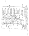
- FIG 3 is an enlarged schematic cross-sectional view of a cooling circuit 80 that may be used with turbine nozzle assembly 50.
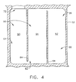
- Figure 4 is an exemplary schematic block diagram of a cooling cavity 82 including cooling circuit 80.
- Each vane cooling cavity 82 is defined by an inner surface (not shown) of each vane 52.
- Cooling cavity 82 includes a plurality of inner walls 84 which partition cooling cavity 82 into a plurality of cooling chambers 86.
- the geometry and interrelationship of chambers 86 to walls 84 varies with the intended use of vane 52. More specifically, in the exemplary embodiment, each vane 52 includes a forward cooling chamber 90, an aft cooling chamber 92, and at least one mid cooling chamber 94. Chambers 90, 92, and 94 are bounded by airfoil first and second sidewalls 60 and 62, respectively (shown in Figure 2).
- forward cooling chamber 90 extends longitudinally or radially through vane 52 to airfoil tip 72, and is bordered by airfoil first and second sidewalls 60 and 62, and by airfoil leading edge 64.
- Mid cooling chamber 94 is between forward cooling chamber 90 and aft cooling chamber 92.
- chambers 90, 92, and 94 are in flow communication and form a serpentine cooling passageway extending through vane 52, such that primary cooling fluid supplied from mid cooling chamber 94 enters aft cooling chamber 92 adjacent airfoil vane tip 72.
- Aft cooling chamber 92 extends longitudinally or radially through 52, and is bordered by airfoil first and second sidewalls 60 and 62, respectively, and by airfoil trailing edge 66.
- Cooling circuit 80 is defined within aft cooling chamber 92 and is upstream from an arrangement of trailing edge cooling slots 96, such that cooling fluid discharged from cooling circuit 80 exits vane 52 through trailing edge cooling slots 96. More specifically, primary cooling fluid is directed radially through chamber 92 into cooling circuit 80 prior to the fluid being channeled through trailing edge cooling slots 96.
- a flow path through cooling circuit 80 is defined by a pin bank 100 that includes a plurality of pins 102, and by a plurality of turbulators 106 included within cooling circuit 80.
- Pins 102 extend between sidewalls 60 and 62 to facilitate increasing cooling effectiveness within airfoil vane 52.
- Turbulators 106 extend partially between sidewalls 60 and 62, and are spaced radially, such that a tortuous flowpath is defined therebetween. Turbulators 106 guide a portion of the cooling fluid passing therethrough through trailing edge cooling slots 96 and channel the remaining cooling fluid radially through cooling circuit 80.
- Pins 102 and turbulators 106 induce turbidity into cooling fluid flowing therein to facilitate increasing cooling effectiveness of cooling circuit 80.
- Cooling circuit 80 also includes a control vane 110 which extends upstream from trailing edge slots 96. More specifically, control vane 110 is arcuate and extends from trailing edge slots 96 partially across chamber 92 towards airfoil vane root 70, such that a passageway 112 is defined between an end 114 of control vane 110 and root 70. Control vane 110 extends between sidewalls 60 and 62 to facilitate structurally enhancing nozzle 51, and thus facilitates reducing bulging stresses in airfoil vane 52 when used with advanced high pressure engines.
- a plurality of cooling film openings 120 are positioned immediately upstream from control vane 110 along a leading edge side 122 of control vane 110. Openings 120 receive cooling fluid from upstream control vane 110 and discharge the fluid downstream from control vane 110 between control vane 110 and trailing edge slots 96.
- Control circuit 80 also includes a pair of secondary cooling or resupply flow openings 126. More specifically, a first secondary opening 130 is positioned approximately midway through cooling circuit 80. Resupplied or secondary cooling fluid flow introduced through opening 130 is directed into circuit 80 towards trailing edge cooling slots 96. A second secondary cooling opening 134 is positioned adjacent airfoil vane 52 such that cooling fluid flow introduced through opening 134 is directed into circuit 80 towards trailing edge cooling slots 96 and through passageway 112. Additionally, because control vane 110 extends partially across chamber 92 towards mid cooling chamber 94, a cross-sectional area of the flow path within cooling circuit 80 is decreased, which facilitates maintaining a velocity of cooling fluid flowing through control vane 110.
- cooling fluid is supplied to each airfoil vane cooling cavity 82.
- nozzle cooling cavity 82 receives cooling air discharged from a compressor, such as compressor 14 (shown in Figure 1).
- the cooling fluid is channeled through chambers 90 and 94 into chamber 92 and cooling circuit 80.
- a portion of the cooling fluid is directed aftward by pins 102 and turbulators 106 through trailing edge cooling slots 96. More specifically, as pins 102 and turbulators 106 direct cooling fluid aftward, the remaining cooling fluid directed is directed radially through cooling circuit 80 at a reduced velocity and pressure.
- cooling circuit 80 To enhance the cooling effectiveness of circuit 80 and to facilitate minimizing the effects of the reduced fluid velocity and pressure, additional cooling fluid, known as secondary or resupply cooling fluid, is supplied to cooling circuit 80 through first secondary opening 130. Opening 130 facilitates replenishing the cooling fluid within cooling circuit 80 that had been directed through trailing edge cooling slots 96.
- the resupply cooling fluid is routed from chamber 94.
- control vane 110 Downstream from opening 130, control vane 110 facilitates maintaining cooling fluid flow velocity and pressure within circuit 80. More specifically, the arcuate shape of control vane 110 decreases the cross sectional area of the flow path between vane 110 and chamber 94, which facilitates maintaining a velocity of the coolant fluid flow between vane 110 and chamber 94. Additionally, the arcuate shape of control vane 110 facilitates shifting a low internal pressure region 140 of vane 52 aftward to a location immediately downstream from vane 110 and between vane 110 and slots 96. More specifically, shifting low pressure area 140 aftward towards slots 96, facilitates improved backflow margin within vane 52 in comparison to other known nozzle vanes.
- Cooling fluid is channeled through film cooling openings 120 to facilitate cooling low pressure area 140 and to facilitate cooling trailing edge slots 96. As a portion of cooling fluid is directed through cooling openings 120 and aftward through trailing edge slots 96, the velocity and pressure is reduced of the remaining cooling fluid directed radially towards nozzle airfoil vane root 70.
- additional cooling fluid is supplied to cooling circuit 80 through second secondary opening 134.
- Opening 134 facilitates replenishing the cooling fluid within cooling circuit 80 that had been directed through trailing edge cooling slots 96.
- the resupply cooling fluid is routed from chamber 94 through opening 134. More specifically, the additional cooling fluid supplied to circuit 80 through opening 134 facilitates increasing the velocity and pressure of the cooling fluid flowing around control vane 110 to enhance cooling of the remaining trailing edge cooling slots 96. More specifically, the combination of control vane 110 and resupply coolant directed through openings 130 and 134 facilitates providing balanced nozzle cooling within nozzle airfoil vane 52.
- Airfoil vanes 52 are fabricated by casting a core (not shown).
- the core is fabricated by injecting a liquid ceramic and graphite slurry into a core die (not shown), and the slurry is heated to form a solid ceramic airfoil core.
- the airfoil core is suspended in an airfoil die (not shown) and hot wax is injected into the airfoil vane die to surround the ceramic airfoil core.
- the hot wax solidifies and forms a wax airfoil vane with the ceramic core suspended in the airfoil vane.
- the wax airfoil vane with the ceramic core is then inserted into the airfoil vane die and molten metal is injected into the die.
- the molten metal melts, and takes the place of, the wax airfoil vane, and forms a metal airfoil vane with the ceramic core remaining in place.
- the airfoil vane is then cooled, and the ceramic core removed. Because nozzles 51 can be fabricated with an investment casting process, manufacturing costs associated with nozzles 51 are reduced in comparison to other known nozzles.
- the above-described turbine nozzle includes a cooling circuit configuration that facilitates extending a useful life of the turbine nozzle.
- Each nozzle airfoil vane includes a plurality of pins, at least one turbulator, and a control vane.
- the cooling circuit also includes at least one opening for receiving resupply cooling fluid therethrough. The combination of the turbulator and the resupply openings facilitates enhanced and balanced cooling effectiveness within each nozzle assembly.
- the cooling circuit configuration of the nozzles facilitates extending a useful life of the nozzles in a cost-effective and reliable manner.
Description
- This invention relates generally to gas turbine engine cooling circuits and more particularly, to methods and apparatus for cooling gas turbine engine nozzle assemblies.
- Gas turbine engines include combustors, which ignite fuel-air mixtures, which are then channeled through a turbine nozzle assembly toward a turbine. At least some known turbine nozzle assemblies include a plurality of nozzles arranged circumferentially within the engine downstream from the combustors. Each nozzle includes a hollow airfoil vane that extends between integrally-formed inner and outer band platforms. The nozzles are cooled by a combination of internal convective cooling and gas side film cooling.
- Each hollow airfoil is supplied cooling air through an internally-defined cavity that is bounded by a pair of connected sidewalls. Cooling of engine components, such as components of the high pressure turbine, is necessary due to thermal stress limitations of materials used in construction of such components. Typically, cooling air is extracted air from an outlet of the compressor and the cooling air is used to cool, for example, turbine nozzles. At least some known turbine nozzles include cooling circuits within the cavity which define flow paths for channeling cooling air flow through the cavity for cooling the airfoil prior to the air flow being discharged downstream through trailing edge slots defined within the airfoil.
- Within at least some known airfoil cavities, a serpentine shaped path or channel having multiple chamber passes is defined. Within channel flow circuits, the heat transfer coefficient of coolant flowing through a channel is a function of the local flow velocity in the circuit. Because the metal temperature distribution of a typical vane airfoil is such that the trailing edge is significantly hotter than a temperature of the bulk of the airfoil, at least some known airfoils use turbulence promoters such as pins, turbulators, and other roughening devices to increase the heat transfer coefficient of the coolant flowing through the channel. However, within channel flow circuits, as a portion of the airflow is channeled aftward through the trailing edge slots see e.g. US 4604031, a region of low heat transfer coefficient may form near the end of the cooling path. To facilitate cooling in such regions, at least some known airfoils use local film cooling. However, in advanced applications, in which the engine may be operated under extreme heat load conditions, a region of low cooling at the end of a cooling circuit may not be solved by local film cooling, and as a result, may limit the operating range and acceptable applications of the engine.
- In one aspect of the invention, a method for fabricating a nozzle for a gas turbine engine is provided. The nozzle includes an airfoil, and the method includes forming the airfoil to include a suction side and a pressure side connected at a leading edge and a trailing edge such that a cooling cavity and a cooling circuit are defined within the airfoil, wherein the suction side and the pressure side extend radially between a tip and a root. The method also includes forming a plurality of cooling slots within the airfoil that extend from the cooling circuit towards the airfoil trailing edge, and forming a control vane within the cooling circuit to facilitate maintaining a substantially constant cooling effectiveness within the cooling circuit.
- In another aspect, a turbine nozzle for a gas turbine engine is provided. The nozzle includes an airfoil vane that includes a first wall, a second wall, a plurality of trailing edge cooling slots, and a cooling circuit that extends between the first and second walls. The cooling circuit is upstream from the trailing edge cooling slots for channeling cooling air to the trailing edge cooling slots. The cooling circuit includes at least one control vane extending between the first and second walls. The control vane is arcuate and extends upstream from the trailing edge cooling slots for maintaining a substantially constant cooling effectiveness within said cooling circuit.
- In a further aspect of the invention, an airfoil for a gas turbine engine nozzle is provided. The airfoil includes a root, a tip, a cooling circuit, a plurality of trailing edge cooling slots, and a convex sidewall and a concave sidewall that are connected at a trailing edge. The plurality of trailing edge cooling slots extend from the cooling circuit towards the airfoil trailing edge. Each sidewall extends between the root and tip. The cooling circuit is defined between the sidewalls and includes a plurality of pins and a control vane. The plurality of pins and the control vane extend between the sidewalls and define a flowpath for channeling cooling air through the cooling circuit into the trailing edge cooling slots. The control vane is configured to facilitate maintaining a substantially constant cooling effectiveness within the cooling circuit.
- An embodiment of the invention will now be described, by way of example, with reference to the accompanying drawings, in which:
- Figure 1 is a schematic illustration of a gas turbine engine;
- Figure 2 is a perspective view of a turbine nozzle assembly that may be used with the gas turbine engine shown in Figure 1;
- Figure 3 is an enlarged schematic cross-sectional view of a cooling circuit that may be used with turbine nozzle shown in Figure 2; and
- Figure 4 is an exemplary schematic block diagram of a cooling cavity including a cooling circuit that may be used with the turbine nozzle assembly shown in Figure 2.
- Figure 1 is a schematic illustration of a
gas turbine engine 10 including afan assembly 12, a high-pressure compressor 14, and acombustor 16.Engine 10 also includes a high-pressure turbine 18 and a low-pressure turbine 20.Engine 10 has an intake, or upstream,side 28 and an exhaust, or downstream,side 30. In one embodiment,engine 10 is a CF6-80 engine commercially available from General Electric Aircraft Engines, Cincinnati, Ohio. - In operation, air flows through
fan assembly 12 and compressed air is supplied to high-pressure compressor 14. The highly compressed air is delivered tocombustor 16. Airflow fromcombustor 16 is discharged through a turbine nozzle assembly (not shown in Figure 1) that includes a plurality of nozzles (not shown in Figure 1) and used to driveturbines Turbine 20, in turn, drivesfan assembly 12, andturbine 18 drives high-pressure compressor 14. - Figure 2 is a perspective view of
turbine nozzle assembly 50 that may be used with a gas turbine engine, such as engine 10 (shown in Figure 1).Nozzle assembly 50 includes a plurality ofnozzles 51 which extend circumferentially withinengine 10. Eachnozzle 51 includes anairfoil vane 52 that extends between a radially outer band orplatform 54 and a radially inner band orplatform 56. More specifically, in the exemplary embodiment, eachband airfoil vane 52. - Each
airfoil vane 52 includes afirst sidewall 60 and asecond sidewall 62.First sidewall 60 is convex and defines a suction side ofairfoil vane 52, andsecond sidewall 62 is concave and defines a pressure side ofairfoil vane 52.Sidewalls edge 64 and at an axially-spacedtrailing edge 66 ofairfoil vane 52. - First and
second sidewalls inner band 56 to radiallyouter band 54. Anairfoil vane root 70 is defined as being adjacentinner band 56, and anairfoil vane tip 72 is defined as being adjacentouter band 54. Additionally, first andsecond sidewalls airfoil vane 52. More specifically, the cooling cavity is bounded by an inner surface (not shown) of eachrespective sidewall - Figure 3 is an enlarged schematic cross-sectional view of a
cooling circuit 80 that may be used withturbine nozzle assembly 50. Figure 4 is an exemplary schematic block diagram of acooling cavity 82 includingcooling circuit 80. Eachvane cooling cavity 82 is defined by an inner surface (not shown) of eachvane 52.Cooling cavity 82 includes a plurality ofinner walls 84 whichpartition cooling cavity 82 into a plurality ofcooling chambers 86. The geometry and interrelationship ofchambers 86 towalls 84 varies with the intended use ofvane 52. More specifically, in the exemplary embodiment, eachvane 52 includes aforward cooling chamber 90, anaft cooling chamber 92, and at least onemid cooling chamber 94.Chambers second sidewalls - In the exemplary embodiment,
forward cooling chamber 90 extends longitudinally or radially throughvane 52 toairfoil tip 72, and is bordered by airfoil first andsecond sidewalls airfoil leading edge 64.Mid cooling chamber 94 is betweenforward cooling chamber 90 andaft cooling chamber 92. In one embodiment,chambers vane 52, such that primary cooling fluid supplied frommid cooling chamber 94 entersaft cooling chamber 92 adjacentairfoil vane tip 72. -
Aft cooling chamber 92 extends longitudinally or radially through 52, and is bordered by airfoil first andsecond sidewalls trailing edge 66. Coolingcircuit 80 is defined within aft coolingchamber 92 and is upstream from an arrangement of trailingedge cooling slots 96, such that cooling fluid discharged from coolingcircuit 80 exits vane 52 through trailingedge cooling slots 96. More specifically, primary cooling fluid is directed radially throughchamber 92 intocooling circuit 80 prior to the fluid being channeled through trailingedge cooling slots 96. - A flow path through cooling
circuit 80 is defined by apin bank 100 that includes a plurality ofpins 102, and by a plurality ofturbulators 106 included within coolingcircuit 80.Pins 102 extend betweensidewalls airfoil vane 52.Turbulators 106 extend partially betweensidewalls Turbulators 106 guide a portion of the cooling fluid passing therethrough through trailingedge cooling slots 96 and channel the remaining cooling fluid radially through coolingcircuit 80.Pins 102 andturbulators 106 induce turbidity into cooling fluid flowing therein to facilitate increasing cooling effectiveness ofcooling circuit 80. - Cooling
circuit 80 also includes acontrol vane 110 which extends upstream from trailingedge slots 96. More specifically,control vane 110 is arcuate and extends from trailingedge slots 96 partially acrosschamber 92 towardsairfoil vane root 70, such that apassageway 112 is defined between anend 114 ofcontrol vane 110 androot 70.Control vane 110 extends betweensidewalls nozzle 51, and thus facilitates reducing bulging stresses inairfoil vane 52 when used with advanced high pressure engines. - A plurality of cooling
film openings 120 are positioned immediately upstream fromcontrol vane 110 along aleading edge side 122 ofcontrol vane 110.Openings 120 receive cooling fluid fromupstream control vane 110 and discharge the fluid downstream fromcontrol vane 110 betweencontrol vane 110 and trailingedge slots 96. -
Control circuit 80 also includes a pair of secondary cooling or resupplyflow openings 126. More specifically, a firstsecondary opening 130 is positioned approximately midway throughcooling circuit 80. Resupplied or secondary cooling fluid flow introduced throughopening 130 is directed intocircuit 80 towards trailingedge cooling slots 96. A secondsecondary cooling opening 134 is positionedadjacent airfoil vane 52 such that cooling fluid flow introduced throughopening 134 is directed intocircuit 80 towards trailingedge cooling slots 96 and throughpassageway 112. Additionally, becausecontrol vane 110 extends partially acrosschamber 92 towards mid coolingchamber 94, a cross-sectional area of the flow path within coolingcircuit 80 is decreased, which facilitates maintaining a velocity of cooling fluid flowing throughcontrol vane 110. - In operation, cooling fluid is supplied to each airfoil
vane cooling cavity 82. In one embodiment,nozzle cooling cavity 82 receives cooling air discharged from a compressor, such as compressor 14 (shown in Figure 1). The cooling fluid is channeled throughchambers chamber 92 andcooling circuit 80. As the cooling fluid flows throughpin bank 100, a portion of the cooling fluid is directed aftward bypins 102 andturbulators 106 through trailingedge cooling slots 96. More specifically, aspins 102 andturbulators 106 direct cooling fluid aftward, the remaining cooling fluid directed is directed radially through coolingcircuit 80 at a reduced velocity and pressure. - To enhance the cooling effectiveness of
circuit 80 and to facilitate minimizing the effects of the reduced fluid velocity and pressure, additional cooling fluid, known as secondary or resupply cooling fluid, is supplied to coolingcircuit 80 through firstsecondary opening 130.Opening 130 facilitates replenishing the cooling fluid within coolingcircuit 80 that had been directed through trailingedge cooling slots 96. In one embodiment, the resupply cooling fluid is routed fromchamber 94. - Downstream from opening 130,
control vane 110 facilitates maintaining cooling fluid flow velocity and pressure withincircuit 80. More specifically, the arcuate shape ofcontrol vane 110 decreases the cross sectional area of the flow path betweenvane 110 andchamber 94, which facilitates maintaining a velocity of the coolant fluid flow betweenvane 110 andchamber 94. Additionally, the arcuate shape ofcontrol vane 110 facilitates shifting a lowinternal pressure region 140 ofvane 52 aftward to a location immediately downstream fromvane 110 and betweenvane 110 andslots 96. More specifically, shiftinglow pressure area 140 aftward towardsslots 96, facilitates improved backflow margin withinvane 52 in comparison to other known nozzle vanes. Cooling fluid is channeled throughfilm cooling openings 120 to facilitate coolinglow pressure area 140 and to facilitate cooling trailingedge slots 96. As a portion of cooling fluid is directed through coolingopenings 120 and aftward through trailingedge slots 96, the velocity and pressure is reduced of the remaining cooling fluid directed radially towards nozzleairfoil vane root 70. - To facilitate minimizing the effects of the reduced fluid velocity and pressure being directed towards an end of cooling
circuit 80, additional cooling fluid, known as secondary or resupply cooling fluid, is supplied to coolingcircuit 80 through secondsecondary opening 134.Opening 134 facilitates replenishing the cooling fluid within coolingcircuit 80 that had been directed through trailingedge cooling slots 96. In one embodiment, the resupply cooling fluid is routed fromchamber 94 throughopening 134. More specifically, the additional cooling fluid supplied tocircuit 80 throughopening 134 facilitates increasing the velocity and pressure of the cooling fluid flowing aroundcontrol vane 110 to enhance cooling of the remaining trailingedge cooling slots 96. More specifically, the combination ofcontrol vane 110 and resupply coolant directed throughopenings nozzle airfoil vane 52. - Airfoil vanes 52 are fabricated by casting a core (not shown). The core is fabricated by injecting a liquid ceramic and graphite slurry into a core die (not shown), and the slurry is heated to form a solid ceramic airfoil core. The airfoil core is suspended in an airfoil die (not shown) and hot wax is injected into the airfoil vane die to surround the ceramic airfoil core. The hot wax solidifies and forms a wax airfoil vane with the ceramic core suspended in the airfoil vane.
- The wax airfoil vane with the ceramic core is then inserted into the airfoil vane die and molten metal is injected into the die. The molten metal melts, and takes the place of, the wax airfoil vane, and forms a metal airfoil vane with the ceramic core remaining in place. The airfoil vane is then cooled, and the ceramic core removed. Because
nozzles 51 can be fabricated with an investment casting process, manufacturing costs associated withnozzles 51 are reduced in comparison to other known nozzles. - The above-described turbine nozzle includes a cooling circuit configuration that facilitates extending a useful life of the turbine nozzle. Each nozzle airfoil vane includes a plurality of pins, at least one turbulator, and a control vane. Additionally, the cooling circuit also includes at least one opening for receiving resupply cooling fluid therethrough. The combination of the turbulator and the resupply openings facilitates enhanced and balanced cooling effectiveness within each nozzle assembly. As a result, the cooling circuit configuration of the nozzles facilitates extending a useful life of the nozzles in a cost-effective and reliable manner.
Claims (10)
- A method for fabricating a nozzle (51) for a gas turbine engine (10), the nozzle including an airfoil (52), said method comprising:forming the airfoil to include a suction side (60) and a pressure side (62) connected at a leading edge (64) and a trailing edge (66) such that a cooling cavity (82) and a cooling circuit (80) are defined within the airfoil, wherein the suction side and the pressure side extend radially between a tip (72) and a root (70);forming a plurality of cooling slots (96) within the airfoil that extend from the cooling circuit towards the airfoil trailing edge; characterized informing a control vane (110) within the cooling circuit extending upstream from the cooling slots to facilitate decreasing a cross sectional area of the cooling circuit for maintaining a substantially constant cooling effectiveness within the cooling circuit.
- A turbine nozzle (51) for a gas turbine engine (10), said nozzle comprising an airfoil vane (52) comprising a first wall (60), a second wall (62), a plurality of trailing edge cooling slots (96), and a cooling circuit (20) extending between said first and second walls, said cooling circuit upstream from said trailing edge cooling slots for channeling cooling air to said trailing edge cooling slots, said cooling circuit comprising at least one control vane (110) extending between said first and second walls, characterized in said control vane extending upstream from said trailing edge cooling slots and decreasing a cross sectional area of said cooling circuit for maintaining a substantially constant cooling effectiveness within said cooling circuit.
- A turbine nozzle (51) in accordance with Claim 2 wherein said nozzle further comprises a root (70) and a tip (72), said first and second walls (60, 62) extending radially between said root and said tip, said control vane (110) is arcuate and extends upstream from said trailing edge cooling slots (96) towards said nozzle root.
- A turbine nozzle (51) in accordance with Claim 2 further comprising a plurality of cooling film holes (120) upstream from said control vane (110).
- A turbine nozzle (51) in accordance with Claim 2 wherein said nozzle further comprises a cooling cavity, at least one cooling chamber (86) defined between said first and second walls (60, 62), said at least one cooling chamber upstream from said cooling circuit (80), said cooling circuit further comprises an inlet and an outlet, said inlet upstream from said control vane (110) and in flow communication with said cooling cavity (82).
- A turbine nozzle (51) in accordance with Claim 2 wherein said cooling circuit (80) further comprises a plurality of pins (102) extending between said nozzle first and second walls (60,62), said control vane (110) configured to facilitate controlling back flow margin within said nozzle.
- An airfoil (52) for a gas turbine engine nozzle (51), said airfoil comprising a root (70), a tip (72), a cooling circuit (80), a plurality of trailing edge cooling slots (96), a convex sidewall (60) and a concave sidewall (62) connected at a trailing edge (66), said plurality of trailing edge cooling slots extending from said cooling circuit towards said airfoil trailing edge, each said sidewall extending between said root and tip, said cooling circuit defined between said sidewalls and comprising a plurality of pins (102) and a control vane (110), said plurality of pins and said control vane extending between said sidewalls and defining a flowpath for channeling cooling air through said cooling circuit into said trailing edge cooling slots, characterized in said control vane extending upstream from said trailing edge cooling slots such that a cross sectional area of said cooling circuit is decreased by said control vane to facilitate maintaining a substantially constant cooling effectiveness within said cooling circuit.
- An airfoil (52) in accordance with Claim 7 wherein said cooling circuit control vane (110) is arcuate and extends upstream from said plurality of trailing edge cooling slots (96) towards said nozzle root (70), said control vane further configured to facilitate controlling back flow margin within said nozzle (51).
- An airfoil (52) in accordance with Claim 8 wherein said cooling circuit (80) further comprises a plurality of cooling film openings (120) upstream from said control vane (110).
- An airfoil (52) in accordance with Claim 8 wherein said cooling circuit (80) further comprises a primary cooling flow inlet that introduces cooling flow into said cooling circuit at a location upstream from said plurality of pins and said control vane.
Applications Claiming Priority (2)
| Application Number | Priority Date | Filing Date | Title |
|---|---|---|---|
| US160548 | 1993-11-30 | ||
| US10/160,548 US6746209B2 (en) | 2002-05-31 | 2002-05-31 | Methods and apparatus for cooling gas turbine engine nozzle assemblies |
Publications (2)
| Publication Number | Publication Date |
|---|---|
| EP1367224A1 EP1367224A1 (en) | 2003-12-03 |
| EP1367224B1 true EP1367224B1 (en) | 2006-12-20 |
Family
ID=29419732
Family Applications (1)
| Application Number | Title | Priority Date | Filing Date |
|---|---|---|---|
| EP03251919A Expired - Fee Related EP1367224B1 (en) | 2002-05-31 | 2003-03-27 | Methods and apparatus for cooling gas turbine engine nozzle assemblies |
Country Status (6)
| Country | Link |
|---|---|
| US (1) | US6746209B2 (en) |
| EP (1) | EP1367224B1 (en) |
| JP (1) | JP4256704B2 (en) |
| CA (1) | CA2422963C (en) |
| DE (1) | DE60310478T2 (en) |
| ES (1) | ES2277036T3 (en) |
Families Citing this family (30)
| Publication number | Priority date | Publication date | Assignee | Title |
|---|---|---|---|---|
| US7387492B2 (en) * | 2005-12-20 | 2008-06-17 | General Electric Company | Methods and apparatus for cooling turbine blade trailing edges |
| US8070441B1 (en) * | 2007-07-20 | 2011-12-06 | Florida Turbine Technologies, Inc. | Turbine airfoil with trailing edge cooling channels |
| US20090293495A1 (en) * | 2008-05-29 | 2009-12-03 | General Electric Company | Turbine airfoil with metered cooling cavity |
| US8790084B2 (en) | 2011-10-31 | 2014-07-29 | General Electric Company | Airfoil and method of fabricating the same |
| US10107107B2 (en) | 2012-06-28 | 2018-10-23 | United Technologies Corporation | Gas turbine engine component with discharge slot having oval geometry |
| US8936067B2 (en) * | 2012-10-23 | 2015-01-20 | Siemens Aktiengesellschaft | Casting core for a cooling arrangement for a gas turbine component |
| EP3124743B1 (en) | 2015-07-28 | 2021-04-28 | Rolls-Royce Deutschland Ltd & Co KG | Nozzle guide vane and method for forming a nozzle guide vane |
| US10307816B2 (en) | 2015-10-26 | 2019-06-04 | United Technologies Corporation | Additively manufactured core for use in casting an internal cooling circuit of a gas turbine engine component |
| US9968991B2 (en) | 2015-12-17 | 2018-05-15 | General Electric Company | Method and assembly for forming components having internal passages using a lattice structure |
| US10099284B2 (en) | 2015-12-17 | 2018-10-16 | General Electric Company | Method and assembly for forming components having a catalyzed internal passage defined therein |
| US9987677B2 (en) | 2015-12-17 | 2018-06-05 | General Electric Company | Method and assembly for forming components having internal passages using a jacketed core |
| US10150158B2 (en) | 2015-12-17 | 2018-12-11 | General Electric Company | Method and assembly for forming components having internal passages using a jacketed core |
| US10099283B2 (en) | 2015-12-17 | 2018-10-16 | General Electric Company | Method and assembly for forming components having an internal passage defined therein |
| US10137499B2 (en) | 2015-12-17 | 2018-11-27 | General Electric Company | Method and assembly for forming components having an internal passage defined therein |
| US10046389B2 (en) | 2015-12-17 | 2018-08-14 | General Electric Company | Method and assembly for forming components having internal passages using a jacketed core |
| US10099276B2 (en) | 2015-12-17 | 2018-10-16 | General Electric Company | Method and assembly for forming components having an internal passage defined therein |
| US10118217B2 (en) | 2015-12-17 | 2018-11-06 | General Electric Company | Method and assembly for forming components having internal passages using a jacketed core |
| US9579714B1 (en) | 2015-12-17 | 2017-02-28 | General Electric Company | Method and assembly for forming components having internal passages using a lattice structure |
| US10226812B2 (en) | 2015-12-21 | 2019-03-12 | United Technologies Corporation | Additively manufactured core for use in casting an internal cooling circuit of a gas turbine engine component |
| US10053989B2 (en) * | 2015-12-21 | 2018-08-21 | General Electric Company | Cooling circuit for a multi-wall blade |
| US10119405B2 (en) | 2015-12-21 | 2018-11-06 | General Electric Company | Cooling circuit for a multi-wall blade |
| US10060269B2 (en) | 2015-12-21 | 2018-08-28 | General Electric Company | Cooling circuits for a multi-wall blade |
| US10030526B2 (en) | 2015-12-21 | 2018-07-24 | General Electric Company | Platform core feed for a multi-wall blade |
| US10286450B2 (en) | 2016-04-27 | 2019-05-14 | General Electric Company | Method and assembly for forming components using a jacketed core |
| US10335853B2 (en) | 2016-04-27 | 2019-07-02 | General Electric Company | Method and assembly for forming components using a jacketed core |
| US10208608B2 (en) | 2016-08-18 | 2019-02-19 | General Electric Company | Cooling circuit for a multi-wall blade |
| US10227877B2 (en) | 2016-08-18 | 2019-03-12 | General Electric Company | Cooling circuit for a multi-wall blade |
| US10267162B2 (en) | 2016-08-18 | 2019-04-23 | General Electric Company | Platform core feed for a multi-wall blade |
| US10221696B2 (en) | 2016-08-18 | 2019-03-05 | General Electric Company | Cooling circuit for a multi-wall blade |
| US10208607B2 (en) | 2016-08-18 | 2019-02-19 | General Electric Company | Cooling circuit for a multi-wall blade |
Family Cites Families (16)
| Publication number | Priority date | Publication date | Assignee | Title |
|---|---|---|---|---|
| US3369792A (en) | 1966-04-07 | 1968-02-20 | Gen Electric | Airfoil vane |
| US4236870A (en) | 1977-12-27 | 1980-12-02 | United Technologies Corporation | Turbine blade |
| GB2165315B (en) * | 1984-10-04 | 1987-12-31 | Rolls Royce | Improvements in or relating to hollow fluid cooled turbine blades |
| US4726104A (en) | 1986-11-20 | 1988-02-23 | United Technologies Corporation | Methods for weld repairing hollow, air cooled turbine blades and vanes |
| FR2678318B1 (en) | 1991-06-25 | 1993-09-10 | Snecma | COOLED VANE OF TURBINE DISTRIBUTOR. |
| FR2689176B1 (en) | 1992-03-25 | 1995-07-13 | Snecma | DAWN REFRIGERATED FROM TURBO-MACHINE. |
| US5288207A (en) | 1992-11-24 | 1994-02-22 | United Technologies Corporation | Internally cooled turbine airfoil |
| EP0670955B1 (en) | 1992-11-24 | 2000-04-19 | United Technologies Corporation | Coolable airfoil structure |
| US5403159A (en) | 1992-11-30 | 1995-04-04 | United Technoligies Corporation | Coolable airfoil structure |
| US5503529A (en) | 1994-12-08 | 1996-04-02 | General Electric Company | Turbine blade having angled ejection slot |
| US5503527A (en) | 1994-12-19 | 1996-04-02 | General Electric Company | Turbine blade having tip slot |
| US5669759A (en) | 1995-02-03 | 1997-09-23 | United Technologies Corporation | Turbine airfoil with enhanced cooling |
| FR2743391B1 (en) | 1996-01-04 | 1998-02-06 | Snecma | REFRIGERATED BLADE OF TURBINE DISTRIBUTOR |
| US5772397A (en) | 1996-05-08 | 1998-06-30 | Alliedsignal Inc. | Gas turbine airfoil with aft internal cooling |
| US6132169A (en) | 1998-12-18 | 2000-10-17 | General Electric Company | Turbine airfoil and methods for airfoil cooling |
| US6174135B1 (en) | 1999-06-30 | 2001-01-16 | General Electric Company | Turbine blade trailing edge cooling openings and slots |
-
2002
- 2002-05-31 US US10/160,548 patent/US6746209B2/en not_active Expired - Lifetime
-
2003
- 2003-03-20 CA CA002422963A patent/CA2422963C/en not_active Expired - Fee Related
- 2003-03-27 EP EP03251919A patent/EP1367224B1/en not_active Expired - Fee Related
- 2003-03-27 ES ES03251919T patent/ES2277036T3/en not_active Expired - Lifetime
- 2003-03-27 DE DE60310478T patent/DE60310478T2/en not_active Expired - Lifetime
- 2003-03-28 JP JP2003089492A patent/JP4256704B2/en not_active Expired - Fee Related
Also Published As
| Publication number | Publication date |
|---|---|
| US20030223862A1 (en) | 2003-12-04 |
| JP4256704B2 (en) | 2009-04-22 |
| CA2422963C (en) | 2009-03-17 |
| US6746209B2 (en) | 2004-06-08 |
| DE60310478D1 (en) | 2007-02-01 |
| DE60310478T2 (en) | 2007-09-27 |
| ES2277036T3 (en) | 2007-07-01 |
| CA2422963A1 (en) | 2003-11-30 |
| JP2004003459A (en) | 2004-01-08 |
| EP1367224A1 (en) | 2003-12-03 |
Similar Documents
| Publication | Publication Date | Title |
|---|---|---|
| EP1367224B1 (en) | Methods and apparatus for cooling gas turbine engine nozzle assemblies | |
| EP1340884B1 (en) | Methods and apparatus for cooling gas turbine nozzles | |
| US7413407B2 (en) | Turbine blade cooling system with bifurcated mid-chord cooling chamber | |
| EP1010859B1 (en) | Cooling system for a turbine airfoil having a three pass cooling circuit | |
| EP1008724B1 (en) | Gas turbine engine airfoil | |
| US7435053B2 (en) | Turbine blade cooling system having multiple serpentine trailing edge cooling channels | |
| US6428273B1 (en) | Truncated rib turbine nozzle | |
| US6491496B2 (en) | Turbine airfoil with metering plates for refresher holes | |
| US7547191B2 (en) | Turbine airfoil cooling system with perimeter cooling and rim cavity purge channels | |
| EP3002412A1 (en) | Internal cooling of gas turbine engine components | |
| US8944763B2 (en) | Turbine blade cooling system with bifurcated mid-chord cooling chamber | |
| US20110236178A1 (en) | Branched airfoil core cooling arrangement | |
| US6599092B1 (en) | Methods and apparatus for cooling gas turbine nozzles | |
| WO1996010684A1 (en) | Gas turbine airfoil with a cooling air regulating seal | |
| JP2004293557A (en) | Method of manufacturing mold of blade of gas turbine engine | |
| EP1706596A1 (en) | Cooled turbine vane platform | |
| EP1156187A2 (en) | Nozzle cavity insert having impingement and convection cooling regions | |
| US20050095118A1 (en) | Gas turbine vane with integral cooling flow control system | |
| WO2000008307A1 (en) | Gas turbine steam cooled vane | |
| EP1801350A2 (en) | Apparatus for cooling turbine engine blade trailing edges | |
| EP1361337B1 (en) | Turbine airfoil cooling configuration | |
| JP4137508B2 (en) | Turbine airfoil with metering plate for refresh holes | |
| EP3508692B1 (en) | Airfoil with rib communication openings |
Legal Events
| Date | Code | Title | Description |
|---|---|---|---|
| PUAI | Public reference made under article 153(3) epc to a published international application that has entered the european phase |
Free format text: ORIGINAL CODE: 0009012 |
|
| AK | Designated contracting states |
Kind code of ref document: A1 Designated state(s): AT BE BG CH CY CZ DE DK EE ES FI FR GB GR HU IE IT LI LU MC NL PT RO SE SI SK TR |
|
| AX | Request for extension of the european patent |
Extension state: AL LT LV MK |
|
| 17P | Request for examination filed |
Effective date: 20040603 |
|
| 17Q | First examination report despatched |
Effective date: 20040714 |
|
| AKX | Designation fees paid |
Designated state(s): DE ES FR GB IT SE |
|
| GRAP | Despatch of communication of intention to grant a patent |
Free format text: ORIGINAL CODE: EPIDOSNIGR1 |
|
| GRAS | Grant fee paid |
Free format text: ORIGINAL CODE: EPIDOSNIGR3 |
|
| GRAA | (expected) grant |
Free format text: ORIGINAL CODE: 0009210 |
|
| AK | Designated contracting states |
Kind code of ref document: B1 Designated state(s): DE ES FR GB IT SE |
|
| REG | Reference to a national code |
Ref country code: GB Ref legal event code: FG4D |
|
| REF | Corresponds to: |
Ref document number: 60310478 Country of ref document: DE Date of ref document: 20070201 Kind code of ref document: P |
|
| REG | Reference to a national code |
Ref country code: SE Ref legal event code: TRGR |
|
| ET | Fr: translation filed | ||
| REG | Reference to a national code |
Ref country code: ES Ref legal event code: FG2A Ref document number: 2277036 Country of ref document: ES Kind code of ref document: T3 |
|
| PLBE | No opposition filed within time limit |
Free format text: ORIGINAL CODE: 0009261 |
|
| STAA | Information on the status of an ep patent application or granted ep patent |
Free format text: STATUS: NO OPPOSITION FILED WITHIN TIME LIMIT |
|
| 26N | No opposition filed |
Effective date: 20070921 |
|
| REG | Reference to a national code |
Ref country code: FR Ref legal event code: PLFP Year of fee payment: 13 |
|
| PGFP | Annual fee paid to national office [announced via postgrant information from national office to epo] |
Ref country code: IT Payment date: 20150325 Year of fee payment: 13 Ref country code: DE Payment date: 20150327 Year of fee payment: 13 Ref country code: ES Payment date: 20150326 Year of fee payment: 13 |
|
| PGFP | Annual fee paid to national office [announced via postgrant information from national office to epo] |
Ref country code: GB Payment date: 20150327 Year of fee payment: 13 Ref country code: SE Payment date: 20150327 Year of fee payment: 13 Ref country code: FR Payment date: 20150317 Year of fee payment: 13 |
|
| REG | Reference to a national code |
Ref country code: DE Ref legal event code: R119 Ref document number: 60310478 Country of ref document: DE |
|
| REG | Reference to a national code |
Ref country code: SE Ref legal event code: EUG |
|
| GBPC | Gb: european patent ceased through non-payment of renewal fee |
Effective date: 20160327 |
|
| PG25 | Lapsed in a contracting state [announced via postgrant information from national office to epo] |
Ref country code: SE Free format text: LAPSE BECAUSE OF NON-PAYMENT OF DUE FEES Effective date: 20160328 |
|
| REG | Reference to a national code |
Ref country code: FR Ref legal event code: ST Effective date: 20161130 |
|
| PG25 | Lapsed in a contracting state [announced via postgrant information from national office to epo] |
Ref country code: DE Free format text: LAPSE BECAUSE OF NON-PAYMENT OF DUE FEES Effective date: 20161001 Ref country code: FR Free format text: LAPSE BECAUSE OF NON-PAYMENT OF DUE FEES Effective date: 20160331 Ref country code: GB Free format text: LAPSE BECAUSE OF NON-PAYMENT OF DUE FEES Effective date: 20160327 |
|
| PG25 | Lapsed in a contracting state [announced via postgrant information from national office to epo] |
Ref country code: IT Free format text: LAPSE BECAUSE OF NON-PAYMENT OF DUE FEES Effective date: 20160327 |
|
| REG | Reference to a national code |
Ref country code: ES Ref legal event code: FD2A Effective date: 20170428 |
|
| PG25 | Lapsed in a contracting state [announced via postgrant information from national office to epo] |
Ref country code: ES Free format text: LAPSE BECAUSE OF NON-PAYMENT OF DUE FEES Effective date: 20160328 |