EP1367112A2 - Photochromics, photochromic materials and methods for manufacturing the same - Google Patents
Photochromics, photochromic materials and methods for manufacturing the same Download PDFInfo
- Publication number
- EP1367112A2 EP1367112A2 EP03253428A EP03253428A EP1367112A2 EP 1367112 A2 EP1367112 A2 EP 1367112A2 EP 03253428 A EP03253428 A EP 03253428A EP 03253428 A EP03253428 A EP 03253428A EP 1367112 A2 EP1367112 A2 EP 1367112A2
- Authority
- EP
- European Patent Office
- Prior art keywords
- photochromic
- composite oxide
- film
- group
- transparent conductive
- Prior art date
- Legal status (The legal status is an assumption and is not a legal conclusion. Google has not performed a legal analysis and makes no representation as to the accuracy of the status listed.)
- Withdrawn
Links
Images





Classifications
-
- C—CHEMISTRY; METALLURGY
- C09—DYES; PAINTS; POLISHES; NATURAL RESINS; ADHESIVES; COMPOSITIONS NOT OTHERWISE PROVIDED FOR; APPLICATIONS OF MATERIALS NOT OTHERWISE PROVIDED FOR
- C09K—MATERIALS FOR MISCELLANEOUS APPLICATIONS, NOT PROVIDED FOR ELSEWHERE
- C09K9/00—Tenebrescent materials, i.e. materials for which the range of wavelengths for energy absorption is changed as a result of excitation by some form of energy
- C09K9/02—Organic tenebrescent materials
-
- C—CHEMISTRY; METALLURGY
- C09—DYES; PAINTS; POLISHES; NATURAL RESINS; ADHESIVES; COMPOSITIONS NOT OTHERWISE PROVIDED FOR; APPLICATIONS OF MATERIALS NOT OTHERWISE PROVIDED FOR
- C09K—MATERIALS FOR MISCELLANEOUS APPLICATIONS, NOT PROVIDED FOR ELSEWHERE
- C09K9/00—Tenebrescent materials, i.e. materials for which the range of wavelengths for energy absorption is changed as a result of excitation by some form of energy
-
- Y—GENERAL TAGGING OF NEW TECHNOLOGICAL DEVELOPMENTS; GENERAL TAGGING OF CROSS-SECTIONAL TECHNOLOGIES SPANNING OVER SEVERAL SECTIONS OF THE IPC; TECHNICAL SUBJECTS COVERED BY FORMER USPC CROSS-REFERENCE ART COLLECTIONS [XRACs] AND DIGESTS
- Y10—TECHNICAL SUBJECTS COVERED BY FORMER USPC
- Y10S—TECHNICAL SUBJECTS COVERED BY FORMER USPC CROSS-REFERENCE ART COLLECTIONS [XRACs] AND DIGESTS
- Y10S428/00—Stock material or miscellaneous articles
- Y10S428/913—Material designed to be responsive to temperature, light, moisture
-
- Y—GENERAL TAGGING OF NEW TECHNOLOGICAL DEVELOPMENTS; GENERAL TAGGING OF CROSS-SECTIONAL TECHNOLOGIES SPANNING OVER SEVERAL SECTIONS OF THE IPC; TECHNICAL SUBJECTS COVERED BY FORMER USPC CROSS-REFERENCE ART COLLECTIONS [XRACs] AND DIGESTS
- Y10—TECHNICAL SUBJECTS COVERED BY FORMER USPC
- Y10T—TECHNICAL SUBJECTS COVERED BY FORMER US CLASSIFICATION
- Y10T428/00—Stock material or miscellaneous articles
- Y10T428/25—Web or sheet containing structurally defined element or component and including a second component containing structurally defined particles
-
- Y—GENERAL TAGGING OF NEW TECHNOLOGICAL DEVELOPMENTS; GENERAL TAGGING OF CROSS-SECTIONAL TECHNOLOGIES SPANNING OVER SEVERAL SECTIONS OF THE IPC; TECHNICAL SUBJECTS COVERED BY FORMER USPC CROSS-REFERENCE ART COLLECTIONS [XRACs] AND DIGESTS
- Y10—TECHNICAL SUBJECTS COVERED BY FORMER USPC
- Y10T—TECHNICAL SUBJECTS COVERED BY FORMER US CLASSIFICATION
- Y10T428/00—Stock material or miscellaneous articles
- Y10T428/25—Web or sheet containing structurally defined element or component and including a second component containing structurally defined particles
- Y10T428/256—Heavy metal or aluminum or compound thereof
Definitions
- the present invention relates to methods for producing photochromics comprising a composite oxide that changes its light transmittance by UV irradiation, and to methods for producing photochromic materials.
- the present invention relates to photochromics suitable for printing materials, optical instruments, recording materials, display materials, dimming materials, photosensitive elements, clothes and ornaments.
- Organic materials such as chromene photochromic materials have been known in the art as materials that changes their light transmission property by irradiating light.
- One embodiment of the present invention provides a photochromic comprising a laminate including a composite oxide film composed of a composite oxide of at least two elements selected from the group consisting of Ti, Mn, Co, Ni, Zn, and Sn, and the group consisting of Mg, Al, and Si, respectively, and a transparent conductive film.
- the light transmission property of the photochromic is changed by UV irradiation.
- a photochromic comprising a laminated film including a composite oxide of at least two elements selected from the group consisting of Ti, Mn, Co, Ni, Zn, and Sn and the group consisting of Mg, Al and Si, respectively, and a transparent conductive film. At least one of the composite oxide film and the transparent conductive film are formed on both faces of the other film, and the light transmission property is changed by UV irradiation.
- a photochromic comprising a laminated film composed of a composite oxide comprising two elements selected from the group consisting of Ti, Mn, Co, Ni, Zn and Sn, and the group consisting of Mg, Al, and Si, respectively.
- the composite oxide contains transparent conductive particles.
- the composite oxide comprises tin and magnesium.
- the atomic ratio of the number of tin atoms to the number of magnesium atoms contained in the composite oxide is preferably in the range of 3:7 to 7:3 in the photochromic.
- the proportion of defects of oxygen atoms in the composite oxide is preferably 1% to 70% in the photochromic.
- the transparent conductive film preferably comprises indium oxide as a main component.
- the transparent conductive particles preferably comprise indium oxide as a main component in the photochromic.
- a photochromic material comprising a powder containing a composite oxide of at least two elements selected from the group consisting of Ti, Mn, Co, Ni, Zn and Sn, and the group consisting of Mg, Al and Si, respectively.
- the composite oxide contains transparent conductive particles.
- the composite oxide preferably comprises tin and magnesium in the photochromic material.
- the ratio of the number of tin atoms to the number of magnesium atoms contained in the composite oxide is preferably in the range of 3:7 to 7:3 in the photochromic material.
- the proportion of defects of oxygen atoms in the composite oxide is preferably 1% to 70% in the photochromic material.
- the transparent conductive particles preferably comprise indium oxide as a main component in the photochromic material.
- Another aspect of the present invention can provide a method for manufacturing a photochromic material, comprising, in one embodiment, pulverizing the laminated photochromic film to form a powdery photochromic material.
- Another embodiment of the present invention can provide a method of producing a photochromic, comprising forming a compound oxide film by a process selected from a coating-pyrolysis process, a sol-gel process, a CVD process, a vapor deposition process, an ion plating process, and a sputtering process.
- the compound oxide film is preferably formed by a coating-pyrolysis process using a fatty acid salt or a fatty acid salt derivative as a raw material.
- a portion is preferably irradiated with light at a wavelength of 500 nm or less to form an opaque irradiated portion.
- the opaque portion formed by ultraviolet irradiation may become transparent by heating.
- FIG. 1A to 1C An operating principle by which the light transmission property of a photochromic (photochromic element) embodying the present invention changes by UV irradiation is shown in Figs. 1A to 1C.
- the figures show, by way of example, the junction between a indium oxide film doped with tin oxide (referred to as ITO film hereinafter) and a composite oxide film comprising tin and magnesium.
- ITO film indium oxide film doped with tin oxide
- the operating principle has not been fully comprehended, it may be conjectured as follows.
- the band width at the junction between ITO and tin-magnesium composite oxide is thought to be as illustrated in Fig. 1A.
- ITO an intermediate crystal and tin-magnesium composite oxide are illustrated from the left side to the right side in the drawing.
- the band gap between the conduction band 11 of ITO and valence electron band 13 is 3.75 eV (measured value), and the band gap between the conduction band of tin-magnesium composite oxide and valence electron band is 4.25 eV.
- the Fermi level 12 of ITO is thought to be positioned close to the conduction band 11, and the Fermi level of tin-magnesium composite oxide is thought to be positioned between the conduction band 11 and valence electron band 13.
- Electrons 15 in the valence electron band 13 at the intermediate crystal are excited up to the conduction band 11 by irradiation of UV light 16 while the UV light is being irradiated as shown in Fig. 1B, and the excited electrons 15 are transferred into the conduction band of ITO due to a gradient of the conduction band 11.
- positive holes 14 as vacancies of the electrons are left behind in the valence electron band 13.
- the photochromic comprising tin-magnesium composite oxide and ITO
- the transparent conductor is not restricted to ITO, and any materials such as tin oxide and zinc oxide may be used, so long as they are transparent conductive materials exhibiting characteristics of n-type semiconductors.
- Figs. 2A to 2C are provided for describing one method for producing a photochromic embodying the present invention, and shows a manufacturing process for forming tin-magnesium composite oxide by a heat decomposition method after application.
- an ITO film 2 with a thickness of 0.2 ⁇ m is deposited on a glass substrate 1 as a supporter by sputtering.
- tin caproate and magnesium caproate are dissolved in 10g of ethyl alcohol, and this solution as an application fluid 3 is applied on the ITO film using a spinner 4 rotating at 1200 rpm. After the application, the application fluid is dried for 10 minutes in a drying furnace at 60°C.
- the glass substrate 1 After drying the application fluid applied on the ITO film 2, the glass substrate 1 is baked in a baking furnace at 400°C for 1 hour, thereby forming a tin-magnesium composite oxide film 5 with a thickness of 0.4 ⁇ m on the ITO film 2 as shown in Fig. 2C.
- the content of oxygen atom defects is larger as the baking temperature is lower, and smaller as the baking temperature is higher.
- the content of defects becomes larger as the oxygen concentration is larger in the baking atmosphere, while the content of defects becomes smaller as the oxygen concentration is smaller in the baking atmosphere.
- the content of oxygen atom defects in the composite oxide can be controlled by the baking temperature and oxygen concentration in the baking atmosphere.
- the content of oxygen atom defects is preferably in the range of 1 to 70%, because the light transmission property is hardly changed by UV irradiation under the conditions out of the range described above.
- Transmittance of visible light could be changed from 95% to 30% by irradiating a light with a wavelength of 365 nm for 5 minutes at a luminous energy of 30 mW/cm 2 to the photochromic comprising the ITO film 2 and tin-magnesium composite oxide film 5 prepared as described above. No change of transmittance of the visible light was observed by leaving the photochromic under a room light for 12 months after the change of transmittance by UV irradiation.
- any fatty acid salts of tin and magnesium may be used.
- the weight of the starting material to be dissolved is different when the starting material other than the fatty acid salt of tin caproate or magnesium caproate is used.
- the atomic ratio in the composite oxide film can be changed by changing the weight ratio of these starting materials dissolved in ethyl alcohol.
- the ratio of the number of tin atoms to the number of magnesium atoms is preferably in the range of 3:7 to 7:3, since the light transmission property is hardly changed by UV irradiation out of the range described above.
- a sol-gel method, CVD method, vacuum deposition method, ion-plating method and sputtering method may be used.
- CVD method (CH 3 ) 2 SnCl 2 and Mg (C 5 H 7 O 2 ) 2 are evaporated as the starting material gases, a plasma is generated by mixing oxygen and nitrogen, and the vapors are deposited on a glass substrate heated at 500°C.
- Tin oxide and magnesium oxide may be used as vacuum deposition sources, or metallic tin and magnesium may be deposited in an oxygen atmosphere when the vacuum evaporation method is employed.
- tin oxide and magnesium oxide are used as sputtering targets when the sputtering method is employed, and the film is deposited by controlling the sputtering atmosphere and substrate temperature.
- the transparent conductive material is not restricted to ITO, and materials such as tin oxide and zinc oxide may be used.
- the deposition method is not restricted to the sputtering method, and the vacuum deposition method, ion-plating method and CVD method may be used.
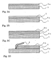
- a photochromic having a laminated film structure in which the ITO film is sandwiched between the two composite oxide films is formed.
- a first composite oxide film 5a comprising tin oxide and magnesium oxide with a thickness of 0.4 ⁇ m is formed by the methods described in shown in Figs. 2A and 2B in First Embodiment at first.
- the ITO film 2 with a thickness of 0.2 ⁇ m is formed on the composite oxide film 5a using the sputtering method.
- Fig. 3A a first composite oxide film 5a comprising tin oxide and magnesium oxide with a thickness of 0.4 ⁇ m is formed by the methods described in shown in Figs. 2A and 2B in First Embodiment at first.
- the ITO film 2 with a thickness of 0.2 ⁇ m is formed on the composite oxide film 5a using the sputtering method.
- a second composite oxide film 5b comprising tin oxide and magnesium oxide with a thickness of 0.4 ⁇ m is formed on the ITO film 2 by the same method as forming the first composite oxide film 5a. Consequently, the photochromic comprising the ITO film 2 sandwiched between the two composite oxide films 5a and 5b is obtained.
- the ITO film 2a with a thickness of 0.2 ⁇ m is formed on the glass substrate 1 as shown in Fig. 4. Then, the composite oxide film 5 with a thickness of 0.4 ⁇ m is formed on the ITO film 2a, followed by forming the ITO film 2b with a thickness of 0.2 ⁇ m thereon.
- This photochromic is considered to have an inverse lamination structure to the structure shown in Fig. 3, wherein the composite oxide film is sandwiched between the ITO films.
- the laminated structures of the Second Embodiment having a sandwich structure of the composite oxide layer and ITO layer shown in Figs. 3 and 4, are preferable over the lamination film structure of the composite oxide film and ITO film, since the interfaces between the composite oxide and ITO increases.
- a photochromic material similar to the photochromic material as shown in a Third Embodiment below may be obtained as a fine powder by the steps comprising peeling the photochromic from the glass substrate 1 using a metallic scraper 6, and pulverizing the peeled film as shown in Fig. 3D.
- the photochromic in the First Embodiment may be used as a fine powder of the photochromic material by the same method as described above.
- Fig. 6 is a graph showing the transmittance of the photochromic obtained in the Second Embodiment.
- the graph shows data of the transmittance of the photochromic before and after irradiating 365 nm UV light with a luminous energy of 30 mW/cm 2 for 5 minutes.
- the vertical axis shows the transmittance relative to the transmittance (%) of air as 100%, and the horizontal axis shows the wavelength of the light.
- the transmittance was measured with UV-31005 made by Shimadzu Co.
- the bold line indicates the transmittance before UV irradiation, and the slender line indicates the transmittance after UV irradiation.
- the transmittance at the wavelength of 550 nm decreased to 4.7% after UV irradiation from 86% before UV irradiation, and no changes of the transmittance were observed after leaving the irradiated photochromic under a room light for 6 months.
- the photochromic comprises a single layer.
- An application fluid is prepared by dissolving 10g each of tin caproate and magnesium caproate in 10g of ethyl alcohol, followed by dispersing 0.1g of a powder of ITO with a particle diameter of 0.04 ⁇ m.
- An application film is formed by applying the application fluid on the glass substrate 1 as a supporter as shown in Fig. 5A by the same method as in Fig. 2B.
- the glass substrate 1 After drying the application fluid, the glass substrate 1 is baked in a baking furnace at 400°C for 1 hour, thereby forming the photochromic 8 with a thickness of 0.4 ⁇ m comprising the tin-magnesium composite oxide film containing 0.04 ⁇ m of the ITO powder.
- a light transmission property equivalent to the light transmission property of the photochromic in Second Embodiment was obtained by irradiating UV light to the photochromic 8 thus formed.
- an application film was formed by applying an application fluid, prepared by dissolving 10g each of tin caproate and magnesium caproate in 10g of ethyl alcohol, on the glass substrate by the same method as in Fig. 2B. After drying the application fluid, the glass substrate was baked in a baking furnace at 400°C for 1 hour, and the composite oxide film formed was scraped from the glass substrate to form a scale-like powder with a size of about 1 ⁇ m.
- An application fluid was prepared by dissolving tin caproate and indium caproate in ethyl alcohol, and an application film was prepared by applying the application fluid and the scale-like powder material on the glass substrate by the same method as in Fig. 2B.
- the glass substrate was baked in a baking furnace at 400°C for 1 hour. UV light was irradiated to the composite oxide film formed as described above, and a light transmittance property equivalent to the light transmittance property shown in Second Embodiment was obtained.
- the photochromic material as shown in the First Embodiment and the Second Embodiment may be obtained by peeling these photochromics from the glass substrate 1 using a metallic scraper 6, and by pulverizing the peeled photochromic into a fine powder as shown in Fig. 5B.
- Fig. 4 shows an example of use of the scale-like photochromic material with a size of about 1 ⁇ m obtained in the First to Third Embodiments.
- the scale-like photochromic material was mixed with a solvent inert to the photochromic material, and the solution is applied on a sheet of paper 21 followed by drying.
- a binder may be appropriately mixed with the photochromic material so that the photochromic material is not peeled off.
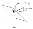
- the sheet of paper prepared as described above was scanned with a light from a UV light source 22 converged with a lens 23 to draw a pattern (character and picture) 24 on the sheet of paper 21 as shown in Fig. 7.
- the UV light source may be a laser diode or any other short wavelength light sources. Since the printing procedure is simplified as compared with the conventional Carlson process using a toner, the size, weight, cost and consumed electric power of the printing machine may be largely reduced.
- the pattern drawn in the method in Fig. 7 may be erased by passing the sheet of paper between hot rollers 31 as shown in Fig. 8. It is an advantage that recycling of the sheet of paper is facilitated since the pattern may be written again in the step shown in Fig. 7. An infrared laser may be irradiated for erasing the written pattern. The same drawing is possible by applying the photochromic material on a fabric in place of the sheet of paper.
- the photochromic material comprising the scale-like composite oxide may be mixed with an organic resin to form it into a sheet, or the sheet may be laminated with a sheet of metal, glass, ceramic and resin.
- a light-shielding glass for buildings may be produced by forming the photochromic according to the First to Third Embodiments on a sheet of soda lime glass, and by irradiating UV light by controlling the luminous energy of UV light so that an arbitrary illuminance of the light can permeate the glass.
- the light shielding film comprising the photochromic may be formed on a bottle for chemicals in place of forming on the sheet of glass, in order to use the bottle for preserving substances susceptible to light.
- a glass product having arbitrary color tone and gradation may be manufactured by adding pigments such as iron oxide, cobalt oxide and phthalocyanine in the application fluid. More complex color control is possible by drawing a pattern on the application film using an ethyl alcohol immediately after coating.
- the dim glass prepared by the method according to the present invention is excellent in mechanical strength, solvent resistance and heat resistance as compared with conventional glass products comprising a resin and pigment coated on the surface.
- a photochromic is modified from transparent to opaque by UV light irradiation, and opaque to transparent by heating, by forming a composite oxide comprising at least two elements as well as a transparent conductive material.
- the transparency of the photochromic is not changed under the room light.
Landscapes
- Chemical & Material Sciences (AREA)
- Engineering & Computer Science (AREA)
- Materials Engineering (AREA)
- Organic Chemistry (AREA)
- Laminated Bodies (AREA)
- Non-Silver Salt Photosensitive Materials And Non-Silver Salt Photography (AREA)
Abstract
Description
Claims (16)
- A photochromic comprising a laminated film including a composite oxide film composed of at least two elements selected from the group consisting of Ti, Mn, Co, Ni, Zn, and Sn, and the group consisting of Mg, Al, and Si, respectively, and a transparent conductive film, wherein a light transmission property of the photochromic is changed by UV irradiation.
- A photochromic comprising a laminated film including a composite oxide film composed of at least two elements selected from the group consisting of Ti, Mn, Co, Ni, Zn, and Sn, and the group consisting of Mg, Al, and Si, respectively, and a transparent conductive film, at least one of the composite oxide film and the transparent conductive film being formed on both faces of the other film, wherein a light transmission property of the photochromic is changed by UV irradiation.
- A photochromic comprising a film composed of a composite oxide of at least two elements selected from the group consisting of Ti, Mn, Co, Ni, Zn, and Sn, and the group consisting of Mg, Al and Si, respectively, the composite oxide containing transparent conductive particles.
- The photochromic according to claim 1 or 2, wherein the transparent conductive film comprises indium oxide as a main component.
- A photochromic material comprising a powder containing a composite oxide of at least two elements selected from the group consisting of Ti, Mn, Co, Ni, Zn, and Sn, and the group consisting of Mg, Al and Si, respectively, the composite oxide containing transparent conductive particles.
- The photochromic or the photochromic material, as the case may be, according to any preceding claim, wherein the composite oxide comprises tin and magnesium.
- The photochromic or the photochromic material, as the case may be, according to claim 6, wherein the ratio of the number of tin atoms to the number of magnesium atoms contained in the composite oxide is in the range of 3:7 to 7:3.
- The photochromic or the photochromic material, as the case may be, according to claim 7, wherein the proportion of defects of oxygen atoms in the composite oxide is 1% to 70%.
- The photochromic or the photochromic material, as the case may be, according to claim 3 or 5 or any one of claims 6 to 8 when read as appended to claim 3 or 5, wherein the transparent conductive particles comprise indium oxide as a main component.
- A method for manufacturing a photochromic material, comprising pulverizing the laminate film according to claim 1 or 2 to form a powdery photochromic material.
- A method of manufacturing a photochromic, comprising forming a compound oxide film according to claim 1 or 2 by a process selected from a coating-pyrolysis process, a sol-gel process, a CVD process, a vapor deposition process, an ion plating process, and a sputtering process.
- A method of manufacturing a photochromic according to claim 1 or 2, wherein the compound oxide film is formed by a coating-pyrolysis process using a fatty acid salt or a fatty acid salt derivative as a raw material.
- A method of manufacturing a photochromic, comprising forming a compound oxide film according to claim 3 by a process selected from a coating-pyrolysis process, and a sol-gel process.
- A method of manufacturing a photochromic according to claim 3, wherein the compound oxide film is formed by a coating-pyrolysis process using a fatty acid salt or a fatty acid salt derivative as a raw material.
- A photochromic according to any one of claims 1 to 3, wherein a portion is irradiated with light at a wavelength of 500 nm or less to form an opaque irradiated portion.
- A photochromic according to claim 15, wherein the opaque portion formed by ultraviolet irradiation becomes transparent by heating.
Applications Claiming Priority (4)
| Application Number | Priority Date | Filing Date | Title |
|---|---|---|---|
| JP2002159484 | 2002-05-31 | ||
| JP2002159484 | 2002-05-31 | ||
| JP2002348598A JP4188672B2 (en) | 2002-05-31 | 2002-11-29 | Photochromic body, photochromic material and method for producing the same |
| JP2002348598 | 2002-11-29 |
Publications (2)
| Publication Number | Publication Date |
|---|---|
| EP1367112A2 true EP1367112A2 (en) | 2003-12-03 |
| EP1367112A3 EP1367112A3 (en) | 2006-11-08 |
Family
ID=29422470
Family Applications (1)
| Application Number | Title | Priority Date | Filing Date |
|---|---|---|---|
| EP03253428A Withdrawn EP1367112A3 (en) | 2002-05-31 | 2003-05-30 | Photochromics, photochromic materials and methods for manufacturing the same |
Country Status (6)
| Country | Link |
|---|---|
| US (2) | US7041392B2 (en) |
| EP (1) | EP1367112A3 (en) |
| JP (1) | JP4188672B2 (en) |
| KR (1) | KR20030094035A (en) |
| CN (1) | CN1257952C (en) |
| TW (1) | TWI242598B (en) |
Families Citing this family (11)
| Publication number | Priority date | Publication date | Assignee | Title |
|---|---|---|---|---|
| CN1333039C (en) * | 2005-01-05 | 2007-08-22 | 中国科学院化学研究所 | Photochromic material capable of using in blue light storage |
| CN100358159C (en) * | 2005-02-28 | 2007-12-26 | 浙江大学 | Thin film material for sunlight blind area ultraviolet detector and its producing method |
| AU2007214373B2 (en) * | 2006-09-01 | 2010-05-20 | Aristocrat Technologies Australia Pty Ltd | Gaming apparatus and method with dependent feature game |
| CN102540606B (en) * | 2006-11-02 | 2014-12-10 | 刮拉技术有限公司 | Metallic oxide and method for changing structure of metallic oxide |
| CN101668714A (en) * | 2007-04-09 | 2010-03-10 | Lg化学株式会社 | multi-layered photochromic sheet and photochromic glass prepared therefrom |
| JP5141794B2 (en) * | 2011-06-10 | 2013-02-13 | 三菱マテリアル株式会社 | Transparent conductive film for organic EL and organic EL element using this transparent conductive film |
| US9019584B2 (en) * | 2012-03-12 | 2015-04-28 | Empire Technology Development Llc | Holographic image reproduction mechanism using ultraviolet light |
| US9365314B2 (en) | 2012-11-16 | 2016-06-14 | Owens-Brockway Glass Container Inc. | Product and package with a photosensitive use-evident feature |
| US9367849B1 (en) | 2015-05-21 | 2016-06-14 | Owens-Brockway Glass Container Inc. | Packaging authentication |
| CN110752241B (en) * | 2019-10-31 | 2023-01-10 | 武汉天马微电子有限公司 | Display panel and display device |
| KR102390830B1 (en) * | 2019-12-20 | 2022-04-25 | 주식회사 포스코 | Annealing separating agent composition for grain oriented electrical steel sheet, grain oriented electrical steel sheet, and method for manufacturing the same |
Family Cites Families (9)
| Publication number | Priority date | Publication date | Assignee | Title |
|---|---|---|---|---|
| JPH0611870B2 (en) * | 1986-06-27 | 1994-02-16 | 徳山曹達株式会社 | Inorganic compound / dye composite particles |
| JP3053667B2 (en) * | 1991-06-10 | 2000-06-19 | 株式会社資生堂 | Photochromic ultraviolet shielding powder, method for producing the same, and external preparation for skin |
| TW288044B (en) * | 1993-05-12 | 1996-10-11 | Sumitomo Chemical Co | |
| JP3330610B2 (en) * | 1994-01-24 | 2002-09-30 | 触媒化成工業株式会社 | Photochromic composite oxide and cosmetic containing the photochromic composite oxide |
| US5604626A (en) * | 1995-02-10 | 1997-02-18 | Donnelly Corporation | Photochromic devices |
| JP3840664B2 (en) * | 1996-04-26 | 2006-11-01 | セイコーエプソン株式会社 | Coating composition |
| WO2000071482A1 (en) * | 1999-05-25 | 2000-11-30 | Asahi Glass Company, Limited | Photochromic glass and method for preparation thereof |
| CN1211446C (en) * | 1999-12-06 | 2005-07-20 | 株式会社德山 | Coating composition and method for preparation thereof |
| JP3772194B2 (en) * | 2000-08-31 | 2006-05-10 | 独立行政法人産業技術総合研究所 | Light limiting material |
-
2002
- 2002-11-29 JP JP2002348598A patent/JP4188672B2/en not_active Expired - Fee Related
-
2003
- 2003-05-15 US US10/438,951 patent/US7041392B2/en not_active Expired - Fee Related
- 2003-05-19 TW TW092113461A patent/TWI242598B/en not_active IP Right Cessation
- 2003-05-30 KR KR10-2003-0034657A patent/KR20030094035A/en not_active Ceased
- 2003-05-30 CN CNB031385141A patent/CN1257952C/en not_active Expired - Fee Related
- 2003-05-30 EP EP03253428A patent/EP1367112A3/en not_active Withdrawn
-
2006
- 2006-03-07 US US11/369,789 patent/US7335322B2/en not_active Expired - Fee Related
Also Published As
| Publication number | Publication date |
|---|---|
| US7335322B2 (en) | 2008-02-26 |
| CN1257952C (en) | 2006-05-31 |
| US7041392B2 (en) | 2006-05-09 |
| CN1467261A (en) | 2004-01-14 |
| TWI242598B (en) | 2005-11-01 |
| TW200404886A (en) | 2004-04-01 |
| KR20030094035A (en) | 2003-12-11 |
| JP4188672B2 (en) | 2008-11-26 |
| US20060151757A1 (en) | 2006-07-13 |
| JP2004050808A (en) | 2004-02-19 |
| EP1367112A3 (en) | 2006-11-08 |
| US20030224219A1 (en) | 2003-12-04 |
Similar Documents
| Publication | Publication Date | Title |
|---|---|---|
| DE69626805T2 (en) | Translucent substrates with anti-reflective coatings | |
| US7041392B2 (en) | Photochromic, photochromic material and method for manufacturing the same | |
| Messina et al. | Antimony sulfide thin films in chemically deposited thin film photovoltaic cells | |
| US6897560B2 (en) | Ultraviolet-transparent conductive film and process for producing the same | |
| DE69622831T2 (en) | Transparent, conductive laminate and electroluminescent element | |
| Lin et al. | Efficient cesium lead halide perovskite solar cells through alternative thousand‐layer rapid deposition | |
| DE10336041A1 (en) | Optical layer system with antireflection properties | |
| US5667888A (en) | Color filters and methods of manufacturing the same | |
| JP2002341111A (en) | Functional thin films with optical and electrical properties | |
| Oyama et al. | Low resistance indium tin oxide films on large scale glass substrate | |
| DE202012013088U1 (en) | Plant for coating and heat treatment | |
| Girtan et al. | Influence of oxidation conditions on the properties of indium oxide thin films | |
| US9040119B2 (en) | Method for producing transparent conductive film, transparent conductive film, transparent conductive substrate and device comprising the same | |
| CN102603204A (en) | Photochromic glass | |
| Tomás et al. | Effect of ZnSe doping on the photochromic and thermochromic properties of MoO3 thin films | |
| DE69904137T2 (en) | Layer based on a conductive metal oxide | |
| Kala et al. | Structural and luminescence studies on TiO2-MoO3 thin films | |
| JP2528763B2 (en) | Transparent electrically conductive oxide | |
| Kim | Deposition of indium tin oxide films on polycarbonate substrates by direct metal ion beam deposition | |
| KR101090692B1 (en) | Touch Panel Film and Method for Preparing the Same | |
| Reddy et al. | Facile synthesis and characterization of PbS thin films doped with various aluminum concentrations for photovoltaic applications | |
| KR20160022148A (en) | Transparent electrode and method for manufacturing the same | |
| JP2958384B2 (en) | Method for producing multilayer film including transparent conductor film | |
| JP2005181642A (en) | Photochromic device and manufacturing method thereof | |
| Chen et al. | Effects of different annealing temperature on the optoelectrical properties of MGZO thin films prepared by co-sputtering method |
Legal Events
| Date | Code | Title | Description |
|---|---|---|---|
| PUAI | Public reference made under article 153(3) epc to a published international application that has entered the european phase |
Free format text: ORIGINAL CODE: 0009012 |
|
| AK | Designated contracting states |
Kind code of ref document: A2 Designated state(s): AT BE BG CH CY CZ DE DK EE ES FI FR GB GR HU IE IT LI LU MC NL PT RO SE SI SK TR |
|
| AX | Request for extension of the european patent |
Extension state: AL LT LV MK |
|
| PUAL | Search report despatched |
Free format text: ORIGINAL CODE: 0009013 |
|
| AK | Designated contracting states |
Kind code of ref document: A3 Designated state(s): AT BE BG CH CY CZ DE DK EE ES FI FR GB GR HU IE IT LI LU MC NL PT RO SE SI SK TR |
|
| AX | Request for extension of the european patent |
Extension state: AL LT LV MK |
|
| 17P | Request for examination filed |
Effective date: 20070502 |
|
| 17Q | First examination report despatched |
Effective date: 20070608 |
|
| AKX | Designation fees paid |
Designated state(s): DE FR GB |
|
| RAP1 | Party data changed (applicant data changed or rights of an application transferred) |
Owner name: SHINODA PLASMA CORPORATION |
|
| STAA | Information on the status of an ep patent application or granted ep patent |
Free format text: STATUS: THE APPLICATION IS DEEMED TO BE WITHDRAWN |
|
| 18D | Application deemed to be withdrawn |
Effective date: 20101201 |