EP1367019B1 - Both-way movable body driving mechanism and elevator device using the same - Google Patents
Both-way movable body driving mechanism and elevator device using the same Download PDFInfo
- Publication number
- EP1367019B1 EP1367019B1 EP02712336.3A EP02712336A EP1367019B1 EP 1367019 B1 EP1367019 B1 EP 1367019B1 EP 02712336 A EP02712336 A EP 02712336A EP 1367019 B1 EP1367019 B1 EP 1367019B1
- Authority
- EP
- European Patent Office
- Prior art keywords
- tension member
- belt
- movable body
- sheave
- rollers
- Prior art date
- Legal status (The legal status is an assumption and is not a legal conclusion. Google has not performed a legal analysis and makes no representation as to the accuracy of the status listed.)
- Expired - Lifetime
Links
- 230000005540 biological transmission Effects 0.000 claims description 7
- 239000000463 material Substances 0.000 claims description 3
- 238000005299 abrasion Methods 0.000 claims description 2
- 239000002344 surface layer Substances 0.000 claims description 2
- 230000014509 gene expression Effects 0.000 description 10
- 238000010276 construction Methods 0.000 description 5
- 230000006835 compression Effects 0.000 description 3
- 238000007906 compression Methods 0.000 description 3
- 239000010410 layer Substances 0.000 description 3
- 239000004952 Polyamide Substances 0.000 description 1
- 239000004760 aramid Substances 0.000 description 1
- 229920003235 aromatic polyamide Polymers 0.000 description 1
- 230000001419 dependent effect Effects 0.000 description 1
- 238000010586 diagram Methods 0.000 description 1
- 230000003292 diminished effect Effects 0.000 description 1
- 239000011796 hollow space material Substances 0.000 description 1
- 238000009434 installation Methods 0.000 description 1
- 229920001084 poly(chloroprene) Polymers 0.000 description 1
- 229920002647 polyamide Polymers 0.000 description 1
- 230000002035 prolonged effect Effects 0.000 description 1
- 238000009877 rendering Methods 0.000 description 1
- 239000002759 woven fabric Substances 0.000 description 1
Images



Classifications
-
- B—PERFORMING OPERATIONS; TRANSPORTING
- B66—HOISTING; LIFTING; HAULING
- B66B—ELEVATORS; ESCALATORS OR MOVING WALKWAYS
- B66B11/00—Main component parts of lifts in, or associated with, buildings or other structures
- B66B11/0035—Arrangement of driving gear, e.g. location or support
- B66B11/0045—Arrangement of driving gear, e.g. location or support in the hoistway
- B66B11/0055—Arrangement of driving gear, e.g. location or support in the hoistway on the counterweight
-
- B—PERFORMING OPERATIONS; TRANSPORTING
- B66—HOISTING; LIFTING; HAULING
- B66B—ELEVATORS; ESCALATORS OR MOVING WALKWAYS
- B66B11/00—Main component parts of lifts in, or associated with, buildings or other structures
- B66B11/04—Driving gear ; Details thereof, e.g. seals
-
- B—PERFORMING OPERATIONS; TRANSPORTING
- B66—HOISTING; LIFTING; HAULING
- B66B—ELEVATORS; ESCALATORS OR MOVING WALKWAYS
- B66B11/00—Main component parts of lifts in, or associated with, buildings or other structures
- B66B11/0065—Roping
- B66B11/008—Roping with hoisting rope or cable operated by frictional engagement with a winding drum or sheave
-
- B—PERFORMING OPERATIONS; TRANSPORTING
- B66—HOISTING; LIFTING; HAULING
- B66B—ELEVATORS; ESCALATORS OR MOVING WALKWAYS
- B66B11/00—Main component parts of lifts in, or associated with, buildings or other structures
- B66B11/04—Driving gear ; Details thereof, e.g. seals
- B66B11/043—Driving gear ; Details thereof, e.g. seals actuated by rotating motor; Details, e.g. ventilation
- B66B11/0476—Driving gear ; Details thereof, e.g. seals actuated by rotating motor; Details, e.g. ventilation with friction gear, e.g. belt linking motor to sheave
-
- B—PERFORMING OPERATIONS; TRANSPORTING
- B66—HOISTING; LIFTING; HAULING
- B66B—ELEVATORS; ESCALATORS OR MOVING WALKWAYS
- B66B9/00—Kinds or types of lifts in, or associated with, buildings or other structures
- B66B9/02—Kinds or types of lifts in, or associated with, buildings or other structures actuated mechanically otherwise than by rope or cable
-
- B—PERFORMING OPERATIONS; TRANSPORTING
- B66—HOISTING; LIFTING; HAULING
- B66B—ELEVATORS; ESCALATORS OR MOVING WALKWAYS
- B66B9/00—Kinds or types of lifts in, or associated with, buildings or other structures
- B66B9/02—Kinds or types of lifts in, or associated with, buildings or other structures actuated mechanically otherwise than by rope or cable
- B66B9/027—Kinds or types of lifts in, or associated with, buildings or other structures actuated mechanically otherwise than by rope or cable by rope climbing devices
Definitions
- the present invention relates to a mechanism for reciprocatingly driving a reciprocatingly movable body, and elevator apparatus comprising a mechanism for reciprocatingly driving a cage which is reciprocatingly movably disposed in a path of reciprocating movement.
- a lift drive mechanism which comprises, as shown in FIG. 24 , a plurality of ropes 3 reeved around a plurality of sheaves, such as a traction sheave 9 rotatingly driven by a drive motor 91 and direction changing sheaves 4, 43 attached to a cage 1 and a counterweight 2, and having fixed opposite ends 31, 32 for moving the cage 1 and the counterweight 2 upward or downward in opposite directions to each other.
- the cage 1, counterweight 2 and lift drive mechanism described are arranged in a lift path 10, the cage 1 is guided by guide rails 14, 14 for upward or downward movement, and the counterweight 2 is guided by guide rails 15, 15 for upward or downward movement as shown in FIG. 25 .
- the drive motor 91 has connected thereto an unillustrated control circuit for controlling the upward and downward movement of the cage 1 and stopping of a cage door 11 at a position coinciding with a floor door 12.
- the tension T1 on the slack side is due to the weight of the cage 1.
- the tension T1 is small, and the rope 3 is likely to slip, failing to satisfy the relationship of Mathematical Expression 1.
- the cage 1 itself has weight of 1500 Kg
- the loading capacity of the cage is 1000 Kg
- the weight of the counterweight 2 is the weight of the cage 1 plus 50% of the loading capacity.
- the left side member of Expression 1 has the following values when the weight of load is zero and when the cage is fully loaded.
- An example of mechanism for reciprocatingly driving a moveable body is known from UA-A-5921352 .
- An object of the present invention is to overcome all the foregoing problems by providing a drive mechanism capable of reciprocatingly driving a cage or like movable body without using any traction sheave and an elevator apparatus of the novel reciprocating drive type having the drive mechanism incorporated therein.
- the present invention provides a reciprocatingly movable body drive mechanism which comprises a tension member in the form of a rope or belt for reciprocatingly driving a reciprocatingly movable body, and a drive device for driving the tension member longitudinally thereof while pressing a specified region of the tension member sideways in contact with the tension member.
- the drive device is in contact with a circular-arc region of the tension member as reeved around a sheave for pressing the circular-arc region against the sheave.
- the drive device drives the tension member by frictional contact therewith to thereby reciprocatingly drive the movable body.
- the drive device can be provided by a belt transmission disposed alongside the tension member and revolvingly movable along a tension member extension route, a pressing mechanism for pressing a belt surface of the belt transmission into contact with the tension member, and a drive motor for driving the belt transmission.
- the present invention provides an elevator apparatus which comprises a reciprocatingly movable body reciprocatingly movably provided in a path of reciprocating movement, and a mechanism for reciprocatingly driving the body.
- the reciprocatingly driving mechanism comprises a sheave disposed at a predetermined level, a tension member in the form of a rope or belt and extending along a path around the sheave, and a drive device for driving the tension member in engagement therewith by pressing a specified longitudinal region of the tension member sideways.
- the term "reciprocatingly movable body” means a cage having a passenger compartment or cargo compartment, and refers to a concept superior to that of a counterweight as a counterpart of the cage.
- tension member refers to a concept superior to that of one or a plurality of ropes or belts.
- reciprocating movement includes a reciprocating movement in a vertical direction, horizontal direction, oblique direction or direction along a bent or curved path.
- the drive device Usable as the drive device is a drive device which drives the tension member as reeved around at least one sheave disposed along the tension member extension route by pressing a circular-arc region of the tension member against the sheave typer be used.
- a device comprising a belt pressed against the circular-arc region of the tension member and revolvingly movable, a plurality of rollers arranged along a path of revolving movement of the belt, and a drive motor for rotatingly driving at least one of the rollers.
- the belt is driven by the drive motor, whereby the tension member is driven by frictional contact with the surface of the belt.
- the reciprocatingly movable body is reciprocatingly moved.
- the tension member can be prevented from slipping under the condition expressed by Mathematical Expression 4 given below, wherein T1 is the tension acting on the slack side of the tension member extending from the drive device toward opposite directions, T2 is the tension on the tensioned side of the tension member, ⁇ is the coefficient of friction between the belt surface of the belt transmission and the tension member, and N is the pressure exerted by the belt surface on the tension member.
- T1 is the tension acting on the slack side of the tension member extending from the drive device toward opposite directions
- T2 is the tension on the tensioned side of the tension member
- ⁇ is the coefficient of friction between the belt surface of the belt transmission and the tension member
- N is the pressure exerted by the belt surface on the tension member.
- the tension T1 on the slack side is due to the weight of the reciprocatingly movable body (cage)
- the tension T1 is small if the cage carries a small number of passengers
- the relationship of Mathematical Expression 4 can be satisfied by increasing the pressure N. The tension member can then be prevented from slipping.
- the cage itself has weight of 1500 Kg
- the loading capacity is 1000 Kg
- the weight of the counterweight is the weight of the cage itself plus 50% of the loading capacity as exemplified above.
- the left side member (T2-T1) of Mathematical Expression 4 to be satisfied has a constant value even if the weight of the cage itself or the weight of load varies.
- the cage can be moved upward or downward without permitting slippage of the tension member if the drive device exerts a drive force greater than this value when driving the tension member in frictional contact therewith.
- the drive device of the circular-arc drive type comprises a mechanism for tensioning the belt. This effectively presses the belt into contact with the tension member to produce a great frictional force between the belt and the tension member.
- the tensioning mechanism comprises a frame 130 supported so as to be movable toward or away from the sheave, the plurality of rollers being rotatably supported by the frame 130, and the tension member has one end connected to a free end of the frame 130.
- the frame 130 is driven toward the sheave by the tension of the tension member, and the belt extending over the rollers is pressed into contact with the circular-arc region of the tension member as reeved around the sheave. Consequently, the belt can be given sufficiently great tension at all times. Accordingly, the tensioning mechanism requires no special power source and consequently becomes simple in construction.
- the tensioning mechanism comprises a frame 130 supported so as to be movable toward or away from the sheave, the plurality of rollers being rotatably supported by the frame 130, and a lever mechanism 140 is provided between a free end of the frame 130 and one end of the tension member.
- the lever mechanism 140 converts the tension of the tension member to a force for driving the frame 130, with the portion of the lever mechanism 140 connected to the end of the tension member serving as a fulcrum and with the portion thereof opposed to the free end of the frame 130 serving as the point of application. In this way, the tension of the belt is adjusted to an acting force of required magnitude.
- the tensioning mechanism comprises an arm 156 supported so as to be movable toward or away from the sheave, the arm 156 being elastically biased toward a direction away from the sheave, and a plurality of rollers included among the plurality of rollers and positioned at opposite ends of the arrangement of rollers are rotatably supported each at a predetermined level relative to the sheave, the arm 156 rotatably supporting thereon one or more rollers positioned inwardly of the roller arrangement.
- the arm 156 is biased toward a direction away from the sheave, whereby the inward roller or rollers are driven away from the sheave to tension the belt.
- the elevator apparatus of the invention described above has a drive device for driving a tension member in frictional contact therewith. This obviates the need for driving by a traction sheave, rendering the cage or like reciprocatingly movable body smaller in weight and consequently permitting use of a compacted lightweight lift drive mechanism.
- FIGS. 15 to 22 show examples of elevator apparatus of the invention wherein a drive device of the circular-arc drive type is used.
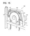
- FIG. 15 shows a drive device 100, which is provided along a sheave 42 disposed at a specified level within a path of movement of the elevator.
- the drive device 100 comprises a belt 102 reeved around four rollers 101, 101, 101, 101a arranged along the outer periphery of the sheave 42, and a motor 103 coupled to the roller 101a among the rollers.
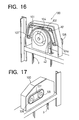
- FIG. 16 shows a drive device 100 having a motor 104 serving as a drive source and installed in a hollow space formed in the center of a sheave 42.
- a drive pulley 105 is mounted on the output shaft of the motor 104, and the rotation of the drive pulley 105 is transmitted to a driven pulley 106 by a belt 107 as seen in FIG. 17 .
- a roller 101a shown in FIG. 16 is connected to the driven pulley 106. The rotation of the motor 104 is transmitted to the roller 101a via the drive pulley 105, belt 107 and driven pulley 106, whereby a belt 102 is rotated revolvingly to drive ropes 3 in frictional contact therewith.
- FIG. 18 shows a drive device 100, wherein a belt 111 is reeved around two rollers 110, 110, and a motor 112 is coupled to one of the rollers 110.
- a belt 111 is reeved around two rollers 110, 110, and a motor 112 is coupled to one of the rollers 110.
- About one-half of the circumferential length of the belt 111 is curved in a circular-arc form along the outer periphery of a sheave 42, pressing circular-arc regions of ropes 3 as reeved around the sheave 42 against the sheave 42.
- the belt 111 is revolvingly moved by driving the motor 112
- the ropes 3 are driven by a frictional force acting between the belt 111 and the ropes 3.
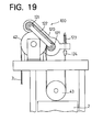
- a drive device 100 shown in FIG. 19 comprises a belt 122 reeved around two rollers 121, 121.
- the two rollers 121, 121 are rotatably supported by a frame 120, which is supported so as to be movable toward or away from a sheave 42.
- the frame 120 has a free end carrying a rope socket 124 thereon, with a compression spring 123 acting therebetween.
- Joined to the rope socket 124 is one end of a rope 3 extending around a sheave 43 for a counterweight 2.
- the tension of the rope 3 acts on the frame 120 of the drive device 100, driving the two rollers 121, 121 toward the sheave 42.
- the belt 122 is strongly pressed into contact with a circular-arc region of the rope 3 as reeved around the sheave 42, thereby giving sufficiently great tension to the belt 122.
- a great frictional force is produced between the belt 122 and the rope 3, driving the rope 3 without causing slippage between the rope and the belt 122.
- a drive device 100 shown in FIG. 20 comprises a belt 132 extending around four rollers 131, 131, 131, 131. These rollers 131, 131, 131, 131 are rotatably supported on a frame 130, which is supported so as to be movable toward or away from a sheave 42.
- the frame 130 has a free end, to which a rope socket 124 is attached, with a compression spring 123 acting therebetween.
- Joined to the rope socket 124 is one end of a rope 3 extending around a sheave 43 for a counterweight 2.
- the tension of the rope 3 acts on the frame 130 of the drive device 100, driving the four rollers 131, 131, 131, 131 toward the sheave 42.
- the belt 132 is strongly pressed into contact with a circular-arc region of the rope 3 as reeved around the sheave 42, thereby giving sufficiently great tension to the belt 132.
- a great frictional force is produced between the belt 132 and the rope 3, driving the rope 3 without causing slippage between the rope and the belt 132.
- FIG. 21 shows a drive device 100 corresponding to the drive device shown in FIG. 20 , in which a lever mechanism 140 is interposed between the free end of the frame 130 of the device and one end of the rope 3.
- the lever mechanism 140 has an arm portion 140a carrying a rope socket 124, with a compression spring 123 acting therebetween.
- One end of the rope 3 is joined to the rope socket 124.
- the lever mechanism 140 converts the tension of the rope 3 to a force for driving the frame 130, with the portion of the lever mechanism 140 connected to the end of the rope 3 serving as a fulcrum and with the portion thereof opposed to the free end of the frame 130 serving as the point of application. In this way, the tension to be given to the belt 132 is adjusted to a suitable magnitude.
- FIG. 22 shows a drive device 100, wherein a pivotal arm 156 is disposed above a sheave 42.
- the pivotal arm 156 has a base end supported by a pivot 157 positioned at a specified level on a beam 150, and a forward end 158 of the pivotal arm 156 biased upward by a spring 159.
- Four rollers 151, 152, 153, 154 are provided with a belt 155 reeved therearound and positioned around the sheave 42.
- the two rollers 151, 154 at opposite sides are rotatably supported by the beam 150 and positioned each at a specified level, and the two inward rollers 152, 153 are rotatably supported by the pivotal arm 156.
- the pivotal arm 156 is biased counterclockwise by the spring 159, whereby the inward two rollers 152, 153 are pushed up to tension the belt 155.
- FIG. 23 shows another drive device 100, wherein a sheave 42 is attached to a frame 160, and rollers 161, 162, 163 are arranged respectively at three locations, i.e., above and at opposite sides of the sheave 42.
- a belt 164 is reeved around these rollers 161, 162, 163 for pressing ropes 3 as reeved around the sheave 42 against the sheave 42 by the belt 164.
- Coupled to the upper roller 161 is a motor (not shown) mounted on the rear side of the frame 160.
- the rollers 162, 163 at opposite sides are each mounted so as to be adjustable in level by a position adjusting mechanism 165.
- the tension of the belt 164 is adjustable by varying the level.
- the maximum values of specific pressures of the rope surface and the belt surface are respectively about 2 MPa and about 1 MPa in the case of the circular-arc drive type. This serves to preclude the damage to be caused to the belt and the rope to ensure a prolonged life.
- the belt constituting the drive device of the circular-arc drive type is pressed against the circular-arc region of the rope by virtue of the tension thereof.
- the belt can therefore be smaller in thickness than when the belt is pressed by pressing rollers of small diameter as is the case with the drive device of the straight drive type.
- the rollers for driving the belt can be reduced in diameter and the drive motor to be used can be of smaller capacity.
- the noise to be produced by the drive device of the circular-arc drive type is much smaller, while the device can be maintained satisfactorily.
- the mechanism or apparatus of the present invention is not limited to the foregoing embodiments in construction but can be modified variously within the technical scope defined in the appended claims.
- the belt to be brought into frictional contact with the rope for driving need not always have a recessed curved contact face which is circular-arc in cross section, but a grooved surface of V-shaped cross section or one of various other cross sections is similarly useful.
- the belt for driving the rope by frictional contact therewith can be composed of a plurality of belt pieces divided in a direction orthogonal to the longitudinal direction of the rope 3 so as to use each of the belt pieces in contact with one or a plurality of ropes 3.
- a core having high tension and high strength can be incorporated in the belt for driving the rope by frictional contact therewith, and the belt surface layer to be in contact with the rope can be made from a material having abrasion resistance.
- a belt of multilayer structure is useful which comprises, for example, a layer of chloroprene rubber, a layer of polyamide woven fabric and a layer of aramid cord. If the materials to be used for the rope and the belt have the same modulus of longitudinal elasticity (spring constant), diminished slippage will result between the two members. The advantage of suppressed wear is then available.
- a tension member in the form of a belt can be used in place of the rope 3 serving as a tension member.
- Use of a belt having the same structure as described above especially leads to the same modulus of longitudinal elasticity (spring constant) between the belts to be in contact with each other, and to the advantage of reduced slippage and suppressed wear.
- the motor for driving the belt need not always be coupled to the center shaft of the roller as shown in FIG. 2 or 15 , but can be housed in the roller for driving the roller from inside.
- the drive device of only one type i.e., the drive device 5 of the straight drive type or the drive device 100 of the circular-arc drive type, can be installed at each of a plurality of locations, or devices of the both types can be used in combination.
- the reciprocatingly movable body drive mechanism of the invention is not limited only for use in elevator apparatus of the type movable upward or downward wherein a cage and a counterweight are arranged at opposite sides as described above, but can be used also in elevator apparatus of the horizontally movable type, elevator apparatus wherein cages are arranged respectively on opposite sides, cable railways, ropeways, etc.
Landscapes
- Engineering & Computer Science (AREA)
- Mechanical Engineering (AREA)
- Structural Engineering (AREA)
- Civil Engineering (AREA)
- Automation & Control Theory (AREA)
- Cage And Drive Apparatuses For Elevators (AREA)
- Transmission Devices (AREA)
- Lift-Guide Devices, And Elevator Ropes And Cables (AREA)
Description
- The present invention relates to a mechanism for reciprocatingly driving a reciprocatingly movable body, and elevator apparatus comprising a mechanism for reciprocatingly driving a cage which is reciprocatingly movably disposed in a path of reciprocating movement.
- For use in such elevator apparatus, a lift drive mechanism is already known which comprises, as shown in
FIG. 24 , a plurality ofropes 3 reeved around a plurality of sheaves, such as atraction sheave 9 rotatingly driven by adrive motor 91 anddirection changing sheaves cage 1 and acounterweight 2, and having fixedopposite ends 31, 32 for moving thecage 1 and thecounterweight 2 upward or downward in opposite directions to each other. - With the elevator apparatus described, the
cage 1,counterweight 2 and lift drive mechanism described are arranged in alift path 10, thecage 1 is guided byguide rails counterweight 2 is guided byguide rails FIG. 25 . Thedrive motor 91 has connected thereto an unillustrated control circuit for controlling the upward and downward movement of thecage 1 and stopping of acage door 11 at a position coinciding with afloor door 12. - With the conventional elevator apparatus shown in
FIGS. 24 and25 , therope 3 reeved around thetraction sheave 9 must move with the rotation of thesheave 9 without slipping relative to thesheave 9 while thetraction sheave 9 is being rotated by thedrive motor 91 to move thecage 1 upward or downward. For this reason, the prior art has encountered problems such as difficulty in reducing the weight of thecage 1. - To render the
rope 3 of the conventional elevator apparatus reeved around thetraction sheave 9 free of slipping in the case where therope 3 is subjected to tension T1 on the slack side thereof and to tension T2 on the tensioned side thereof as shown inFIG. 26 , the relationship of Mathematical Expression 1 (Eytelwein) needs to be satisfied, assuming that the coefficient of friction between thetraction sheave 9 and therope 3 is µ and that the angle of therope 3 reeved around thesheave 9 is θ.
- Suppose the tension T1 on the slack side is due to the weight of the
cage 1. When a small number of passengers are in thecage 1, the tension T1 is small, and therope 3 is likely to slip, failing to satisfy the relationship ofMathematical Expression 1. For example, suppose thecage 1 itself has weight of 1500 Kg, the loading capacity of the cage is 1000 Kg, and the weight of thecounterweight 2 is the weight of thecage 1 plus 50% of the loading capacity. The left side member ofExpression 1 has the following values when the weight of load is zero and when the cage is fully loaded.
- If the weight of the
cage 1 itself is then reduced to 1000 Kg, the values ofMathematical Expressions 2 are as follows.
- Thus, a change in the weight of the cage itself or in the weight of load greatly varies the value of the left side member (T2/T1) of
Expression 1 to be satisfied. This value increases especially with a reduction in the weight of thecage 1, giving rise to the problem that thecage 1 cannot be reduced in weight. - It is therefore conventional practice to attach a weight to the
cage 1 so as not to permit therope 3 to slip even when the cage carries a small number of passengers. This gives increased weight to thecage 1 itself. The increase in the weight of thecage 1 itself gives rise to the problem of making the lift drive mechanism large-sized and heavier. Furthermore, thedrive motor 91 serving as the power source for the lift drive mechanism is given an increased capacity, consequently resulting in increased power consumption and also entailing the problem of necessitating space for the installation of thedrive motor 91 which becomes greater in size. - An example of mechanism for reciprocatingly driving a moveable body is known from
UA-A-5921352 - An object of the present invention is to overcome all the foregoing problems by providing a drive mechanism capable of reciprocatingly driving a cage or like movable body without using any traction sheave and an elevator apparatus of the novel reciprocating drive type having the drive mechanism incorporated therein.
- The present invention provides a reciprocatingly movable body drive mechanism which comprises a tension member in the form of a rope or belt for reciprocatingly driving a reciprocatingly movable body, and a drive device for driving the tension member longitudinally thereof while pressing a specified region of the tension member sideways in contact with the tension member. The drive device is in contact with a circular-arc region of the tension member as reeved around a sheave for pressing the circular-arc region against the sheave. With the drive mechanism, the drive device drives the tension member by frictional contact therewith to thereby reciprocatingly drive the movable body.
- For example, the drive device can be provided by a belt transmission disposed alongside the tension member and revolvingly movable along a tension member extension route, a pressing mechanism for pressing a belt surface of the belt transmission into contact with the tension member, and a drive motor for driving the belt transmission.
- The present invention provides an elevator apparatus which comprises a reciprocatingly movable body reciprocatingly movably provided in a path of reciprocating movement, and a mechanism for reciprocatingly driving the body. The reciprocatingly driving mechanism comprises a sheave disposed at a predetermined level, a tension member in the form of a rope or belt and extending along a path around the sheave, and a drive device for driving the tension member in engagement therewith by pressing a specified longitudinal region of the tension member sideways. The term "reciprocatingly movable body" means a cage having a passenger compartment or cargo compartment, and refers to a concept superior to that of a counterweight as a counterpart of the cage. The term "tension member" refers to a concept superior to that of one or a plurality of ropes or belts. The term "reciprocating movement" includes a reciprocating movement in a vertical direction, horizontal direction, oblique direction or direction along a bent or curved path.
- Usable as the drive device is a drive device which drives the tension member as reeved around at least one sheave disposed along the tension member extension route by pressing a circular-arc region of the tension member against the sheave typer be used.
- Usable as the drive device of the circular-arc drive type is a device comprising a belt pressed against the circular-arc region of the tension member and revolvingly movable, a plurality of rollers arranged along a path of revolving movement of the belt, and a drive motor for rotatingly driving at least one of the rollers.
- With the elevator apparatus of the invention described, the belt is driven by the drive motor, whereby the tension member is driven by frictional contact with the surface of the belt. As a result, the reciprocatingly movable body is reciprocatingly moved. With the drive device, the tension member can be prevented from slipping under the condition expressed by
Mathematical Expression 4 given below, wherein T1 is the tension acting on the slack side of the tension member extending from the drive device toward opposite directions, T2 is the tension on the tensioned side of the tension member, µ is the coefficient of friction between the belt surface of the belt transmission and the tension member, and N is the pressure exerted by the belt surface on the tension member.
- Accordingly, assuming, for example, that the tension T1 on the slack side is due to the weight of the reciprocatingly movable body (cage), the tension T1 is small if the cage carries a small number of passengers, whereas the relationship of
Mathematical Expression 4 can be satisfied by increasing the pressure N. The tension member can then be prevented from slipping. - Suppose the cage itself has weight of 1500 Kg, the loading capacity is 1000 Kg, and the weight of the counterweight is the weight of the cage itself plus 50% of the loading capacity as exemplified above. The left side member of
Expression 4 has the following values when the weight of load is zero and when the cage is fully loaded.
- If the weight of the cage itself is then reduced to 1000 Kg, the values of
Mathematical Expressions 4 are as follows.
- Thus, the left side member (T2-T1) of
Mathematical Expression 4 to be satisfied has a constant value even if the weight of the cage itself or the weight of load varies. The cage can be moved upward or downward without permitting slippage of the tension member if the drive device exerts a drive force greater than this value when driving the tension member in frictional contact therewith. - The drive device of the circular-arc drive type comprises a mechanism for tensioning the belt. This effectively presses the belt into contact with the tension member to produce a great frictional force between the belt and the tension member.
- Further stated specifically, the tensioning mechanism comprises a
frame 130 supported so as to be movable toward or away from the sheave, the plurality of rollers being rotatably supported by theframe 130, and the tension member has one end connected to a free end of theframe 130. With this construction, theframe 130 is driven toward the sheave by the tension of the tension member, and the belt extending over the rollers is pressed into contact with the circular-arc region of the tension member as reeved around the sheave. Consequently, the belt can be given sufficiently great tension at all times. Accordingly, the tensioning mechanism requires no special power source and consequently becomes simple in construction. - Alternatively, the tensioning mechanism comprises a
frame 130 supported so as to be movable toward or away from the sheave, the plurality of rollers being rotatably supported by theframe 130, and alever mechanism 140 is provided between a free end of theframe 130 and one end of the tension member. With this specific construction, thelever mechanism 140 converts the tension of the tension member to a force for driving theframe 130, with the portion of thelever mechanism 140 connected to the end of the tension member serving as a fulcrum and with the portion thereof opposed to the free end of theframe 130 serving as the point of application. In this way, the tension of the belt is adjusted to an acting force of required magnitude. - Further stated specifically, the tensioning mechanism comprises an
arm 156 supported so as to be movable toward or away from the sheave, thearm 156 being elastically biased toward a direction away from the sheave, and a plurality of rollers included among the plurality of rollers and positioned at opposite ends of the arrangement of rollers are rotatably supported each at a predetermined level relative to the sheave, thearm 156 rotatably supporting thereon one or more rollers positioned inwardly of the roller arrangement. With this specific arrangement, thearm 156 is biased toward a direction away from the sheave, whereby the inward roller or rollers are driven away from the sheave to tension the belt. - The elevator apparatus of the invention described above has a drive device for driving a tension member in frictional contact therewith. This obviates the need for driving by a traction sheave, rendering the cage or like reciprocatingly movable body smaller in weight and consequently permitting use of a compacted lightweight lift drive mechanism.
- The object of the invention is solved by the features of
claim 1. Advantageus embodimends are mentioned in the dependent claims. -
-
FIG. 15 is a perspective view of a drive device of the circular-arc drive type. -
FIG. 16 is a perspective view of another drive device of the circular-arc drive type. -
FIG. 17 is a perspective view showing the construction of rear side of the drive device. -
FIG. 18 is a perspective view of another drive device of the circular-arc drive type. -
FIG. 19 is a front view of another drive device of the circular-arc drive type. -
FIG. 20 is a front view of another drive device of the circular-arc drive type. -
FIG. 21 is a front view of another drive device of the circular-arc drive type. -
FIG. 22 is a front view of another drive device of the circular-arc drive type. -
FIG. 23 is a perspective view of another drive device of the circular-arc drive type. -
FIG. 24 is a perspective view of a conventional elevator apparatus. -
FIG. 25 is a plan view showing an arrangement inside a path of movement of the conventional elevator apparatus. -
FIG. 26 is a diagram for illustrating forces acting on a rope reeved around a traction sheave. - It is to be noted that the embodiments of
figures 24 and25 are not covered by the present invention, which is directed to a drive device of the circular-src type. - Embodiments of the invention will be described below in detail with reference to the drawings. A description will be given of an elevator apparatus wherein a drive device of the circular-arc drive type is used for driving ropes as reeved around a sheave by pressing a circular-arc region of each rope against the sheave.
-
FIGS. 15 to 22 show examples of elevator apparatus of the invention wherein a drive device of the circular-arc drive type is used.FIG. 15 shows adrive device 100, which is provided along asheave 42 disposed at a specified level within a path of movement of the elevator. Thedrive device 100 comprises abelt 102 reeved around fourrollers sheave 42, and amotor 103 coupled to theroller 101a among the rollers. About one-half of the circumferential length of thebelt 102 is curved in a circular-arc form along the outer periphery of thesheave 42, pressing circular-arc regions ofropes 3 as reeved around thesheave 42 against thesheave 42. When thebelt 102 is revolvingly moved by driving themotor 103, theropes 3 are driven by a frictional force acting between thebelt 102 and theropes 3. -
FIG. 16 shows adrive device 100 having amotor 104 serving as a drive source and installed in a hollow space formed in the center of asheave 42. Adrive pulley 105 is mounted on the output shaft of themotor 104, and the rotation of thedrive pulley 105 is transmitted to a drivenpulley 106 by abelt 107 as seen inFIG. 17 . Aroller 101a shown inFIG. 16 is connected to the drivenpulley 106. The rotation of themotor 104 is transmitted to theroller 101a via thedrive pulley 105,belt 107 and drivenpulley 106, whereby abelt 102 is rotated revolvingly to driveropes 3 in frictional contact therewith. -
FIG. 18 shows adrive device 100, wherein abelt 111 is reeved around tworollers motor 112 is coupled to one of therollers 110. About one-half of the circumferential length of thebelt 111 is curved in a circular-arc form along the outer periphery of asheave 42, pressing circular-arc regions ofropes 3 as reeved around thesheave 42 against thesheave 42. When thebelt 111 is revolvingly moved by driving themotor 112, theropes 3 are driven by a frictional force acting between thebelt 111 and theropes 3. - Like the drive device shown in
FIG. 18 , adrive device 100 shown inFIG. 19 comprises abelt 122 reeved around tworollers rollers frame 120, which is supported so as to be movable toward or away from asheave 42. Theframe 120 has a free end carrying arope socket 124 thereon, with acompression spring 123 acting therebetween. Joined to therope socket 124 is one end of arope 3 extending around asheave 43 for acounterweight 2. - Accordingly, the tension of the
rope 3 acts on theframe 120 of thedrive device 100, driving the tworollers sheave 42. With this movement, thebelt 122 is strongly pressed into contact with a circular-arc region of therope 3 as reeved around thesheave 42, thereby giving sufficiently great tension to thebelt 122. As a result, a great frictional force is produced between thebelt 122 and therope 3, driving therope 3 without causing slippage between the rope and thebelt 122. - Like the drive device shown in
FIG. 15 , adrive device 100 shown inFIG. 20 comprises abelt 132 extending around fourrollers rollers frame 130, which is supported so as to be movable toward or away from asheave 42. Theframe 130 has a free end, to which arope socket 124 is attached, with acompression spring 123 acting therebetween. Joined to therope socket 124 is one end of arope 3 extending around asheave 43 for acounterweight 2. - Accordingly, the tension of the
rope 3 acts on theframe 130 of thedrive device 100, driving the fourrollers sheave 42. With this movement, thebelt 132 is strongly pressed into contact with a circular-arc region of therope 3 as reeved around thesheave 42, thereby giving sufficiently great tension to thebelt 132. As a result, a great frictional force is produced between thebelt 132 and therope 3, driving therope 3 without causing slippage between the rope and thebelt 132. -
FIG. 21 shows adrive device 100 corresponding to the drive device shown inFIG. 20 , in which alever mechanism 140 is interposed between the free end of theframe 130 of the device and one end of therope 3. Thelever mechanism 140 has anarm portion 140a carrying arope socket 124, with acompression spring 123 acting therebetween. One end of therope 3 is joined to therope socket 124. - The
lever mechanism 140 converts the tension of therope 3 to a force for driving theframe 130, with the portion of thelever mechanism 140 connected to the end of therope 3 serving as a fulcrum and with the portion thereof opposed to the free end of theframe 130 serving as the point of application. In this way, the tension to be given to thebelt 132 is adjusted to a suitable magnitude. -
FIG. 22 shows adrive device 100, wherein apivotal arm 156 is disposed above asheave 42. Thepivotal arm 156 has a base end supported by apivot 157 positioned at a specified level on abeam 150, and aforward end 158 of thepivotal arm 156 biased upward by aspring 159. Fourrollers belt 155 reeved therearound and positioned around thesheave 42. Among these rollers, the tworollers beam 150 and positioned each at a specified level, and the twoinward rollers pivotal arm 156. With thisdrive device 100, thepivotal arm 156 is biased counterclockwise by thespring 159, whereby the inward tworollers belt 155. -
FIG. 23 shows anotherdrive device 100, wherein asheave 42 is attached to aframe 160, androllers sheave 42. Abelt 164 is reeved around theserollers ropes 3 as reeved around thesheave 42 against thesheave 42 by thebelt 164. Coupled to theupper roller 161 is a motor (not shown) mounted on the rear side of theframe 160. Therollers position adjusting mechanism 165. The tension of thebelt 164 is adjustable by varying the level. - The maximum values of specific pressures of the rope surface and the belt surface are respectively about 2 MPa and about 1 MPa in the case of the circular-arc drive type. This serves to preclude the damage to be caused to the belt and the rope to ensure a prolonged life.
- Furthermore, the belt constituting the drive device of the circular-arc drive type is pressed against the circular-arc region of the rope by virtue of the tension thereof. The belt can therefore be smaller in thickness than when the belt is pressed by pressing rollers of small diameter as is the case with the drive device of the straight drive type. Thus, the rollers for driving the belt can be reduced in diameter and the drive motor to be used can be of smaller capacity. The noise to be produced by the drive device of the circular-arc drive type is much smaller, while the device can be maintained satisfactorily.
- The mechanism or apparatus of the present invention is not limited to the foregoing embodiments in construction but can be modified variously within the technical scope defined in the appended claims. For example, the belt to be brought into frictional contact with the rope for driving need not always have a recessed curved contact face which is circular-arc in cross section, but a grooved surface of V-shaped cross section or one of various other cross sections is similarly useful. On the other hand, it is effective that the belt surface to be in contact with the roller be mirror-finished so as to ensure an improved degree of intimate contact with the roller. The belt for driving the rope by frictional contact therewith can be composed of a plurality of belt pieces divided in a direction orthogonal to the longitudinal direction of the
rope 3 so as to use each of the belt pieces in contact with one or a plurality ofropes 3. - A core having high tension and high strength can be incorporated in the belt for driving the rope by frictional contact therewith, and the belt surface layer to be in contact with the rope can be made from a material having abrasion resistance. A belt of multilayer structure is useful which comprises, for example, a layer of chloroprene rubber, a layer of polyamide woven fabric and a layer of aramid cord. If the materials to be used for the rope and the belt have the same modulus of longitudinal elasticity (spring constant), diminished slippage will result between the two members. The advantage of suppressed wear is then available.
- A tension member in the form of a belt can be used in place of the
rope 3 serving as a tension member. Use of a belt having the same structure as described above especially leads to the same modulus of longitudinal elasticity (spring constant) between the belts to be in contact with each other, and to the advantage of reduced slippage and suppressed wear. - The motor for driving the belt need not always be coupled to the center shaft of the roller as shown in FIG. 2 or
15 , but can be housed in the roller for driving the roller from inside. The drive device of only one type, i.e., the drive device 5 of the straight drive type or thedrive device 100 of the circular-arc drive type, can be installed at each of a plurality of locations, or devices of the both types can be used in combination. - The reciprocatingly movable body drive mechanism of the invention is not limited only for use in elevator apparatus of the type movable upward or downward wherein a cage and a counterweight are arranged at opposite sides as described above, but can be used also in elevator apparatus of the horizontally movable type, elevator apparatus wherein cages are arranged respectively on opposite sides, cable railways, ropeways, etc.
Claims (14)
- A reciprocatingly movable body drive mechanism comprising a tension member (3) in the form of a rope or belt for reciprocatingly driving a reciprocatingly movable body (1), and a drive device (100) for driving the tension member (3) lon-gitudinally thereof, the tension member (3) being reeved around at least one sheave (42), characterized in that
the sheave (42) rotates in accordance with movement of the tension member (3), the drive device (100) is, at same time, the mechanism for pressing the tension member (3) against the sheave (42), and the drive device (100) is in contact with a circular-arc region of the tension member (3) as reeved around the sheave (42) for pressing the circular-arc region against the sheave (42) to drive the tension member (3). - A reciprocatingly movable body drive mechanism according to claim 1 wherein the drive device (100) comprises a belt transmission (101, 102) disposed alongside the tension member (3) and revolvingly movable along a tension member (3) extension route, a pressing mechanism for pressing a belt surface of the belt transmission (101, 102) into contact with the tension member (3), and a drive motor (103) for driving the belt transmission (101, 102).
- A reciprocatingly movable body drive mechanism according to claim 1 wherein the reciprocatingly movable body (1) is an elevator cage reciprocatingly movably provided in a path of reciprocating movement, and the sheave (42) is disposed at a predetermined level.
- A reciprocatingly movable body drive mechanism according to claim 3 wherein the drive device (100) comprises a belt (102) revolvingly movable while being pressed against the circular-arc region of the tension member (3), a plurality of rollers (101) arranged along a path of revolving movement of the belt (102), and a drive motor (103) for rotatingly driving at least one of the rollers (101a).
- A reciprocatingly movable body drive mechanism according to claim 4 wherein the belt (102) has a grooved portion extending longitudinally of the tension member (3) and in contact with the tension member (3).
- A reciprocatingly movable body drive mechanism according to claim 4 or 5 wherein the belt (102) comprises a plurality of belt pieces arranged side by side in a direction orthogonal to the longitudinal direction of the tension member (3), and each of the belt pieces is in contact with the tension member (3).
- A reciprocatingly movable body drive mechanism according to any one of claims 4 to 6 wherein the belt (102) has incorporated therein a core having high tension and high strength.
- A reciprocatingly movable body drive mechanism according to any one of claims 4 to 7 wherein the belt (102) has a multilayer structure, and a surface layer in contact with the tension member (3) and made of a material having abrasion resistance.
- A reciprocatingly movable body drive mechanism according to any one of claims 4 to 8 wherein the drive device (100) comprises a mechanism for tensioning the belt (102).
- A reciprocatingly movable body drive mechanism according to claim 9 wherein the tensioning mechanism comprises a frame (130) supported so as to be movable toward or away from the sheave (42), the plurality of rollers (131) being rotatably supported by the frame (130), and the tension member (3) has one end connected to a free end of the frame (130).
- A reciprocatingly movable body drive mechanism according to claim 9 wherein the tensioning mechanism comprises a frame (130) supported so as to be movable toward or away from the sheave (42), the plurality of rollers (131) being rotatably supported by the frame (130), and a lever mechanism (140) is provided between a free end of the frame (130) and one end of the tension member (3).
- A reciprocatingly movable body drive mechanism according to claim 9 wherein the tensioning mechanism comprises an arm (156) supported so as to be movable toward or away from the sheave(42), the arm (156) being elastically biased toward a direction away from the sheave (42), and a plurality of rollers (151, 154) included among the plurality of rollers (151, 152, 153, 154) and positioned at opposite ends of the arrangement of rollers are rotatably supported each at a predetermined level relative to the sheave (42), the arm (156) rotatably supporting thereon one or more rollers (152, 153) positioned inwardly of the roller arrangement.
- A reciprocatingly movable body drive mechanism according to any one of claims 3 to 12 wherein the drive device (100) is provided inside the path of reciprocating movement.
- A reciprocatingly movable body drive mechanism according to any one of claims 3 to 13 wherein the drive device (100) is disposed at each of a plurality of locations along the tension member (3) extension route.
Applications Claiming Priority (5)
| Application Number | Priority Date | Filing Date | Title |
|---|---|---|---|
| JP2001039609 | 2001-02-16 | ||
| JP2001039609 | 2001-02-16 | ||
| JP2001223374 | 2001-07-24 | ||
| JP2001223374 | 2001-07-24 | ||
| PCT/JP2002/001220 WO2002064482A1 (en) | 2001-02-16 | 2002-02-14 | Both-way movable body driving mechanism and elevator device using the same |
Publications (3)
| Publication Number | Publication Date |
|---|---|
| EP1367019A1 EP1367019A1 (en) | 2003-12-03 |
| EP1367019A4 EP1367019A4 (en) | 2004-06-23 |
| EP1367019B1 true EP1367019B1 (en) | 2015-09-23 |
Family
ID=26609509
Family Applications (1)
| Application Number | Title | Priority Date | Filing Date |
|---|---|---|---|
| EP02712336.3A Expired - Lifetime EP1367019B1 (en) | 2001-02-16 | 2002-02-14 | Both-way movable body driving mechanism and elevator device using the same |
Country Status (8)
| Country | Link |
|---|---|
| US (1) | US7178637B2 (en) |
| EP (1) | EP1367019B1 (en) |
| JP (1) | JP4096117B2 (en) |
| KR (1) | KR100550493B1 (en) |
| CN (1) | CN1283544C (en) |
| CA (1) | CA2438037C (en) |
| TW (1) | TW522134B (en) |
| WO (1) | WO2002064482A1 (en) |
Families Citing this family (39)
| Publication number | Priority date | Publication date | Assignee | Title |
|---|---|---|---|---|
| JP3921603B2 (en) * | 2002-01-18 | 2007-05-30 | ニッタ株式会社 | Elevator drive belt |
| KR20050037517A (en) * | 2002-07-03 | 2005-04-22 | 나부테스코 가부시키가이샤 | Hoisting apparatus for elevator |
| JP2004262651A (en) * | 2002-09-11 | 2004-09-24 | Inventio Ag | Elevator, maintenance method for elevator, method for updating elevator, and clamp device for elevator |
| EP1407996A3 (en) * | 2002-09-11 | 2008-11-05 | Inventio Ag | Drive system for elevator |
| MY134592A (en) * | 2002-10-17 | 2007-12-31 | Inventio Ag | Belt with an integrated monitoring mechanism |
| EP1770045B1 (en) * | 2004-05-27 | 2015-04-01 | Nitta Corporation | Belt device for driving elevator |
| JP4925106B2 (en) * | 2004-09-09 | 2012-04-25 | 三菱電機株式会社 | Elevator drive |
| JP4527485B2 (en) * | 2004-09-29 | 2010-08-18 | 三菱電機株式会社 | Elevator traction hoisting machine |
| JP4591027B2 (en) * | 2004-10-08 | 2010-12-01 | フジテック株式会社 | Driving devices such as elevators |
| JP4543865B2 (en) * | 2004-10-08 | 2010-09-15 | フジテック株式会社 | Rope brake |
| JP2006111392A (en) * | 2004-10-14 | 2006-04-27 | Mitsubishi Electric Corp | Rope type elevator equipment |
| CN101039869B (en) * | 2005-06-17 | 2010-11-24 | 三菱电机株式会社 | Rope brakes for elevators |
| JP2008050071A (en) * | 2006-08-22 | 2008-03-06 | Fujitec Co Ltd | Elevator device |
| JP2008150129A (en) * | 2006-12-15 | 2008-07-03 | Fujitec Co Ltd | Emergency braking device for elevator |
| JP2008230766A (en) * | 2007-03-20 | 2008-10-02 | Nitta Ind Corp | Elevator drive device using transmission belt |
| US7607644B1 (en) * | 2008-06-09 | 2009-10-27 | Acculift, Inc. | Boat lift assembly |
| EP2488410B1 (en) * | 2009-10-13 | 2017-03-15 | Greenpoint Technologies, Inc. | Aircraft elevator system and method |
| EP2542492B1 (en) * | 2010-03-04 | 2015-12-23 | Kone Corporation | Belt-driven elevator without counterweight |
| CN104395215B (en) | 2012-06-20 | 2016-09-21 | 奥的斯电梯公司 | The vertical oscillation of active attenuation lift car |
| JP5492949B2 (en) * | 2012-07-18 | 2014-05-14 | 学校法人神奈川大学 | Self-propelled lifting device |
| EP2703331B1 (en) * | 2012-09-03 | 2014-12-24 | Soletanche Freyssinet | Traction system using a multi-tendon cable with a deflection angle |
| CN104884133B (en) | 2013-03-14 | 2018-02-23 | 艾肯运动与健康公司 | Force exercise equipment with flywheel |
| EP3974036B1 (en) | 2013-12-26 | 2024-06-19 | iFIT Inc. | Magnetic resistance mechanism in a cable machine |
| JP5787422B1 (en) * | 2014-04-11 | 2015-09-30 | 東亜工業株式会社 | Work loader |
| WO2015191445A1 (en) | 2014-06-09 | 2015-12-17 | Icon Health & Fitness, Inc. | Cable system incorporated into a treadmill |
| KR101760019B1 (en) * | 2015-05-06 | 2017-07-21 | (주)신우유비코스 | Tower parking lot's lower driven parking device |
| TWI644702B (en) | 2015-08-26 | 2018-12-21 | 美商愛康運動與健康公司 | Strength exercise mechanisms |
| US10940360B2 (en) | 2015-08-26 | 2021-03-09 | Icon Health & Fitness, Inc. | Strength exercise mechanisms |
| CN106545781B (en) * | 2015-09-23 | 2021-05-28 | 大金工业株式会社 | Lighting components, air conditioner indoor unit panel and air conditioner indoor unit |
| CN106564797A (en) * | 2015-10-13 | 2017-04-19 | 肖斌 | Reflection type elevator central control system |
| US9790070B2 (en) * | 2015-11-03 | 2017-10-17 | Cameron International Corporation | Rope hoisting system |
| CN105398916A (en) * | 2015-12-24 | 2016-03-16 | 李见光 | Steel belt winching four-point lifting elevator |
| US10441840B2 (en) | 2016-03-18 | 2019-10-15 | Icon Health & Fitness, Inc. | Collapsible strength exercise machine |
| US10293211B2 (en) | 2016-03-18 | 2019-05-21 | Icon Health & Fitness, Inc. | Coordinated weight selection |
| US10252109B2 (en) | 2016-05-13 | 2019-04-09 | Icon Health & Fitness, Inc. | Weight platform treadmill |
| US10661114B2 (en) | 2016-11-01 | 2020-05-26 | Icon Health & Fitness, Inc. | Body weight lift mechanism on treadmill |
| CN109399421A (en) * | 2017-08-17 | 2019-03-01 | 张旻贞 | Balance rope for elevator |
| JP7389454B2 (en) * | 2019-08-02 | 2023-11-30 | ライフィット有限会社 | actuator device |
| US11673773B2 (en) * | 2020-11-07 | 2023-06-13 | Otis Elevator Company | Ropeless elevator propulsion system |
Family Cites Families (21)
| Publication number | Priority date | Publication date | Assignee | Title |
|---|---|---|---|---|
| DE614477C (en) * | 1933-04-09 | 1935-06-08 | E H Heinrich Aumund Dr Ing | Traction sheave drive with external drive |
| JPS524814B2 (en) * | 1972-01-10 | 1977-02-07 | ||
| US3878916A (en) * | 1973-02-07 | 1975-04-22 | Jr Gerome R White | Rack and pinion drive counterbalanced hoist systems |
| JPS524814A (en) | 1975-06-30 | 1977-01-14 | Kawai Musical Instr Mfg Co Ltd | Electronic musical instrument |
| JPS587342B2 (en) | 1978-12-07 | 1983-02-09 | 株式会社荏原製作所 | shear crusher |
| JPS55180683U (en) | 1979-06-12 | 1980-12-25 | ||
| JPS5860735U (en) * | 1981-10-21 | 1983-04-23 | 日本ビソ−株式会社 | Rope traction devices such as gondolas |
| JPS59120662U (en) | 1983-02-02 | 1984-08-14 | 株式会社ト−ホ−製作所 | Conveyance device |
| JPS6214078A (en) | 1985-07-11 | 1987-01-22 | Toshiba Corp | Radiation diagnosing apparatus |
| US4620615A (en) * | 1985-11-14 | 1986-11-04 | Westinghouse Electric Corp. | Elevator system |
| JPS62126098A (en) * | 1985-11-22 | 1987-06-08 | 日綜産業株式会社 | Winding machine |
| JPH0636052Y2 (en) * | 1986-02-15 | 1994-09-21 | チルホ−ル株式会社 | winch |
| JPS6410294A (en) | 1987-07-02 | 1989-01-13 | Ricoh Kk | Character font output device |
| JPH021075A (en) | 1988-03-19 | 1990-01-05 | Fuji Photo Film Co Ltd | Treatment of radiation picture |
| JPH0636052A (en) | 1992-07-21 | 1994-02-10 | Mitsubishi Electric Corp | Memory storing and reading method |
| US5921352A (en) * | 1997-09-09 | 1999-07-13 | Otis Elevator Company | Device for enhancing elevator rope traction |
| US6138799A (en) * | 1998-09-30 | 2000-10-31 | Otis Elevator Company | Belt-climbing elevator having drive in counterweight |
| US6397974B1 (en) * | 1998-10-09 | 2002-06-04 | Otis Elevator Company | Traction elevator system using flexible, flat rope and a permanent magnet machine |
| ES2315007T3 (en) | 1998-02-26 | 2009-03-16 | Otis Elevator Company | ELEVATION ELEVATOR BY BELT THAT HAS THE DRIVE UNIT IN THE COUNTERWEIGHT. |
| US6776263B2 (en) * | 2000-05-19 | 2004-08-17 | Esw-Extel Systems Wedel Gesellschaft Fuer Austruestung Mbh | Elevator system for the vertical transport of loads in an aircraft |
| US6742627B2 (en) * | 2001-07-27 | 2004-06-01 | Otis Elevator Company | Elevator pressure traction arrangement |
-
2002
- 2002-02-14 CN CNB028050541A patent/CN1283544C/en not_active Expired - Fee Related
- 2002-02-14 EP EP02712336.3A patent/EP1367019B1/en not_active Expired - Lifetime
- 2002-02-14 KR KR1020037010702A patent/KR100550493B1/en not_active Expired - Fee Related
- 2002-02-14 WO PCT/JP2002/001220 patent/WO2002064482A1/en not_active Ceased
- 2002-02-14 JP JP2002564421A patent/JP4096117B2/en not_active Expired - Fee Related
- 2002-02-14 US US10/467,161 patent/US7178637B2/en not_active Expired - Fee Related
- 2002-02-14 CA CA002438037A patent/CA2438037C/en not_active Expired - Fee Related
- 2002-02-15 TW TW091102605A patent/TW522134B/en not_active IP Right Cessation
Also Published As
| Publication number | Publication date |
|---|---|
| JP4096117B2 (en) | 2008-06-04 |
| TW522134B (en) | 2003-03-01 |
| HK1062669A1 (en) | 2004-11-19 |
| EP1367019A4 (en) | 2004-06-23 |
| WO2002064482A1 (en) | 2002-08-22 |
| KR20040010591A (en) | 2004-01-31 |
| JPWO2002064482A1 (en) | 2004-06-10 |
| CA2438037A1 (en) | 2002-08-22 |
| CA2438037C (en) | 2008-03-11 |
| US7178637B2 (en) | 2007-02-20 |
| CN1491181A (en) | 2004-04-21 |
| EP1367019A1 (en) | 2003-12-03 |
| CN1283544C (en) | 2006-11-08 |
| KR100550493B1 (en) | 2006-02-09 |
| US20040050627A1 (en) | 2004-03-18 |
Similar Documents
| Publication | Publication Date | Title |
|---|---|---|
| US7178637B2 (en) | Both-way movable body driving mechanism and elevator using the same | |
| AU2002340704B2 (en) | Elevator with a belt-like transmission means, especially with a V-ribbed belt, serving as supporting and/or drive means | |
| JP3921603B2 (en) | Elevator drive belt | |
| CN101965307A (en) | Hoist | |
| KR20170099951A (en) | Termination for elevator belt | |
| JP4226894B2 (en) | Elevator rope traction increase device | |
| US3910130A (en) | Self-tensioning cable drive | |
| JP4232379B2 (en) | Reciprocating body device | |
| JP4244595B2 (en) | Reciprocating body drive device | |
| JP4527485B2 (en) | Elevator traction hoisting machine | |
| SU749783A1 (en) | Apparatus for enhancing hoist friction sheave traction capacity | |
| JP4310977B2 (en) | Adjusting method of reciprocating body drive device | |
| JP4114433B2 (en) | Drive device | |
| KR102507242B1 (en) | Method and device for optimizing the tension of the suspension equipment of the elevator | |
| JP4946312B2 (en) | Elevator drive device | |
| FI118046B (en) | Arrangement in an elevator | |
| JP4543865B2 (en) | Rope brake | |
| SU1572971A1 (en) | Mine hoist | |
| HK1062669B (en) | Both-way movable body driving mechanism and elevator device using the same | |
| JP2008050071A (en) | Elevator device |
Legal Events
| Date | Code | Title | Description |
|---|---|---|---|
| PUAI | Public reference made under article 153(3) epc to a published international application that has entered the european phase |
Free format text: ORIGINAL CODE: 0009012 |
|
| 17P | Request for examination filed |
Effective date: 20030827 |
|
| AK | Designated contracting states |
Kind code of ref document: A1 Designated state(s): AT BE CH CY DE DK ES FI FR GB GR IE IT LI LU MC NL PT SE TR |
|
| AX | Request for extension of the european patent |
Extension state: AL LT LV MK RO SI |
|
| A4 | Supplementary search report drawn up and despatched |
Effective date: 20040511 |
|
| 17Q | First examination report despatched |
Effective date: 20041015 |
|
| 17Q | First examination report despatched |
Effective date: 20041015 |
|
| REG | Reference to a national code |
Ref country code: DE Ref legal event code: R079 Ref document number: 60247489 Country of ref document: DE Free format text: PREVIOUS MAIN CLASS: B66B0011040000 Ipc: B66B0009020000 |
|
| GRAP | Despatch of communication of intention to grant a patent |
Free format text: ORIGINAL CODE: EPIDOSNIGR1 |
|
| RIC1 | Information provided on ipc code assigned before grant |
Ipc: B66B 9/02 20060101AFI20150320BHEP Ipc: B66B 11/04 20060101ALI20150320BHEP Ipc: B66B 11/00 20060101ALI20150320BHEP |
|
| INTG | Intention to grant announced |
Effective date: 20150415 |
|
| RBV | Designated contracting states (corrected) |
Designated state(s): DE GB |
|
| GRAS | Grant fee paid |
Free format text: ORIGINAL CODE: EPIDOSNIGR3 |
|
| GRAA | (expected) grant |
Free format text: ORIGINAL CODE: 0009210 |
|
| AK | Designated contracting states |
Kind code of ref document: B1 Designated state(s): DE GB |
|
| REG | Reference to a national code |
Ref country code: GB Ref legal event code: FG4D |
|
| REG | Reference to a national code |
Ref country code: DE Ref legal event code: R096 Ref document number: 60247489 Country of ref document: DE |
|
| REG | Reference to a national code |
Ref country code: DE Ref legal event code: R097 Ref document number: 60247489 Country of ref document: DE |
|
| PLBE | No opposition filed within time limit |
Free format text: ORIGINAL CODE: 0009261 |
|
| STAA | Information on the status of an ep patent application or granted ep patent |
Free format text: STATUS: NO OPPOSITION FILED WITHIN TIME LIMIT |
|
| 26N | No opposition filed |
Effective date: 20160624 |
|
| PGFP | Annual fee paid to national office [announced via postgrant information from national office to epo] |
Ref country code: GB Payment date: 20170221 Year of fee payment: 16 |
|
| PGFP | Annual fee paid to national office [announced via postgrant information from national office to epo] |
Ref country code: DE Payment date: 20170425 Year of fee payment: 16 |
|
| REG | Reference to a national code |
Ref country code: DE Ref legal event code: R119 Ref document number: 60247489 Country of ref document: DE |
|
| GBPC | Gb: european patent ceased through non-payment of renewal fee |
Effective date: 20180214 |
|
| PG25 | Lapsed in a contracting state [announced via postgrant information from national office to epo] |
Ref country code: DE Free format text: LAPSE BECAUSE OF NON-PAYMENT OF DUE FEES Effective date: 20180901 |
|
| PG25 | Lapsed in a contracting state [announced via postgrant information from national office to epo] |
Ref country code: GB Free format text: LAPSE BECAUSE OF NON-PAYMENT OF DUE FEES Effective date: 20180214 |