EP1367007A1 - Ensemble de conditionnement et de distribution du type à tube plongeur - Google Patents
Ensemble de conditionnement et de distribution du type à tube plongeur Download PDFInfo
- Publication number
- EP1367007A1 EP1367007A1 EP03291214A EP03291214A EP1367007A1 EP 1367007 A1 EP1367007 A1 EP 1367007A1 EP 03291214 A EP03291214 A EP 03291214A EP 03291214 A EP03291214 A EP 03291214A EP 1367007 A1 EP1367007 A1 EP 1367007A1
- Authority
- EP
- European Patent Office
- Prior art keywords
- container
- assembly
- product
- distribution
- tube
- Prior art date
- Legal status (The legal status is an assumption and is not a legal conclusion. Google has not performed a legal analysis and makes no representation as to the accuracy of the status listed.)
- Granted
Links
Images



Classifications
-
- B—PERFORMING OPERATIONS; TRANSPORTING
- B05—SPRAYING OR ATOMISING IN GENERAL; APPLYING FLUENT MATERIALS TO SURFACES, IN GENERAL
- B05B—SPRAYING APPARATUS; ATOMISING APPARATUS; NOZZLES
- B05B11/00—Single-unit hand-held apparatus in which flow of contents is produced by the muscular force of the operator at the moment of use
- B05B11/0005—Components or details
-
- B—PERFORMING OPERATIONS; TRANSPORTING
- B05—SPRAYING OR ATOMISING IN GENERAL; APPLYING FLUENT MATERIALS TO SURFACES, IN GENERAL
- B05B—SPRAYING APPARATUS; ATOMISING APPARATUS; NOZZLES
- B05B15/00—Details of spraying plant or spraying apparatus not otherwise provided for; Accessories
- B05B15/30—Dip tubes
-
- B—PERFORMING OPERATIONS; TRANSPORTING
- B05—SPRAYING OR ATOMISING IN GENERAL; APPLYING FLUENT MATERIALS TO SURFACES, IN GENERAL
- B05B—SPRAYING APPARATUS; ATOMISING APPARATUS; NOZZLES
- B05B11/00—Single-unit hand-held apparatus in which flow of contents is produced by the muscular force of the operator at the moment of use
- B05B11/0005—Components or details
- B05B11/0037—Containers
-
- B—PERFORMING OPERATIONS; TRANSPORTING
- B05—SPRAYING OR ATOMISING IN GENERAL; APPLYING FLUENT MATERIALS TO SURFACES, IN GENERAL
- B05B—SPRAYING APPARATUS; ATOMISING APPARATUS; NOZZLES
- B05B11/00—Single-unit hand-held apparatus in which flow of contents is produced by the muscular force of the operator at the moment of use
- B05B11/01—Single-unit hand-held apparatus in which flow of contents is produced by the muscular force of the operator at the moment of use characterised by the means producing the flow
- B05B11/10—Pump arrangements for transferring the contents from the container to a pump chamber by a sucking effect and forcing the contents out through the dispensing nozzle
Definitions
- the present invention relates to an assembly for packaging and distribution of a product, in particular cosmetic.
- the cosmetic product is a perfume, a makeup product, or a care composition, in particular for the skin.
- the glass bottle in the case of a perfume, is equipped with a pump manual actuation, supplied by a dip tube, one free end of which as close as possible to the bottom of the container.
- the pump is surmounted by a push button having an orifice for dispensing the product, in particular in spray form.
- the distance from the dispensing element to the bottom preferably means the distance measured along the X axis between the distribution element and the internal surface the bottom.
- the dip tube structure Due to the ability of the dip tube structure to compress elastically along its longitudinal axis, especially when its end opposite the opening, is in abutment against the bottom of the container, it is possible by dimensioning the structure forming the dip tube taking into account the minimum and maximum bottom thicknesses of a production batch, always having the orifice entry point of the dip tube as close as possible to the bottom, variations in degree of compression of the structure forming a dip tube compensating for variations in internal height of container.
- the structure forming the dip tube being configured so that it can be compress elastically, its assembly does not pose any particular difficulties, even for bottles with bottoms thicker than average. Furthermore the degree of emptying of the container is substantially independent of variations thickness of its bottom.
- the orifice inlet or at least one inlet, is in a substantially fixed position relative to the axis regardless of the distance from the distribution element to the bottom within said range.
- container configurations are authorized, in particularly in the form of a drop, that is to say of small width at the level of their bottom.
- dip tube structure is configured as a axially compressible loop, then depending on the degree of compression of the loop, the latter is more or less crushed or open, the larger distance to the axis of the portions of the loop, measured perpendicular to the said axis, being representative of said crushing or said opening.
- the loop consists of a single tube folded back on itself in contact with the bottom, the first and second ends, of which at least one is open (preferably both), with the tube connected to the dispensing element, a portion of the tube located near the bottom being crossed by one or more orifices.
- the internal diameter of the tube is of the order of 0.8 mm at 1 mm
- the orifices provided in its wall, at the level of the folding zone at the bottom contact which may have a diameter of the order of 0.2 mm to 0.3 mm.
- a plurality of such orifices is made, so as to ensure a adequate supply of the distribution element.
- the "gap" area of the dip tube is located approximately halfway between the two ends of the tube.
- the loop is formed from at least two tubes separate, a first open end of each tube being connected to the dispensing element, the second ends of the tubes being open and interconnected by a first connecting piece in contact with the bottom of the container, and ensuring liquid communication between the second ends open tubes and the product in the container.
- the first connecting piece can be made of a material permeable to product, especially a frit or foam.
- the connecting piece is perforated so as to allow said liquid communication.
- the connecting piece can be in contact with the bottom via an edge, in particular annular, and delimiting one or more slots of to allow the product to communicate with the inlet ports of the tubes.
- the first open ends of said tubes are connected to the distribution element via a second connecting piece, identical preference to the first.
- the interchangeability of the two parts facilitates assembly operations of the assembly.
- the loop Prior to its insertion inside the container via said opening, the loop can be constrained in a low aperture configuration, i.e. of reduced width along an axis perpendicular to the axis of said opening, at by means of a soluble link in the product.
- a low aperture configuration i.e. of reduced width along an axis perpendicular to the axis of said opening, at by means of a soluble link in the product.
- Such a link can consist in particular of a gelatin-type material. He must be sufficiently soluble so as to rupture rapidly when it is at product contact. Thus, after introduction of the dip tube into the container, the link does not oppose the axial crushing of the loop, thus making it possible not to affect assembly operations in industry.
- the container is made of glass.
- the container is blown.
- the profile of the interior surface of the bottom of the container is concave, the apex of the concavity being turned in a direction opposite to the opening. It is in a configuration of this type that the largest are found variations in bottom thickness, and therefore in internal height of the container.
- the distribution element consists of a pump mounted on the container, in particular by snap-fastening, screwing or crimping.
- the distribution element it is possible to pressurize the contents of the container, in particular at by means of a propellant gas, the distribution element then being a valve of the type aerosol valve.
- the thickness variation range of the container bottom may have an amplitude of plus or minus 50 ..% or more, about a mean thickness. Such a thickness variation range can generate variations in the internal height of the container of up to 10%, or even more.
- the assembly 1 shown in FIGS. 1 and 2A-2B comprises a glass container 2, intended for the packaging of a perfume.
- the cross section of the container is elongated.
- the interior surface of the container when viewed in longitudinal section along a plane parallel to the most large container size, width gradually decreasing in bottom direction 3.
- the container 2 is surmounted by a neck 4, a free edge of which delimits an opening 5.
- the outer surface of the neck, near the opening 5, has a bead 6 for crimping a pump 7, by means of a flange 8.
- the pump 7 is surmounted by a push button 9 for manual actuation of the pump.
- the push button 9 has an orifice 10 for spraying the product.
- the assembly 1 also includes a cap 11, intended to be mounted from removably on the container, in particular by snap-fastening.
- the pump 7 comprises a pump body 12, one end of which ends in an inlet tubular element 13.
- the structure 100 comprises a connection element 20 comprising an axial cylindrical skirt 21 intended to be fitted around the tubular element 13 of the pump 7, and two skirts 22, 23 turned towards the bottom 3 of the container, and slightly inclined outwards with respect to the X axis of the pump (which corresponds to the axis of opening 5 of the container).
- an open end of the skirt 22 is introduced an open end 30 of a tube 31.
- an open end of the skirt 23 is introduced one end open 32 of a tube 33.
- the tubes 31 and 33 are of identical lengths.
- Element 40 comprises an axial skirt 41 of which a free edge 46 is turned towards the bottom 3 of the container.
- Element 40 also includes two skirts 42 and 43, turned towards opening 5, and inclined towards the outside relative to the X axis.
- the edge 46 of the axial skirt 41 is crenellated so that, when it is in support against the bottom 3 of the container, one or more openings are defined for allow the product to reach the open ends 34 and 35 of the tubes 31 and 33.
- the tubes 31 and 33 are kept at close distance one of the other by means of a link 50 soluble in the product packaged in the container 2.
- the structure forming dip tube 100 is inserted inside the container until the edge 46 either in abutment against the bottom 3 of the container.
- the link 50 part of which has dissolved in the product, releases the two tubes 31 and 33, allowing the loop they form to compress axially in response to the axial pressure exerted on the pump.
- the pump 7 is crimped onto the bead 6 of the neck 4, via the flange 8.
- the push button 9 is then mounted on the rod pump.
- Figure 2A mounts the assembly 1 in the mounted position with a bottom 3 of 5 mm thick.
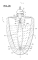
- FIG. 2B shows the same assembly 1 in the mounted position with a bottom 3 10 mm thick.
- the open ends 34 and 35 of the tubes 31 and 33 are in the same position relative to the inner surface of the bottom 3. They are also in position identical relative to the X axis of the container. Both containers can be emptied in much the same way.
- the product contained in the pump body 12 is distributed in the form of a cloud of fine droplets via the spray orifice 10.
- FIGS. 3A and 3B to which it is now made reference differs from the previous embodiment in that the structure forming dip tube 100 includes a single tube 31 folded back on itself in contact with the bottom 3.
- the two open ends 30 and 32 of the tube 31 are connected to the pump via a connection element 20 identical to the connection element of the previous embodiment.
- the portion of tube 31 located closest to the bottom 3 is crossed by a plurality of small orifices 101 allowing communication between the container and the dip tube, for the supply of the pump 7.
- Figure 3A mounts the assembly 1 in the mounted position with a bottom 3 of 5 mm thick.
- FIG. 3B shows the same assembly 1 in the mounted position with a bottom 3 10 mm thick.
- the loop formed by the structure 100 of FIG. 3A is significantly less axially crushed, and less open than that of the Figure 3B.
- the orifices 101 of the tube 31 are in identical position relative to the surface inside of the bottom 3. They are also in identical position relative to the X axis of the container. Both containers can be emptied in much the same way way.
Landscapes
- Containers And Packaging Bodies Having A Special Means To Remove Contents (AREA)
- Reciprocating Pumps (AREA)
- Vaporization, Distillation, Condensation, Sublimation, And Cold Traps (AREA)
Abstract
Description
- la figure 1 représente une vue éclatée d'un ensemble de conditionnement selon un premier mode de réalisation de l'invention ;
- les figures 2A et 2B sont des vues en coupe relatives au mode de réalisation de la figure 1 ;
- les figures 3A et 3B sont des vues en coupe relative à un second mode de réalisation de l'invention.
Claims (12)
- Ensemble (1) pour le conditionnement et la distribution d'un produit, notamment cosmétique comprenant :caractérisé en ce que la structure formant tube plongeur (100) est configurée sous forme d'une boucle comprimable axialement, s'étendant depuis le (ou les) orifice(s) (34, 35, 101) situé(s) au voisinage du fond (3) du récipient jusqu'à l'élément de distribution (7).i) un récipient (2) formant réservoir pour le produit et délimitant une ouverture (5) d'axe X ;ii) un élément de distribution (7), notamment une pompe à actionnement manuel, équipant ladite ouverture (5) ; etiii) une structure formant tube plongeur (100) pour l'alimentation en produit de l'élément de distribution, ladite structure comportant au moins un orifice d'entrée (34, 35, 101) situé au voisinage d'un fond (3) du récipient, et formant ressort axialement de sorte qu'une portion de ladite structure formant tube plongeur soit au contact dudit fond (3) quelle que soit la distance de l'élément de distribution au fond (3) à l'intérieur d'une plage de variation déterminée,
- Ensemble (1) selon la revendication 1 caractérisé en ce que l'orifice d'entrée (34, 35, 101) ou au moins un orifice d'entrée est à position sensiblement fixe relativement à l'axe X quelle que soit la distance de l'élément de distribution (7) au fond (3) à l'intérieur de ladite plage.
- Ensemble (1) selon la revendication 1 ou 2 caractérisé en ce que la boucle est constituée d'un tube unique (31) replié sur lui même au contact du fond (3), les première et seconde extrémités (30, 32) du tube étant connectées à l'élément de distribution (7), une portion du tube (31) située au voisinage du fond étant traversée par un ou plusieurs orifices (101).
- Ensemble (1) selon la revendication 1 ou 2 caractérisé en ce que la boucle est formée d'au moins deux tubes distincts (31, 33), une première extrémité ouverte (30, 32) de chaque tube étant connectée à l'élément de distribution (7), les seconde extrémités (34, 35) des tubes étant ouvertes et reliées entre elles par une première pièce de liaison (40) en contact avec le fond du récipient, et assurant la communication liquide entre les seconde extrémités ouvertes (34, 35) des tubes et le produit contenu dans le récipient (2).
- Ensemble (1) selon la revendication 4 caractérisé en ce que la première pièce de liaison (40) est réalisée en un matériau perméable au produit, notamment un fritté ou une mousse.
- Ensemble (1) selon la revendication 4 caractérisé en ce que la pièce de liaison (40) est ajourée de manière à permettre ladite communication liquide.
- Ensemble (1) selon l'une quelconque des revendications 4 à 6 caractérisé en ce que les première extrémités ouvertes (30, 32) desdits tubes sont connectées à l'élément de distribution (7) via une seconde pièce de liaison (20) identique à la première (40).
- Ensemble (1) selon l'une quelconque des revendications 1 à 7 caractérisé en ce que préalablement à son insertion à l'intérieur du récipient via ladite ouverture (5), la boucle est contrainte dans une configuration de largeur réduite selon un axe perpendiculaire à l'axe X, au moyen d'un lien (50) soluble dans le produit.
- Ensemble (1) selon l'une quelconque des revendications 1 à 8 caractérisé en ce que le récipient (2) est en verre.
- Ensemble (1) selon l'une quelconque des revendications 1 à 9 caractérisé en ce qu'une surface intérieure du fond (3) du récipient est concave, le sommet de la concavité étant tourné dans une direction opposée à l'ouverture (5).
- Ensemble (1) selon l'une quelconque des revendications qui précèdent caractérisé en ce que l'élément de distribution (7) est constitué d'une pompe montée sur le récipient, notamment par encliquetage, vissage ou sertissage.
- Utilisation d'un ensemble (1) selon l'une quelconque des revendications qui précèdent pour le conditionnement et la distribution d'un produit cosmétique, notamment d'un parfum.
Applications Claiming Priority (2)
| Application Number | Priority Date | Filing Date | Title |
|---|---|---|---|
| FR0206557 | 2002-05-29 | ||
| FR0206557A FR2840290B1 (fr) | 2002-05-29 | 2002-05-29 | Ensemble de conditionnement et de distribution du type a tube plongeur |
Publications (2)
| Publication Number | Publication Date |
|---|---|
| EP1367007A1 true EP1367007A1 (fr) | 2003-12-03 |
| EP1367007B1 EP1367007B1 (fr) | 2005-05-11 |
Family
ID=29415141
Family Applications (1)
| Application Number | Title | Priority Date | Filing Date |
|---|---|---|---|
| EP03291214A Expired - Lifetime EP1367007B1 (fr) | 2002-05-29 | 2003-05-22 | Ensemble de conditionnement et de distribution du type à tube plongeur |
Country Status (5)
| Country | Link |
|---|---|
| EP (1) | EP1367007B1 (fr) |
| AT (1) | ATE295318T1 (fr) |
| DE (1) | DE60300632T2 (fr) |
| ES (1) | ES2242148T3 (fr) |
| FR (1) | FR2840290B1 (fr) |
Cited By (2)
| Publication number | Priority date | Publication date | Assignee | Title |
|---|---|---|---|---|
| WO2012147079A1 (fr) * | 2011-04-28 | 2012-11-01 | Zafrir Efi | Connecteur universel destiné à des flacons à bouchon gicleur et flacons à bouchon gicleur contenant celui-ci |
| CN105249660A (zh) * | 2015-10-26 | 2016-01-20 | 吉林大学 | 一种仿碰碰香功能的车载香水瓶 |
Citations (3)
| Publication number | Priority date | Publication date | Assignee | Title |
|---|---|---|---|---|
| US2950031A (en) * | 1957-10-23 | 1960-08-23 | Precision Valve Corp | Liquid stream dispensing pressure package for high viscosity liquids |
| US3409184A (en) * | 1966-12-15 | 1968-11-05 | Owens Illinois Inc | Liquid dispensing device |
| US6027041A (en) * | 1992-11-10 | 2000-02-22 | Evnx Technologies, Inc. | Sprayer with swiveling spray head |
Family Cites Families (1)
| Publication number | Priority date | Publication date | Assignee | Title |
|---|---|---|---|---|
| FR2817845B1 (fr) * | 2000-12-08 | 2003-03-21 | Valois Sa | Distributeur de produit fluide |
-
2002
- 2002-05-29 FR FR0206557A patent/FR2840290B1/fr not_active Expired - Fee Related
-
2003
- 2003-05-22 ES ES03291214T patent/ES2242148T3/es not_active Expired - Lifetime
- 2003-05-22 AT AT03291214T patent/ATE295318T1/de not_active IP Right Cessation
- 2003-05-22 DE DE60300632T patent/DE60300632T2/de not_active Expired - Lifetime
- 2003-05-22 EP EP03291214A patent/EP1367007B1/fr not_active Expired - Lifetime
Patent Citations (3)
| Publication number | Priority date | Publication date | Assignee | Title |
|---|---|---|---|---|
| US2950031A (en) * | 1957-10-23 | 1960-08-23 | Precision Valve Corp | Liquid stream dispensing pressure package for high viscosity liquids |
| US3409184A (en) * | 1966-12-15 | 1968-11-05 | Owens Illinois Inc | Liquid dispensing device |
| US6027041A (en) * | 1992-11-10 | 2000-02-22 | Evnx Technologies, Inc. | Sprayer with swiveling spray head |
Cited By (2)
| Publication number | Priority date | Publication date | Assignee | Title |
|---|---|---|---|---|
| WO2012147079A1 (fr) * | 2011-04-28 | 2012-11-01 | Zafrir Efi | Connecteur universel destiné à des flacons à bouchon gicleur et flacons à bouchon gicleur contenant celui-ci |
| CN105249660A (zh) * | 2015-10-26 | 2016-01-20 | 吉林大学 | 一种仿碰碰香功能的车载香水瓶 |
Also Published As
| Publication number | Publication date |
|---|---|
| FR2840290A1 (fr) | 2003-12-05 |
| EP1367007B1 (fr) | 2005-05-11 |
| DE60300632D1 (de) | 2005-06-16 |
| ES2242148T3 (es) | 2005-11-01 |
| DE60300632T2 (de) | 2006-05-04 |
| FR2840290B1 (fr) | 2004-07-30 |
| ATE295318T1 (de) | 2005-05-15 |
Similar Documents
| Publication | Publication Date | Title |
|---|---|---|
| EP0899213B1 (fr) | Ensemble de conditionnement d'un produit liquide ou semi liquide du type à pompe | |
| CA2264256C (fr) | Tete pour la distribution et l'application d'un produit, notamment capillaire, et ensemble de conditionnement equipe d'une telle tete | |
| EP0486355B1 (fr) | Distributeur de produit, liquide à pâteux, et embase pour un tel distributeur | |
| FR2804665A1 (fr) | Aerosol a poche a etancheite amelioree | |
| EP1136136A2 (fr) | Ensemble de conditionnement et de distribution, et utilisation d'un tel ensemble pour le conditionnement d'un produit cosmétique, pharmaceutique ou dermopharmaceutique | |
| EP0905052B1 (fr) | Ensemble de conditionnement et de distribution d'un produit liquide ou semi liquide | |
| EP1193186A2 (fr) | Dispositif pour la fixation réversible d'un récipient sur un support et récipient équipé d'un tel dispositif. | |
| EP0626321B1 (fr) | Dispositif de distribution de liquide sans tube-plongeur | |
| EP0780324A1 (fr) | Distributeur de liquide comprenant un bouton-poussoir | |
| EP0613836A1 (fr) | Distributeur de mousse sous pression | |
| EP0385896B1 (fr) | Corps de distributeur, distributeur comportant un tel corps et dôme correspondant | |
| EP1172151A1 (fr) | Dispositif pour le conditionnement et la distribution dosée d'un produit liquide | |
| EP0850851B1 (fr) | Valve pour la distribution de fluides sous pression | |
| EP0995697B1 (fr) | Distributeur aérosol comportant un réservoir sphérique en matière plastique | |
| FR2715133A1 (fr) | Récipient à paroi souple déformable, du type flacon, poche ou tube, et procédé de fabrication d'un tel récipient. | |
| EP1367007B1 (fr) | Ensemble de conditionnement et de distribution du type à tube plongeur | |
| FR2734242A1 (fr) | Ensemble de distribution pour un produit liquide ou pulverulent, et procede de fabrication de cet ensemble | |
| FR2781210A1 (fr) | Distributeur de produits cremeux sous pression muni d'un piston etanche | |
| EP1363843B1 (fr) | Distributeur de produit fluide a poche souple et procede de fabrication d'une telle poche souple | |
| FR3047234A1 (fr) | Flacon pressurise en matiere plastique | |
| CA2151193C (fr) | Distributeur de liquide comprenant une valve de distribution et un bouton-poussoir | |
| EP3953271A1 (fr) | Dispositif porte valve pour recharge a poche, recharge a poche et boitier distributeur rechargeable le comprenant | |
| FR2700483A1 (fr) | Dispositif de pulvérisation, en particulier aérosol. | |
| FR2828480A1 (fr) | Dispositif de distribution d'un produit sans tube plongeur | |
| EP1153849A2 (fr) | Récipient aérosol à double enveloppe et son procédé de fabrication |
Legal Events
| Date | Code | Title | Description |
|---|---|---|---|
| PUAI | Public reference made under article 153(3) epc to a published international application that has entered the european phase |
Free format text: ORIGINAL CODE: 0009012 |
|
| AK | Designated contracting states |
Kind code of ref document: A1 Designated state(s): AT BE BG CH CY CZ DE DK EE ES FI FR GB GR HU IE IT LI LU MC NL PT RO SE SI SK TR |
|
| AX | Request for extension of the european patent |
Extension state: AL LT LV MK |
|
| 17P | Request for examination filed |
Effective date: 20040603 |
|
| AKX | Designation fees paid |
Designated state(s): AT BE BG CH CY CZ DE DK EE ES FI FR GB GR HU IE IT LI LU MC NL PT RO SE SI SK TR |
|
| GRAP | Despatch of communication of intention to grant a patent |
Free format text: ORIGINAL CODE: EPIDOSNIGR1 |
|
| GRAS | Grant fee paid |
Free format text: ORIGINAL CODE: EPIDOSNIGR3 |
|
| GRAA | (expected) grant |
Free format text: ORIGINAL CODE: 0009210 |
|
| AK | Designated contracting states |
Kind code of ref document: B1 Designated state(s): AT BE BG CH CY CZ DE DK EE ES FI FR GB GR HU IE IT LI LU MC NL PT RO SE SI SK TR |
|
| PG25 | Lapsed in a contracting state [announced via postgrant information from national office to epo] |
Ref country code: SK Free format text: LAPSE BECAUSE OF FAILURE TO SUBMIT A TRANSLATION OF THE DESCRIPTION OR TO PAY THE FEE WITHIN THE PRESCRIBED TIME-LIMIT Effective date: 20050511 Ref country code: TR Free format text: LAPSE BECAUSE OF FAILURE TO SUBMIT A TRANSLATION OF THE DESCRIPTION OR TO PAY THE FEE WITHIN THE PRESCRIBED TIME-LIMIT Effective date: 20050511 Ref country code: CZ Free format text: LAPSE BECAUSE OF FAILURE TO SUBMIT A TRANSLATION OF THE DESCRIPTION OR TO PAY THE FEE WITHIN THE PRESCRIBED TIME-LIMIT Effective date: 20050511 Ref country code: FI Free format text: LAPSE BECAUSE OF FAILURE TO SUBMIT A TRANSLATION OF THE DESCRIPTION OR TO PAY THE FEE WITHIN THE PRESCRIBED TIME-LIMIT Effective date: 20050511 Ref country code: EE Free format text: LAPSE BECAUSE OF FAILURE TO SUBMIT A TRANSLATION OF THE DESCRIPTION OR TO PAY THE FEE WITHIN THE PRESCRIBED TIME-LIMIT Effective date: 20050511 Ref country code: RO Free format text: LAPSE BECAUSE OF FAILURE TO SUBMIT A TRANSLATION OF THE DESCRIPTION OR TO PAY THE FEE WITHIN THE PRESCRIBED TIME-LIMIT Effective date: 20050511 Ref country code: NL Free format text: LAPSE BECAUSE OF FAILURE TO SUBMIT A TRANSLATION OF THE DESCRIPTION OR TO PAY THE FEE WITHIN THE PRESCRIBED TIME-LIMIT Effective date: 20050511 Ref country code: SI Free format text: LAPSE BECAUSE OF FAILURE TO SUBMIT A TRANSLATION OF THE DESCRIPTION OR TO PAY THE FEE WITHIN THE PRESCRIBED TIME-LIMIT Effective date: 20050511 Ref country code: IE Free format text: LAPSE BECAUSE OF FAILURE TO SUBMIT A TRANSLATION OF THE DESCRIPTION OR TO PAY THE FEE WITHIN THE PRESCRIBED TIME-LIMIT Effective date: 20050511 Ref country code: AT Free format text: LAPSE BECAUSE OF FAILURE TO SUBMIT A TRANSLATION OF THE DESCRIPTION OR TO PAY THE FEE WITHIN THE PRESCRIBED TIME-LIMIT Effective date: 20050511 |
|
| REG | Reference to a national code |
Ref country code: GB Ref legal event code: FG4D Free format text: NOT ENGLISH |
|
| REG | Reference to a national code |
Ref country code: CH Ref legal event code: EP |
|
| PG25 | Lapsed in a contracting state [announced via postgrant information from national office to epo] |
Ref country code: CY Free format text: LAPSE BECAUSE OF FAILURE TO SUBMIT A TRANSLATION OF THE DESCRIPTION OR TO PAY THE FEE WITHIN THE PRESCRIBED TIME-LIMIT Effective date: 20050522 Ref country code: LU Free format text: LAPSE BECAUSE OF NON-PAYMENT OF DUE FEES Effective date: 20050522 |
|
| PG25 | Lapsed in a contracting state [announced via postgrant information from national office to epo] |
Ref country code: MC Free format text: LAPSE BECAUSE OF NON-PAYMENT OF DUE FEES Effective date: 20050531 Ref country code: BE Free format text: LAPSE BECAUSE OF NON-PAYMENT OF DUE FEES Effective date: 20050531 |
|
| REG | Reference to a national code |
Ref country code: IE Ref legal event code: FG4D Free format text: LANGUAGE OF EP DOCUMENT: FRENCH |
|
| REF | Corresponds to: |
Ref document number: 60300632 Country of ref document: DE Date of ref document: 20050616 Kind code of ref document: P |
|
| PG25 | Lapsed in a contracting state [announced via postgrant information from national office to epo] |
Ref country code: DK Free format text: LAPSE BECAUSE OF FAILURE TO SUBMIT A TRANSLATION OF THE DESCRIPTION OR TO PAY THE FEE WITHIN THE PRESCRIBED TIME-LIMIT Effective date: 20050811 Ref country code: BG Free format text: LAPSE BECAUSE OF FAILURE TO SUBMIT A TRANSLATION OF THE DESCRIPTION OR TO PAY THE FEE WITHIN THE PRESCRIBED TIME-LIMIT Effective date: 20050811 Ref country code: SE Free format text: LAPSE BECAUSE OF FAILURE TO SUBMIT A TRANSLATION OF THE DESCRIPTION OR TO PAY THE FEE WITHIN THE PRESCRIBED TIME-LIMIT Effective date: 20050811 Ref country code: GR Free format text: LAPSE BECAUSE OF FAILURE TO SUBMIT A TRANSLATION OF THE DESCRIPTION OR TO PAY THE FEE WITHIN THE PRESCRIBED TIME-LIMIT Effective date: 20050811 |
|
| GBT | Gb: translation of ep patent filed (gb section 77(6)(a)/1977) |
Effective date: 20050721 |
|
| PG25 | Lapsed in a contracting state [announced via postgrant information from national office to epo] |
Ref country code: PT Free format text: LAPSE BECAUSE OF FAILURE TO SUBMIT A TRANSLATION OF THE DESCRIPTION OR TO PAY THE FEE WITHIN THE PRESCRIBED TIME-LIMIT Effective date: 20051019 |
|
| NLV1 | Nl: lapsed or annulled due to failure to fulfill the requirements of art. 29p and 29m of the patents act | ||
| REG | Reference to a national code |
Ref country code: ES Ref legal event code: FG2A Ref document number: 2242148 Country of ref document: ES Kind code of ref document: T3 |
|
| PG25 | Lapsed in a contracting state [announced via postgrant information from national office to epo] |
Ref country code: HU Free format text: LAPSE BECAUSE OF FAILURE TO SUBMIT A TRANSLATION OF THE DESCRIPTION OR TO PAY THE FEE WITHIN THE PRESCRIBED TIME-LIMIT Effective date: 20051112 |
|
| BERE | Be: lapsed |
Owner name: L'OREAL Effective date: 20050531 |
|
| REG | Reference to a national code |
Ref country code: IE Ref legal event code: FD4D |
|
| PLBE | No opposition filed within time limit |
Free format text: ORIGINAL CODE: 0009261 |
|
| STAA | Information on the status of an ep patent application or granted ep patent |
Free format text: STATUS: NO OPPOSITION FILED WITHIN TIME LIMIT |
|
| 26N | No opposition filed |
Effective date: 20060214 |
|
| BERE | Be: lapsed |
Owner name: L'OREAL Effective date: 20050531 |
|
| REG | Reference to a national code |
Ref country code: CH Ref legal event code: PL |
|
| PG25 | Lapsed in a contracting state [announced via postgrant information from national office to epo] |
Ref country code: CH Free format text: LAPSE BECAUSE OF NON-PAYMENT OF DUE FEES Effective date: 20070531 Ref country code: LI Free format text: LAPSE BECAUSE OF NON-PAYMENT OF DUE FEES Effective date: 20070531 |
|
| PGFP | Annual fee paid to national office [announced via postgrant information from national office to epo] |
Ref country code: GB Payment date: 20100329 Year of fee payment: 8 |
|
| PGFP | Annual fee paid to national office [announced via postgrant information from national office to epo] |
Ref country code: ES Payment date: 20100611 Year of fee payment: 8 Ref country code: FR Payment date: 20100525 Year of fee payment: 8 |
|
| PGFP | Annual fee paid to national office [announced via postgrant information from national office to epo] |
Ref country code: DE Payment date: 20100519 Year of fee payment: 8 Ref country code: IT Payment date: 20100522 Year of fee payment: 8 |
|
| GBPC | Gb: european patent ceased through non-payment of renewal fee |
Effective date: 20110522 |
|
| REG | Reference to a national code |
Ref country code: FR Ref legal event code: ST Effective date: 20120131 |
|
| PG25 | Lapsed in a contracting state [announced via postgrant information from national office to epo] |
Ref country code: IT Free format text: LAPSE BECAUSE OF NON-PAYMENT OF DUE FEES Effective date: 20110522 |
|
| REG | Reference to a national code |
Ref country code: DE Ref legal event code: R119 Ref document number: 60300632 Country of ref document: DE Effective date: 20111201 |
|
| PG25 | Lapsed in a contracting state [announced via postgrant information from national office to epo] |
Ref country code: FR Free format text: LAPSE BECAUSE OF NON-PAYMENT OF DUE FEES Effective date: 20110531 |
|
| PG25 | Lapsed in a contracting state [announced via postgrant information from national office to epo] |
Ref country code: GB Free format text: LAPSE BECAUSE OF NON-PAYMENT OF DUE FEES Effective date: 20110522 |
|
| REG | Reference to a national code |
Ref country code: ES Ref legal event code: FD2A Effective date: 20130606 |
|
| PG25 | Lapsed in a contracting state [announced via postgrant information from national office to epo] |
Ref country code: DE Free format text: LAPSE BECAUSE OF NON-PAYMENT OF DUE FEES Effective date: 20111201 |
|
| PG25 | Lapsed in a contracting state [announced via postgrant information from national office to epo] |
Ref country code: ES Free format text: LAPSE BECAUSE OF NON-PAYMENT OF DUE FEES Effective date: 20110523 |