EP1366922A2 - Power transmission arrangement - Google Patents
Power transmission arrangement Download PDFInfo
- Publication number
- EP1366922A2 EP1366922A2 EP03253179A EP03253179A EP1366922A2 EP 1366922 A2 EP1366922 A2 EP 1366922A2 EP 03253179 A EP03253179 A EP 03253179A EP 03253179 A EP03253179 A EP 03253179A EP 1366922 A2 EP1366922 A2 EP 1366922A2
- Authority
- EP
- European Patent Office
- Prior art keywords
- gear
- assembly
- power transmission
- transmission arrangement
- plate
- Prior art date
- Legal status (The legal status is an assumption and is not a legal conclusion. Google has not performed a legal analysis and makes no representation as to the accuracy of the status listed.)
- Granted
Links
Images




Classifications
-
- B—PERFORMING OPERATIONS; TRANSPORTING
- B41—PRINTING; LINING MACHINES; TYPEWRITERS; STAMPS
- B41J—TYPEWRITERS; SELECTIVE PRINTING MECHANISMS, i.e. MECHANISMS PRINTING OTHERWISE THAN FROM A FORME; CORRECTION OF TYPOGRAPHICAL ERRORS
- B41J23/00—Power drives for actions or mechanisms
- B41J23/02—Mechanical power drives
- B41J23/025—Mechanical power drives using a single or common power source for two or more functions
-
- Y—GENERAL TAGGING OF NEW TECHNOLOGICAL DEVELOPMENTS; GENERAL TAGGING OF CROSS-SECTIONAL TECHNOLOGIES SPANNING OVER SEVERAL SECTIONS OF THE IPC; TECHNICAL SUBJECTS COVERED BY FORMER USPC CROSS-REFERENCE ART COLLECTIONS [XRACs] AND DIGESTS
- Y10—TECHNICAL SUBJECTS COVERED BY FORMER USPC
- Y10T—TECHNICAL SUBJECTS COVERED BY FORMER US CLASSIFICATION
- Y10T74/00—Machine element or mechanism
- Y10T74/19—Gearing
- Y10T74/1956—Adjustable
-
- Y—GENERAL TAGGING OF NEW TECHNOLOGICAL DEVELOPMENTS; GENERAL TAGGING OF CROSS-SECTIONAL TECHNOLOGIES SPANNING OVER SEVERAL SECTIONS OF THE IPC; TECHNICAL SUBJECTS COVERED BY FORMER USPC CROSS-REFERENCE ART COLLECTIONS [XRACs] AND DIGESTS
- Y10—TECHNICAL SUBJECTS COVERED BY FORMER USPC
- Y10T—TECHNICAL SUBJECTS COVERED BY FORMER US CLASSIFICATION
- Y10T74/00—Machine element or mechanism
- Y10T74/19—Gearing
- Y10T74/1956—Adjustable
- Y10T74/19565—Relative movable axes
-
- Y—GENERAL TAGGING OF NEW TECHNOLOGICAL DEVELOPMENTS; GENERAL TAGGING OF CROSS-SECTIONAL TECHNOLOGIES SPANNING OVER SEVERAL SECTIONS OF THE IPC; TECHNICAL SUBJECTS COVERED BY FORMER USPC CROSS-REFERENCE ART COLLECTIONS [XRACs] AND DIGESTS
- Y10—TECHNICAL SUBJECTS COVERED BY FORMER USPC
- Y10T—TECHNICAL SUBJECTS COVERED BY FORMER US CLASSIFICATION
- Y10T74/00—Machine element or mechanism
- Y10T74/19—Gearing
- Y10T74/19614—Disconnecting means
Definitions
- An inkjet printing system may include a printhead and an ink supply which supplies liquid ink to the printhead.
- the printhead ejects ink drops through a plurality of orifices or nozzles and toward a print medium, such as a sheet of paper, so as to print onto the print medium.
- the orifices are arranged in one or more arrays such that properly sequenced ejection of ink from the orifices causes characters or other images to be printed upon the print medium as the printhead and the print medium are moved relative to each other.
- An inkjet printing system may include a print media transport assembly which moves and/or routes the print medium through a print media path, a carriage assembly which moves the printhead relative to the print medium, and a service station assembly which maintains functionality of the printhead.
- the print media transport assembly typically includes a paper pick-up assembly which brings the print medium into the printing system, a drive or feed roller assembly which advances the print medium through the printing system, and a paper path motor which operates the paper pick-up assembly and the feed roller assembly.
- the carriage assembly typically includes a carriage which carries the printhead and a carriage motor which operates the carriage.
- the service station assembly typically includes a service station motor which operates functions of the service station assembly.
- Operation of these types of inkjet printing systems therefore, involves the operation of three separate motors. More specifically, operation of the inkjet printing system involves the operation of a paper path motor, a carriage motor, and a service station motor. Unfortunately, the use of three motors adds to the size, complexity, and cost of these types of inkjet printing systems.
- a power transmission arrangement includes a shaft, a first gear mounted on the shaft, a plate supported by the shaft and rotatable between a first position and a second position, a second gear supported by the plate and engaged with the first gear, and a third gear supported by the plate and movable between a disengaged position and an engaged position with the second gear when the plate is rotated between the first position and the second position.
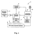
- Figure 1 illustrates one embodiment of an inkjet printing system 10 according to embodiments of the present invention.
- Inkjet printing system 10 includes an inkjet printhead assembly 12, an ink supply assembly 14, a carriage assembly 16, a print media transport assembly 18, a service station assembly 20, and an electronic controller 22.
- Inkjet printhead assembly 12 includes one or more printheads which eject drops of ink through a plurality of orifices or nozzles 13 and toward an embodiment of media, such as print medium 19, so as to print onto print medium 19.
- Print medium 19 is any type of suitable sheet material, such as paper, card stock, transparencies, Mylar, cloth, and the like.
- nozzles 13 are arranged in one or more columns or arrays such that properly sequenced ejection of ink from nozzles 13 causes characters, symbols, and/or other graphics or images to be printed upon print medium 19 as inkjet printhead assembly 12 and print medium 19 are moved relative to each other.
- Ink supply assembly 14 supplies ink to inkjet printhead assembly 12 and includes a reservoir 15 for storing ink. As such, ink flows from reservoir 15 to inkjet printhead assembly 12.
- inkjet printhead assembly 12 and ink supply assembly 14 are housed together in an inkjet cartridge or pen.
- ink supply assembly 14 is separate from inkjet printhead assembly 12 and supplies ink to inkjet printhead assembly 12 through an interface connection, such as a supply tube.
- reservoir 15 of ink supply assembly 14 may be removed, replaced, and/or refilled.
- Carriage assembly 16 positions inkjet printhead assembly 12 relative to print media transport assembly 18 and print media transport assembly 18 positions print medium 19 relative to inkjet printhead assembly 12.
- a print zone 17 is defined adjacent to nozzles 13 in an area between inkjet printhead assembly 12 and print medium 19.
- inkjet printhead assembly 12 is a scanning type printhead assembly. As such, carriage assembly 16 moves inkjet printhead assembly 12 relative to print media transport assembly 18 to scan print medium 19.
- Service station assembly 20 provides for spitting, wiping, capping, and/or priming of inkjet print assembly 12 in order to maintain a functionality of inkjet printhead assembly and, more specifically, nozzles 13.
- service station assembly 20 includes a rubber blade or wiper which is periodically passed over inkjet printhead assembly 12 to wipe and clean nozzles 13 of excess ink.
- service station assembly 20 includes a cap which covers inkjet printhead assembly 12 to protect nozzles 13 from drying out during periods of non-use.
- service station assembly 20 includes a spittoon into which inkjet printhead assembly 12 ejects ink to insure that reservoir 15 maintains an appropriate level of pressure and fluidity and that nozzles 13 do not clog or weep. Functions of service station assembly 20 include relative motion between service station assembly 20 and inkjet printhead assembly 12.
- Electronic controller 22 communicates with inkjet printhead assembly 12, carriage assembly 16, print media transport assembly 18, and service station assembly 20.
- Electronic controller 22 receives data 23 from a host system, such as a computer, and includes memory for temporarily storing data 23.
- data 23 is sent to inkjet printing system 10 along an electronic, infrared, optical or other information transfer path.
- Data 23 represents, for example, a document and/or file to be printed. As such, data 23 forms a print job for inkjet printing system 10 and includes one or more print job commands and/or command parameters.
- electronic controller 22 provides control of inkjet printhead assembly 12 including timing control for ejection of ink drops from nozzles 13.
- electronic controller 22 defines a pattern of ejected ink drops which form characters, symbols, and/or other graphics or images on print medium 19. Timing control and, therefore, the pattern of ejected ink drops, is determined by the print job commands and/or command parameters.
- inkjet printing system 10 includes a drive motor 24.
- Motor 24 is operatively coupled with print media transport assembly 18 and service station assembly 20.
- motor 24 operates, drives, or powers both print media transport assembly 18 and service station assembly 20.
- power from motor 24 is selectively transmitted to both print media transport assembly 18 and service station assembly 20, as described below.
- Motor 24, therefore, includes an output 25 which is selectively coupled with both print media transport assembly 18 and service station assembly 20.
- Figure 2 is a simplified schematic illustration of a portion of inkjet printing system 10.
- carriage assembly 16 includes a carriage rail 30 and a carriage 32.
- Carriage rail 30 is mounted in a housing (not shown) of inkjet printing system 10 and provides a guide for carriage 32.
- Carriage 32 carries inkjet printhead assembly 12 and is slidably mounted on carriage rail 30 for lateral movement, as indicated by bi-directional arrow 33. As such, carriage 32 moves inkjet printhead assembly 12 back and forth across print medium 19.
- print medium transport assembly 18 includes a drive shaft 40 and one or more rollers 42.
- Drive shaft 40 is mounted in a housing (not shown) of inkjet printing system 10 for rotational movement, as indicated by bi-directional arrow 41.
- Rollers 42 are mounted on drive shaft 40 to contact and route print medium 19 through a print media path of inkjet printing system 10. As such, rollers 42 advance print medium 19 relative to carriage 32 in a direction substantially perpendicular to the direction of motion of carriage 32.
- print media transport assembly 18 includes a paper pick-up assembly 44 and a feed roller assembly 46.
- Paper pick-up assembly 44 initially engages a top sheet of print medium 19 and routes print medium 19 to rollers 42.
- feed roller assembly 46 advances print medium 19 through the print media path of inkjet printing system 10. Motion is imparted to paper pick-up assembly 44 and feed roller assembly 46 via drive shaft 40.
- power transmission arrangement 50 includes a gear train 52 which transfers rotational power of motor 24 to drive shaft 40 of print media transport assembly 18 and a gear train 54 which transfers rotational power of motor 24 to paper pick-up assembly 44 and/or feed roller assembly 46.
- Gear train 52 therefore, imparts rotational motion of motor 24 to drive shaft 40 and rollers 42.
- Gear train 54 therefore, imparts rotational motion of drive shaft 40 to paper pick-up assembly 44 and/or feed roller assembly 46.
- service station assembly 20 includes a service station sled or pallet 60 and a frame or chassis 62.
- service station pallet 60 carries, for example, one or more wipers 64 which pass over inkjet printhead assembly 12 to clean and/or remove excess ink from a face of inkjet printhead assembly 12.
- service station pallet 60 carries at least one cap 66 which covers inkjet printhead assembly 12 when not in use to prevent inkjet printhead assembly 12 from drying out.
- Wiping and capping of inkjet printhead assembly 12 can utilize the motion of service station assembly 20 and, more specifically, motion of service station pallet 60 relative to inkjet printhead assembly 12.
- service station pallet 60 is mounted in chassis 62 for movement, as indicated by bi-directional arrow 61.
- movement of service station pallet 60 is in a direction substantially perpendicular to the direction of movement of carriage 32.
- service station pallet 60 provides for orthogonal and translational wiping of inkjet printhead assembly 12.
- power transmission arrangement 70 To transfer power of motor 24 to service station assembly 20, an embodiment of a power transmission arrangement, such as power transmission arrangement 70, is interposed between motor 24 and service station assembly 20.
- power transmission arrangement 70 includes an embodiment of a gear train, such as gear train 72, which transfers rotational power of motor 24 to service station pallet 60. Power from motor 24 is transferred to service station pallet 60 via gear train 72, as described in detail below.
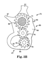
- Figures 3A and 3B illustrate one embodiment of power transmission arrangement 70. More specifically, Figure 3A illustrates power transmission arrangement 70 in a disengaged mode of operation with power from motor 24 being uncoupled from service station assembly 20 and Figure 3B illustrates power transmission arrangement 70 in an engaged mode of operation with power from motor 24 being coupled to service station assembly 20.
- power transmission arrangement 70 includes an embodiment of a shift plate, such as shift plate 80, an embodiment of a drive gear, such as drive gear 74, an embodiment of an idler gear, such as idler gear 76, and an embodiment of a pinion gear, such as pinion gear 78.
- drive gear 74, idler gear 76, and pinion gear 78 constitute one embodiment of gear train 72 ( Figure 2).
- Shift plate 80 is supported for rotation between a first position, as illustrated in Figure 3A, and a second position, as illustrated in Figure 3B.
- drive shaft 40 extends through and supports shift plate 80.
- shift plate 80 is supported by and rotatable relative to drive shaft 40.
- shift plate 80 is rotatable between the first position and the second position about an axis of drive shaft 40. Rotation of shift plate 80 between the first position and the second position moves pinion gear 78 between a disengaged position and an engaged position with idler gear 76, as described below.
- Drive gear 74 is mounted on drive shaft 40 for rotation with drive shaft 40. As such, drive gear 74 is rotatable relative to shift plate 80. In addition, idler gear 76 is supported by shift plate 80 and engaged with drive gear 74. Idler gear 76 is freely supported by shift plate 80 such that rotational motion of drive gear 74 is imparted to idler gear 76.
- pinion gear 78 is supported by shift plate 80 and moveable between a disengaged position, as illustrated in Figure 3A, and an engaged position, as illustrated in Figure 3B. More specifically, in the disengaged position, pinion gear 78 is disengaged from idler gear 76 such that rotational motion of drive gear 74 is not imparted to pinion gear 78 via idler gear 76. However, in the engaged position, pinion gear 78 is engaged with idler gear 76 such that rotational motion of drive gear 74 is imparted to pinion gear 78 via idler gear 76.
- shift plate 80 includes a cam feature 81 which moves pinion gear 78 between the disengaged position and the engaged position when shift plate 80 is rotated between the first position and the second position.
- cam feature 81 includes a first cam surface 82 and a second cam surface 83.
- First cam surface 82 and second cam surface 83 are arranged such that pinion gear 78 is supported by first cam surface 82 when in the disengaged position and second cam surface 83 when in the engaged position.
- pinion gear 78 follows first cam surface 82 and then second cam surface 83 so as to move between the disengaged position and the engaged position.
- pinion gear 78 engages idler gear 76 such that drive gear 74 drives pinion gear 78 via idler gear 76 when shift plate 80 is in the second position.
- shift plate 80 includes a body portion 84 and an arm portion 85 extending from body portion 84.
- drive gear 74 and idler gear 76 are supported by body portion 84 and cam feature 81, including first cam surface 82 and second cam surface 83, is formed on arm portion 85.
- inkjet printing system 10 includes a support plate 28 which supports shift plate 80 and, more specifically, drive shaft 40.
- shift plate 80 includes a stop 86 which interacts with support plate 28 to limit rotation of shift plate 80.
- Stop 86 includes, for example, an arm 87 ( Figures 3A and 3B) which protrudes from shift plate 80 and extends into an opening 29 of support plate 28 such that in the first position ( Figure 4A), stop 86 of shift plate 80 contacts support plate 28.
- shift plate 80 is biased to the first position.
- Shift plate 80 is biased, for example, by a spring 88 secured at one end to shift plate 80 and at another end to support plate 28.
- stop 86 limits rotation of shift plate 80 as induced by spring 88.
- spring 88 is secured to a hook 89 ( Figures 3A and 3B) protruding from shift plate 80.
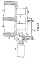
- movement of carriage assembly 16 actuates power transmission arrangement 70 to selectively couple motor 24 with service station assembly 20. More specifically, as illustrated in Figure 4B, movement of carriage 32 rotates shift plate 80 between the first position and the second position. For example, as carriage 32 traverses an end of carriage rail 30 in a direction toward service station assembly 20, carriage 32 contacts shift plate 80 and rotates shift plate 80 to the second position. As such, pinion gear 78 is moved by cam feature 81, including, more specifically, second cam surface 83, to the engaged position ( Figure 3B).
- shift plate 80 includes a cam or gathering feature 90 which interacts with carriage 32 to rotate shift plate 80 to the second position. Gathering feature 90 includes, for example, a tab 91 ( Figures 3A and 3B) which protrudes from shift plate 80 and fits into a slot or groove 34 in carriage 32. In one embodiment, tab 91 and/or groove 34 include angled surfaces which mate and cause shift plate 80 to rotate between the first position and the second position in response to lateral movement of carriage 32.
- pinion gear 78 includes a first gear wheel 781 and a second gear wheel 782.
- first gear wheel 781 selectively engages idler gear 76, as described above
- second gear wheel 782 engages corresponding teeth or gearing 68 of service station pallet 60. More specifically, when shift plate 80 is in the first position, as described above, first gear wheel 781 of pinion gear 78 is disengaged from idler gear 76. As such, power from motor 24, via drive shaft 40, is not imparted to first gear wheel 781 of pinion gear 78 and, therefore, service station pallet 60.
- first gear wheel 781 of pinion gear 78 is engaged with idler gear 76.
- power from motor 24, via drive shaft 40, drive gear 74, and idler gear 76 is imparted to first gear wheel 781 of pinion gear 78.
- rotational motion is imparted to second gear wheel 782 of pinion gear 78 and, therefore, gearing 68 of service station pallet 60.
- service station pallet 60 is selectively moved in the direction of bi-directional arrow 61 ( Figure 2) to service inkjet printhead assembly 12 as supported in carriage 32.
- carriage 32 carries two inkjet printhead assemblies 12 and service station pallet 60 carries two wipers 64 which pass over respective inkjet printhead assemblies 12.
- motor 24 By selectively coupling motor 24 with print media transport assembly 18 and service station assembly 20, motor 24 can operate functions of both print media transport assembly 18 and service station assembly 20.
- motor 24 can control multiple functions of inkjet print system 10, such as transporting print medium 19 and/or maintaining inkjet printhead assembly 12.
- inkjet printing system 10 may be made smaller or made to perform more functions for the same size, may be easier to manufacture, and/or may be less expensive to manufacture.
Landscapes
- Ink Jet (AREA)
- Handling Of Sheets (AREA)
- Rotary Presses (AREA)
- Character Spaces And Line Spaces In Printers (AREA)
- Gear Transmission (AREA)
Abstract
Description
Claims (17)
- A printing system (10), comprising:wherein the carriage assembly is adapted to actuate the power transmission arrangement to selectively couple the motor with the service station assembly.a media transport assembly (18) adapted to route media (19) through the printing system;a carriage assembly (16) adapted to hold a printhead (12) and traverse the media;a service station assembly (20) adapted to service the printhead;a motor (24) adapted to drive the media transport assembly and the service station assembly; anda power transmission arrangement (70) operatively coupling the motor with the service station assembly,
- The printing system of claim 1, wherein the power transmission arrangement includes:a drive shaft (40);a drive gear (74) mounted on the drive shaft;a shift plate (80) supported by the drive shaft and rotatable between a first position and a second position;an idler gear (76) supported by the shift plate and engaged with the drive gear; anda pinion gear (78) supported by the shift plate and movable between a disengaged position and an engaged position with the idler gear when the shift plate is rotated between the first position and the second position.
- The printing system of claim 2, wherein the carriage assembly is adapted to rotate the shift plate of the power transmission arrangement between the first position and the second position.
- The printing system of claim 1, wherein the carriage assembly is adapted to traverse the media in a first direction and rotate a portion of the power transmission arrangement in a second direction substantially perpendicular to the firstdirection to selectively couple the motor with the service station assembly.
- The printing system of claim 4, wherein the motor is adapted to move a portion of the service station assembly in the second direction.
- A method of operating a printing system (10) including a printhead (12), the method comprising:routing media (19) through the printing system via a media transport assembly (18);traversing the media with the printhead via a carriage assembly (16);servicing the printhead via a service station assembly (20); anddriving the media transport assembly and the service station assembly with a motor (24), including actuating a power transmission arrangement (70) by the carriage assembly to selectively couple the motor with the service station assembly.
- The method of claim 6, wherein the power transmission arrangement includes:a drive shaft (40);a drive gear (74) mounted on the drive shaft;a shift plate (80) supported by the drive shaft and rotatable between a first position and a second position;an idler gear (76) supported by the shift plate and engaged with the drive gear; anda pinion gear (78) supported by the shift plate and movable between a disengaged position and an engaged position with the idler gear when the shift plate is rotated between the first position and the second position.
- The method of claim 7, wherein actuating the power transmission arrangement includes rotating the shift plate of the power transmission arrangement between the first position and the second position with the carriage assembly.
- The method of claim 6, wherein traversing the media includes moving the printhead in a first direction via the carriage assembly and wherein actuating the power transmission arrangement includes rotating a portion of the power transmission arrangement in a second direction substantially perpendicular to the first direction via the carriage assembly.
- The method of claim 9, wherein driving the media transport assembly and the service station assembly includes moving a portion of the service station assembly in the second direction with the motor.
- A power transmission arrangement (70), comprising:a shaft (40);a first gear (74) mounted on the shaft;a plate (80) supported by the shaft and rotatable between a first position and a second position;a second gear (76) supported by the plate and engaged with the first gear; anda third gear (78) supported by the plate and movable between a disengaged position and an engaged position with the second gear when the plate is rotated between the first position and the second position.
- The power transmission arrangement of claim 11, wherein the first gear is adapted to drive the third gear via the second gear when the plate is in the second position.
- The power transmission arrangement of claim 11, wherein the plate is rotatable between the first position and the second position about an axis of the shaft.
- The power transmission arrangement of claim 11, wherein the plate includes a cam feature (81) adapted to move the third gear between the disengaged position and the engaged position when the plate is rotated between the first position and the second position.
- The power transmission arrangement of claim 14, wherein the cam feature includes a first cam surface (82) and a second cam surface (83), wherein the third gear is supported by the first cam surface when in the disengaged position and the second cam surface when in the engaged position.
- The power transmission arrangement of claim 11, further comprising:a spring (88) coupled to the plate, wherein the spring is adapted to bias the plate to the first position.
- The power transmission arrangement of claim 11, wherein the plate includes a stop (86) adapted to limit rotation of the plate and establish the first position thereof.
Applications Claiming Priority (2)
| Application Number | Priority Date | Filing Date | Title |
|---|---|---|---|
| US164119 | 2002-05-31 | ||
| US10/164,119 US6890055B2 (en) | 2002-05-31 | 2002-05-31 | Power transmission arrangement |
Publications (3)
| Publication Number | Publication Date |
|---|---|
| EP1366922A2 true EP1366922A2 (en) | 2003-12-03 |
| EP1366922A3 EP1366922A3 (en) | 2004-03-03 |
| EP1366922B1 EP1366922B1 (en) | 2006-10-18 |
Family
ID=29419763
Family Applications (1)
| Application Number | Title | Priority Date | Filing Date |
|---|---|---|---|
| EP03253179A Expired - Lifetime EP1366922B1 (en) | 2002-05-31 | 2003-05-21 | Power transmission arrangement |
Country Status (4)
| Country | Link |
|---|---|
| US (2) | US6890055B2 (en) |
| EP (1) | EP1366922B1 (en) |
| JP (1) | JP2004001474A (en) |
| DE (1) | DE60309099T2 (en) |
Families Citing this family (16)
| Publication number | Priority date | Publication date | Assignee | Title |
|---|---|---|---|---|
| US7753471B2 (en) * | 2004-02-17 | 2010-07-13 | Hewlett-Packard Development Company, L.P. | Printing mechanism and method |
| US7464922B2 (en) * | 2004-08-31 | 2008-12-16 | Brother Kogyo Kabushiki Kaisha | Image-recording apparatus, and recording-medium supply device |
| KR100586253B1 (en) * | 2004-09-24 | 2006-06-07 | 로얄소브린 주식회사 | How to use coin separator and coin separator |
| FR2884463B1 (en) * | 2005-04-13 | 2007-06-29 | Faurecia Sieges Automobile | ADJUSTING MECHANISM AND VEHICLE SEAT COMPRISING SUCH A MECHANISM |
| JP2009536299A (en) * | 2006-05-09 | 2009-10-08 | パルド, サンチャゴ カネド | Rotation control system |
| US7828283B2 (en) * | 2007-07-19 | 2010-11-09 | Hewlett-Packard Development Company, L.P. | Sheet feed method and apparatus including pivotally mounted pick arm |
| US7988255B2 (en) * | 2008-01-04 | 2011-08-02 | Eastman Kodak Company | Full function maintenance station |
| US8104885B2 (en) * | 2008-01-04 | 2012-01-31 | Eastman Kodak Company | Selector for engagement of printer functions |
| US20100080626A1 (en) * | 2008-09-26 | 2010-04-01 | Foster Thomas J | Multicolor image uniformity by reducing sensitivity to gear train drive non-uniformity |
| US8302957B2 (en) * | 2009-02-25 | 2012-11-06 | Eastman Kodak Company | Motor inside pick-up roller |
| US8851830B2 (en) * | 2009-10-08 | 2014-10-07 | Rolls-Royce Corporation | Harmonization of multiple gear train configurations |
| JP2011232386A (en) * | 2010-04-23 | 2011-11-17 | Fuji Xerox Co Ltd | Retention mechanism of distance between shafts of gears, image formation apparatus and assembly |
| JP5740855B2 (en) * | 2010-07-02 | 2015-07-01 | 株式会社リコー | Image forming apparatus |
| US20130025391A1 (en) * | 2011-07-27 | 2013-01-31 | Daniel James Magnusson | Gear Backlash Compensation In A Printing Device |
| JP6060495B2 (en) * | 2012-02-27 | 2017-01-18 | セイコーエプソン株式会社 | Liquid ejector |
| WO2015053786A1 (en) * | 2013-10-11 | 2015-04-16 | Hewlett-Packard Development Company, L.P. | Printer gear train assembly |
Family Cites Families (35)
| Publication number | Priority date | Publication date | Assignee | Title |
|---|---|---|---|---|
| US571224A (en) * | 1896-11-10 | Robert galloway | ||
| US638194A (en) * | 1899-04-15 | 1899-11-28 | Tripp Bros | Reel for angling, &c. |
| US2681035A (en) * | 1951-07-25 | 1954-06-15 | Cocker Machine & Foundry Compa | Automatic control mechanism in strand marking machine |
| US2856787A (en) * | 1955-05-24 | 1958-10-21 | Kienzle Apparate Gmbh | Variable transmission gearing for use in taximeters |
| US2854855A (en) * | 1956-03-20 | 1958-10-07 | Altofer Bros Company | Control timer |
| US3943786A (en) * | 1974-05-02 | 1976-03-16 | Polaroid Corporation | Photographic film processing apparatus having disengagement means |
| JPS588060B2 (en) * | 1974-11-06 | 1983-02-14 | 株式会社リコー | Jidohanten Oyobi Teishikikou |
| US4133216A (en) * | 1977-12-16 | 1979-01-09 | Vamco Machine & Tool, Inc. | Gear support assembly |
| US4347009A (en) * | 1981-06-16 | 1982-08-31 | International Business Machines Corporation | Operator interchangeable gear driven platen and platen drive mechanism for typewriters and printers |
| JPS61155149A (en) * | 1984-12-27 | 1986-07-14 | Sharp Corp | Intermittent transmission device for drive force |
| JPS6215141U (en) * | 1985-07-12 | 1987-01-29 | ||
| US5417370A (en) * | 1986-11-18 | 1995-05-23 | Kah, Jr.; Carl L. C. | Transmission device having an adjustable oscillating output |
| US5020386A (en) * | 1989-11-27 | 1991-06-04 | Allied-Signal Inc. | Reversing mechanism for a motor drive |
| JP2566184B2 (en) * | 1992-05-28 | 1996-12-25 | 大陽工業株式会社 | Vehicle toy drive |
| JPH0683119A (en) | 1992-08-28 | 1994-03-25 | Ricoh Co Ltd | Driving transmitting mechanism |
| JP3530621B2 (en) | 1994-04-08 | 2004-05-24 | キヤノン株式会社 | Recovery device and ink jet recording apparatus provided with the recovery device |
| US5559538A (en) | 1994-08-12 | 1996-09-24 | Hewlett-Packard Company | Positioning of service station and paper pick pressure plate using single motor |
| JPH08135680A (en) | 1994-11-14 | 1996-05-31 | Technol Seven Co Ltd | Clutch mechanism by gear |
| JPH08174958A (en) * | 1994-12-26 | 1996-07-09 | Brother Ind Ltd | Inkjet print recorder |
| US5886714A (en) | 1995-03-06 | 1999-03-23 | Hewlett-Packard Company | Actuation mechanism for translational wiping of a stationary inkjet printhead |
| US5980018A (en) | 1995-07-31 | 1999-11-09 | Hewlett-Packard Company | Translational service station system for inkjet printheads |
| US6328412B1 (en) | 1995-07-31 | 2001-12-11 | Hewlett-Packard Company | Integrated translational service station for inkjet printheads |
| JPH0971333A (en) * | 1995-09-06 | 1997-03-18 | Brother Ind Ltd | Paper feeder |
| JPH09109380A (en) * | 1995-10-20 | 1997-04-28 | Brother Ind Ltd | Inkjet printer |
| KR100193712B1 (en) | 1996-01-09 | 1999-06-15 | 윤종용 | Service station apparatus of head for ink jet printer |
| JPH09242843A (en) | 1996-03-13 | 1997-09-16 | Canon Inc | Drive transmission switching mechanism |
| US5788330A (en) * | 1997-03-27 | 1998-08-04 | Fisher Dynamics Corporation | Seat hinge mechanism with easy entry memory feature |
| US6070482A (en) | 1997-04-21 | 2000-06-06 | Nidec Copal Corporation | Gear module |
| US6000779A (en) | 1997-08-29 | 1999-12-14 | Hewlett-Packard Company | Triple-cartridge inkjet service station |
| US6113232A (en) | 1997-12-19 | 2000-09-05 | Hewlett-Packard Company | Stationary pen printer |
| US6367994B2 (en) | 1999-01-11 | 2002-04-09 | Seiko Epson Corporation | Power transmission switching device, rocking lever locking device in power transmission switching device and power transmission switching device-applied recording apparatus |
| US6547236B1 (en) * | 2000-01-05 | 2003-04-15 | Hewlett-Packard Company | Pick-up mechanism and a method for performing a pick-up cycle in a reproduction machine |
| US6561618B1 (en) * | 2000-11-17 | 2003-05-13 | Agilent Technologies, Inc. | Service station for printers having firing nozzles perpendicular to direction of carriage motion |
| US6666446B2 (en) * | 2001-06-13 | 2003-12-23 | Hewlett-Packard Development Company, L.P. | Replaceable roller bogie for document feeding apparatus |
| US6846060B2 (en) * | 2003-04-22 | 2005-01-25 | Hewlett-Packard Development Company | Printhead servicing mechanism and method |
-
2002
- 2002-05-31 US US10/164,119 patent/US6890055B2/en not_active Expired - Lifetime
-
2003
- 2003-04-10 JP JP2003106460A patent/JP2004001474A/en active Pending
- 2003-05-21 DE DE60309099T patent/DE60309099T2/en not_active Expired - Lifetime
- 2003-05-21 EP EP03253179A patent/EP1366922B1/en not_active Expired - Lifetime
- 2003-09-09 US US10/657,973 patent/US7225697B2/en not_active Expired - Lifetime
Also Published As
| Publication number | Publication date |
|---|---|
| EP1366922B1 (en) | 2006-10-18 |
| DE60309099D1 (en) | 2006-11-30 |
| US20040046826A1 (en) | 2004-03-11 |
| EP1366922A3 (en) | 2004-03-03 |
| US6890055B2 (en) | 2005-05-10 |
| JP2004001474A (en) | 2004-01-08 |
| US7225697B2 (en) | 2007-06-05 |
| US20030222937A1 (en) | 2003-12-04 |
| DE60309099T2 (en) | 2007-05-16 |
Similar Documents
| Publication | Publication Date | Title |
|---|---|---|
| US6890055B2 (en) | Power transmission arrangement | |
| US6659586B2 (en) | System and method for servicing non-scanning printhead | |
| JP5004533B2 (en) | Inkjet image forming apparatus and nozzle part maintenance method | |
| EP0398348B1 (en) | An ink jet recording apparatus | |
| KR100526492B1 (en) | Apparatus and method for cleaning ink jet printer | |
| US6585351B2 (en) | Angular wiping system for inkjet printheads | |
| US6533387B2 (en) | Inkjet printing system using single motor for print media advance and carriage motion | |
| US6749298B1 (en) | Power transmission arrangement | |
| US5963229A (en) | Ink jet recording apparatus having ink absorbing member for absorbing ink from an ink wiping member | |
| US6761428B2 (en) | Independent wiping of printhead | |
| US6959978B2 (en) | Sensor cleaning apparatus for ink-jet printer | |
| US6572292B2 (en) | Apparatus and method for transporting print media through a printzone of a printing device | |
| US6755504B2 (en) | Independent wiping of printhead | |
| US20060132520A1 (en) | Multiple-function inkjet printing system with single motor for carriage and scan head motion | |
| US6755505B2 (en) | Carriage dam for inkjet printer | |
| EP3274180A1 (en) | Printer gear arrangement | |
| US9261133B2 (en) | Media transport assembly shaft | |
| JP2005161857A (en) | Inkjet printer | |
| JP2004042483A (en) | Inkjet recording device | |
| JP2004160945A (en) | Inkjet recording device | |
| JPH10258516A (en) | Ink-jet recording apparatus | |
| JPH11254708A (en) | Ink jet recording device | |
| JP2006326982A (en) | Inkjet recorder | |
| JP2003246073A (en) | Cleaning method for inkjet printer |
Legal Events
| Date | Code | Title | Description |
|---|---|---|---|
| PUAI | Public reference made under article 153(3) epc to a published international application that has entered the european phase |
Free format text: ORIGINAL CODE: 0009012 |
|
| AK | Designated contracting states |
Kind code of ref document: A2 Designated state(s): AT BE BG CH CY CZ DE DK EE ES FI FR GB GR HU IE IT LI LU MC NL PT RO SE SI SK TR |
|
| AX | Request for extension of the european patent |
Extension state: AL LT LV MK |
|
| PUAL | Search report despatched |
Free format text: ORIGINAL CODE: 0009013 |
|
| AK | Designated contracting states |
Kind code of ref document: A3 Designated state(s): AT BE BG CH CY CZ DE DK EE ES FI FR GB GR HU IE IT LI LU MC NL PT RO SE SI SK TR |
|
| AX | Request for extension of the european patent |
Extension state: AL LT LV MK |
|
| RIC1 | Information provided on ipc code assigned before grant |
Ipc: 7F 16H 3/34 B Ipc: 7B 41J 23/02 A Ipc: 7F 16H 1/06 B |
|
| 17P | Request for examination filed |
Effective date: 20040423 |
|
| 17Q | First examination report despatched |
Effective date: 20040708 |
|
| AKX | Designation fees paid |
Designated state(s): DE FR GB |
|
| GRAP | Despatch of communication of intention to grant a patent |
Free format text: ORIGINAL CODE: EPIDOSNIGR1 |
|
| GRAS | Grant fee paid |
Free format text: ORIGINAL CODE: EPIDOSNIGR3 |
|
| GRAA | (expected) grant |
Free format text: ORIGINAL CODE: 0009210 |
|
| AK | Designated contracting states |
Kind code of ref document: B1 Designated state(s): DE FR GB |
|
| REG | Reference to a national code |
Ref country code: GB Ref legal event code: FG4D |
|
| REF | Corresponds to: |
Ref document number: 60309099 Country of ref document: DE Date of ref document: 20061130 Kind code of ref document: P |
|
| EN | Fr: translation not filed | ||
| PLBE | No opposition filed within time limit |
Free format text: ORIGINAL CODE: 0009261 |
|
| STAA | Information on the status of an ep patent application or granted ep patent |
Free format text: STATUS: NO OPPOSITION FILED WITHIN TIME LIMIT |
|
| 26N | No opposition filed |
Effective date: 20070719 |
|
| PG25 | Lapsed in a contracting state [announced via postgrant information from national office to epo] |
Ref country code: FR Free format text: LAPSE BECAUSE OF FAILURE TO SUBMIT A TRANSLATION OF THE DESCRIPTION OR TO PAY THE FEE WITHIN THE PRESCRIBED TIME-LIMIT Effective date: 20070601 |
|
| PG25 | Lapsed in a contracting state [announced via postgrant information from national office to epo] |
Ref country code: FR Free format text: LAPSE BECAUSE OF FAILURE TO SUBMIT A TRANSLATION OF THE DESCRIPTION OR TO PAY THE FEE WITHIN THE PRESCRIBED TIME-LIMIT Effective date: 20061018 |
|
| REG | Reference to a national code |
Ref country code: GB Ref legal event code: 732E Free format text: REGISTERED BETWEEN 20120329 AND 20120404 |
|
| PGFP | Annual fee paid to national office [announced via postgrant information from national office to epo] |
Ref country code: GB Payment date: 20180419 Year of fee payment: 16 |
|
| PGFP | Annual fee paid to national office [announced via postgrant information from national office to epo] |
Ref country code: DE Payment date: 20181207 Year of fee payment: 17 |
|
| GBPC | Gb: european patent ceased through non-payment of renewal fee |
Effective date: 20190521 |
|
| PG25 | Lapsed in a contracting state [announced via postgrant information from national office to epo] |
Ref country code: GB Free format text: LAPSE BECAUSE OF NON-PAYMENT OF DUE FEES Effective date: 20190521 |
|
| REG | Reference to a national code |
Ref country code: DE Ref legal event code: R119 Ref document number: 60309099 Country of ref document: DE |
|
| PG25 | Lapsed in a contracting state [announced via postgrant information from national office to epo] |
Ref country code: DE Free format text: LAPSE BECAUSE OF NON-PAYMENT OF DUE FEES Effective date: 20201201 |