EP1366714B1 - Accessory clamping system for couch top - Google Patents
Accessory clamping system for couch top Download PDFInfo
- Publication number
- EP1366714B1 EP1366714B1 EP03015376.1A EP03015376A EP1366714B1 EP 1366714 B1 EP1366714 B1 EP 1366714B1 EP 03015376 A EP03015376 A EP 03015376A EP 1366714 B1 EP1366714 B1 EP 1366714B1
- Authority
- EP
- European Patent Office
- Prior art keywords
- clamping system
- indentations
- patient support
- accessory
- support panel
- Prior art date
- Legal status (The legal status is an assumption and is not a legal conclusion. Google has not performed a legal analysis and makes no representation as to the accuracy of the status listed.)
- Expired - Lifetime
Links
- 238000007373 indentation Methods 0.000 claims description 36
- 238000000926 separation method Methods 0.000 claims description 4
- 238000011282 treatment Methods 0.000 description 6
- 238000001959 radiotherapy Methods 0.000 description 5
- 238000012986 modification Methods 0.000 description 2
- 230000004048 modification Effects 0.000 description 2
- VOXZDWNPVJITMN-ZBRFXRBCSA-N 17β-estradiol Chemical compound OC1=CC=C2[C@H]3CC[C@](C)([C@H](CC4)O)[C@@H]4[C@@H]3CCC2=C1 VOXZDWNPVJITMN-ZBRFXRBCSA-N 0.000 description 1
- KJLPSBMDOIVXSN-UHFFFAOYSA-N 4-[4-[2-[4-(3,4-dicarboxyphenoxy)phenyl]propan-2-yl]phenoxy]phthalic acid Chemical compound C=1C=C(OC=2C=C(C(C(O)=O)=CC=2)C(O)=O)C=CC=1C(C)(C)C(C=C1)=CC=C1OC1=CC=C(C(O)=O)C(C(O)=O)=C1 KJLPSBMDOIVXSN-UHFFFAOYSA-N 0.000 description 1
- 230000037237 body shape Effects 0.000 description 1
- 238000007599 discharging Methods 0.000 description 1
Images


Classifications
-
- A—HUMAN NECESSITIES
- A61—MEDICAL OR VETERINARY SCIENCE; HYGIENE
- A61B—DIAGNOSIS; SURGERY; IDENTIFICATION
- A61B6/00—Apparatus or devices for radiation diagnosis; Apparatus or devices for radiation diagnosis combined with radiation therapy equipment
- A61B6/04—Positioning of patients; Tiltable beds or the like
- A61B6/0407—Supports, e.g. tables or beds, for the body or parts of the body
- A61B6/0421—Supports, e.g. tables or beds, for the body or parts of the body with immobilising means
-
- A—HUMAN NECESSITIES
- A61—MEDICAL OR VETERINARY SCIENCE; HYGIENE
- A61N—ELECTROTHERAPY; MAGNETOTHERAPY; RADIATION THERAPY; ULTRASOUND THERAPY
- A61N5/00—Radiation therapy
- A61N5/10—X-ray therapy; Gamma-ray therapy; Particle-irradiation therapy
- A61N2005/1092—Details
- A61N2005/1097—Means for immobilizing the patient
Definitions
- This invention relates to a system for clamping to a couch top an accessory such as a patient immobilization device for head and neck treatments or stereotactic radiotherapy.
- Accessory rails are generally fixed lengthwise along the side of the couch top.
- the rail attachment itself will generally secure all six degrees of freedom, but not repeatably. Manual adjustment is required to re-establish at least one translational and one rotational degrees of freedom once the device is removed.
- Locating systems that actually attach to the treatment surface are essentially custom jobs developed by individual hospital personnel. Pins protruding from either the couch top surface or the accessory mate with clearance holes. This also provides for one translational and two rotational degrees of freedom precisely secured and two translational and one rotational degrees of freedom loosely secured. Neither is this a precise and repeatable locating system since, by necessity, clearance exists between the hole and the pin.
- Stereotactic head frames although not considered for general purpose radiotherapy, do lock down six degrees of freedom, but they are not quick and easy to attach, being bolted in most cases. They do not secure to the treatment surface because a higher precision is required than in general purpose radiotherapy. Attachment is generally to the frame. These devices typically require a separate manual adjustment for precision fine tuning of position by using an external reference such as a laser.
- FR-A-2 523 433 discloses a patient support that is rotatably coupled to, and supported by, a frame.
- US-A-4 852 841 discloses a device for clamping to an edge of a table.
- the device has a top and bottom jaws for contacting top and bottom surfaces, respectively, of the table.
- US-A-4 394 800 discloses a guide clamp for clamping to a workpiece.
- the guide clamp includes a clamping jaw that is used to clamp against opposite sides of a workpiece.
- US-A-3 405 931 discloses a hammock configured for being mounted to an operating table.
- the hammock includes a clamp at a bottom, which is used to clamp agains opposite sides of the operating table.
- US-A-5 276 927 discloses a patient support table having side rails on opposite sides o the patient support table, and a head support slidably mounted to the side rails.
- US-A-5 152 486 discloses a surgical table having rails on opposite sides of the surgica table, and a surgical assistance device slidably mounted to the side rails.
- US-A-3 700 229 discloses an x-ray table that includes fastening strips secured to the sides of the table via slidable pieces.
- the slidable pieces have a T-shaped configuration, which prevents disengagement of the fastening strips from the table.
- US-A-2 301 804 discloses a bag holding apparatus configured to hold bags in position during the operation of filling or discharging material into the bags.
- an accessory clamping system as defined in claim 1.
- an accessory clamping system as defined in claim 10.
- numeral 10 indicates a generally rectangular panel on a couch top, to which an accessory such as a patient immobilization device is adapted to be secured.
- the panel 10 is provided with pairs of indexing indentations 15 on mutually opposite side edges, each pair having one of the indentations on one of the side edges and the other on the other of the side edges such that each pair of the indexing indentations 15 is transversely across the panel surface opposite to each other.
- these indentations 15 are crescent-shaped and convex towards the other of the pair.
- Numeral 20 indicates a bar which is to be secured onto the panel 10 by making use of these indexing indentations 15. It is approximately of the same length as the width of the rectangular panel 10, that is, its length is about the same as the separation between each pair of the indexing indentations 15 and may be regarded as a part of an accessory such as a patient immobilization device or a frame to which such an accessory is adapted to be securely attached.
- a circular disk-shaped member 25 Attached to the lower surface of the bar 20 at one of its ends is a circular disk-shaped member 25, herein referred to as the fixed disk, adapted to fit inside any of these indexing indentations 15.
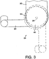
- a lever 30 is provided at the other end of the bar 20, attached to a vertical shaft 35 which is rotatably supported by the bar 20 and to which a circular disk 40 is eccentrically mounted, as shown in Fig. 3 .
- this eccentrically mounted disk 40 is adapted to rotate with and around the shaft 35 such that, when the lever 30 extends perpendicularly to the direction of extension of the bar 20 as shown by solid line in Fig. 3 , the center of the circular disk 40 is on the side of the shaft 35 towards the other end of the bar 20.
- the lever 30 is rotated such that the eccentrically mounted disk 40 will move towards the other end of the bar 12, thereby reducing the distance of separation between the fixed disk 25 and the eccentrically mounted rotatable disk 40.
- the separation between the pairs of indentations 15, the distance between the fixed disk 25 and the dimensions of the rotatable disk 40 including the eccentricity of its mounting to the shaft 35 are so determined that this rotation of the lever 30 causes the bar 20 to be clamped securely onto the panel 10 between the selected pair of indentations 15.
- the attachment is effected by a simple rotation by 90 degrees of the lever 30 from an unlocked position to a locked position. When locked, a clamp force is generated which effectively secures all three translational and three rotational degrees of freedom. Since the crescent-shaped indentations 15 are fixed, positioning is definitively precise and repeatable.
- the fixed disk 35 may be replaced by a member having a different shape, and the indentations 15 need not necessarily be crescent-shaped. Indentations of any shape capable of properly accepting and engaging such a fixed member to lock the bar can serve the purpose of this invention.
- the lever 30 may be replaced by any means for causing the eccentrically mounted disk 40 to be rotated around the shaft 35, including a cap adapted to start slipping after a certain maximum torque has been reached. As shown in Fig.
- an O-ring 50 may be used around the eccentrically mounted disk 40, as well as around the fixed disk 25 at the interface with the inner walls of the indentations 15 so as to distribute clamp force, to reduce wear, to accommodate variations in spacing with the arcuate inner walls of the indentations 15 and to keep the eccentrically mounted disk 40 from loosening by increasing sliding friction.
- indentations is intended to include configurations which may look more like a hole or a groove, as long as they have inner walls facing away from each other such that the fixed disk 25, or a member of any other shape which can reasonably substitute for it, and the eccentrically mounted disk 40 at opposite ends of the bar 20, as described above, can be received therein and cause the bar 20 to be locked to the panel 10.
- the bar 20 may be only a portion of the accessory to be clamped to the panel 10 or a mere representation of any target device which is intended to be clamped to the panel 10 and hence need not have all regular attributes of what one generally calls "a bar” such as being elongated or defining a direction of extension.
Landscapes
- Health & Medical Sciences (AREA)
- Life Sciences & Earth Sciences (AREA)
- Medical Informatics (AREA)
- Engineering & Computer Science (AREA)
- Radiology & Medical Imaging (AREA)
- Molecular Biology (AREA)
- Biophysics (AREA)
- Nuclear Medicine, Radiotherapy & Molecular Imaging (AREA)
- Optics & Photonics (AREA)
- Pathology (AREA)
- Physics & Mathematics (AREA)
- Biomedical Technology (AREA)
- Heart & Thoracic Surgery (AREA)
- High Energy & Nuclear Physics (AREA)
- Surgery (AREA)
- Animal Behavior & Ethology (AREA)
- General Health & Medical Sciences (AREA)
- Public Health (AREA)
- Veterinary Medicine (AREA)
- Surgical Instruments (AREA)
- Accommodation For Nursing Or Treatment Tables (AREA)
- Radiation-Therapy Devices (AREA)
- Clamps And Clips (AREA)
Description
- This invention relates to a system for clamping to a couch top an accessory such as a patient immobilization device for head and neck treatments or stereotactic radiotherapy.
- Current trends in general purpose radiotherapy are directed towards more clinically efficient setups and treatments. As a result, devices for locating patients require precise and repeatable repositioning of six (three translational and three rotational) degrees of freedom with quick and easy attachment. In addition, there exists a need for flexibility within the locating system to accommodate a broad range of body shapes and treatment sites.
- A precise and repeatable indexing system that is quick and easy to attach is currently not available. Attachment schemes tend to be incorporated either with minor modifications or non-repeatable clamping arrangements, and not directly integrated into the couch top design.
- Some more advanced prior art systems clamp to accessory rails which are found on most radiotherapy couches. Accessory rails are generally fixed lengthwise along the side of the couch top. The rail attachment itself will generally secure all six degrees of freedom, but not repeatably. Manual adjustment is required to re-establish at least one translational and one rotational degrees of freedom once the device is removed.
- Some devices possess an additional interface between such an accessory rail clamping system and the actual accessory. Pins protruding from either the rail clamping system or the accessory mate with clearance holes. This provides for one translational and two rotational degrees of freedom precisely secured and two translational and one rotational degrees of freedom loosely secured. Although quick and easy to attach, this is not a precise and repeatable locating system as a whole or even at the subsystem level.
- Locating systems that actually attach to the treatment surface are essentially custom jobs developed by individual hospital personnel. Pins protruding from either the couch top surface or the accessory mate with clearance holes. This also provides for one translational and two rotational degrees of freedom precisely secured and two translational and one rotational degrees of freedom loosely secured. Neither is this a precise and repeatable locating system since, by necessity, clearance exists between the hole and the pin.
- Capturing two treatment surface edges is another means of locating. Flanges attached to the accessory protrude below the surface of the couch securing one translational and two rotational degrees of freedom precisely and one translational and one rotational degrees of freedom loosely. This leaves one last degree of freedom left unsecured.
- Stereotactic head frames, although not considered for general purpose radiotherapy, do lock down six degrees of freedom, but they are not quick and easy to attach, being bolted in most cases. They do not secure to the treatment surface because a higher precision is required than in general purpose radiotherapy. Attachment is generally to the frame. These devices typically require a separate manual adjustment for precision fine tuning of position by using an external reference such as a laser.
-
FR-A-2 523 433 -
US-A-4 852 841 discloses a device for clamping to an edge of a table. The device has a top and bottom jaws for contacting top and bottom surfaces, respectively, of the table. -
US-A-4 394 800 discloses a guide clamp for clamping to a workpiece. The guide clamp includes a clamping jaw that is used to clamp against opposite sides of a workpiece. -
US-A-3 405 931 discloses a hammock configured for being mounted to an operating table. The hammock includes a clamp at a bottom, which is used to clamp agains opposite sides of the operating table. -
US-A-5 276 927 discloses a patient support table having side rails on opposite sides o the patient support table, and a head support slidably mounted to the side rails. -
US-A-5 152 486 discloses a surgical table having rails on opposite sides of the surgica table, and a surgical assistance device slidably mounted to the side rails. -
US-A-3 700 229 discloses an x-ray table that includes fastening strips secured to the sides of the table via slidable pieces. The slidable pieces have a T-shaped configuration, which prevents disengagement of the fastening strips from the table. -
US-A-2 301 804 discloses a bag holding apparatus configured to hold bags in position during the operation of filling or discharging material into the bags. - It is therefore an object of this invention to provide an improved clamping systen capable of quickly and easily clamping an accessory such as a patient immobilization device to a couch top for the patient with precision and repeatability.
- According to one aspect of the invention, there is provided an accessory clamping system as defined in claim 1.
- According to another aspect of the invention, there is provided an accessory clamping system as defined in
claim 10. - The accompanying drawings, which are incorporated in and form a part of this specification, illustrate an embodiment of the invention and, together with the description, serve to explain the principles of the invention. In the drawings:
-
Fig. 1 is an diagonal view of an accessory clamping system embodying this invention when a bar, which may be a part of an accessory to be clamped, is clamped to a couch top; -
Fig. 2 is an diagonal view of a portion of the accessory clamping system ofFig. 1 when the bar is about to be clamped to the couch top; and -
Fig. 3 is an enlarged plan view of the eccentrically mounted disk and the lever of the clamping system ofFigs. 1 and2 . - In
Figs. 1 and2 ,numeral 10 indicates a generally rectangular panel on a couch top, to which an accessory such as a patient immobilization device is adapted to be secured. Thepanel 10 is provided with pairs ofindexing indentations 15 on mutually opposite side edges, each pair having one of the indentations on one of the side edges and the other on the other of the side edges such that each pair of theindexing indentations 15 is transversely across the panel surface opposite to each other. According to a preferred embodiment of the invention, theseindentations 15 are crescent-shaped and convex towards the other of the pair. -
Numeral 20 indicates a bar which is to be secured onto thepanel 10 by making use of theseindexing indentations 15. It is approximately of the same length as the width of therectangular panel 10, that is, its length is about the same as the separation between each pair of theindexing indentations 15 and may be regarded as a part of an accessory such as a patient immobilization device or a frame to which such an accessory is adapted to be securely attached. - Attached to the lower surface of the
bar 20 at one of its ends is a circular disk-shaped member 25, herein referred to as the fixed disk, adapted to fit inside any of theseindexing indentations 15. Alever 30 is provided at the other end of thebar 20, attached to avertical shaft 35 which is rotatably supported by thebar 20 and to which acircular disk 40 is eccentrically mounted, as shown inFig. 3 . Thus, this eccentrically mounteddisk 40 is adapted to rotate with and around theshaft 35 such that, when thelever 30 extends perpendicularly to the direction of extension of thebar 20 as shown by solid line inFig. 3 , the center of thecircular disk 40 is on the side of theshaft 35 towards the other end of thebar 20. - Quick and easy attachment of the
bar 20 to thepanel 10 is accomplished by first rotating thelever 30 by 90 degrees to the direction away from the other end of thebar 20, as shown by dotted lines inFig. 3 , thereby also moving the eccentrically mounteddisk 40 away from the other end of thebar 20, that is, increasing the distance between the twodisks bar 20 by a small distance determined by the eccentricity of the mounting of therotatable disk 40. With thelever 30 thus oriented, thebar 20 is positioned as shown inFig. 2 such that thefixed disk 25 and the eccentrically mounteddisk 40 are each fit inside a corresponding one of a selected pair of theindexing indentations 15. Thereafter, thelever 30 is rotated such that the eccentrically mounteddisk 40 will move towards the other end of the bar 12, thereby reducing the distance of separation between the fixeddisk 25 and the eccentrically mountedrotatable disk 40. The separation between the pairs ofindentations 15, the distance between thefixed disk 25 and the dimensions of therotatable disk 40 including the eccentricity of its mounting to theshaft 35 are so determined that this rotation of thelever 30 causes thebar 20 to be clamped securely onto thepanel 10 between the selected pair ofindentations 15. In other words, the attachment is effected by a simple rotation by 90 degrees of thelever 30 from an unlocked position to a locked position. When locked, a clamp force is generated which effectively secures all three translational and three rotational degrees of freedom. Since the crescent-shaped indentations 15 are fixed, positioning is definitively precise and repeatable. - The invention has been described above with reference to only one example but the illustrated example is not intended to limit the scope of this invention. Many modifications and variations are possible within the scope of the invention. For example, the fixed
disk 35 may be replaced by a member having a different shape, and theindentations 15 need not necessarily be crescent-shaped. Indentations of any shape capable of properly accepting and engaging such a fixed member to lock the bar can serve the purpose of this invention. Thelever 30 may be replaced by any means for causing the eccentrically mounteddisk 40 to be rotated around theshaft 35, including a cap adapted to start slipping after a certain maximum torque has been reached. As shown inFig. 3 , an O-ring 50 may be used around the eccentrically mounteddisk 40, as well as around the fixeddisk 25 at the interface with the inner walls of theindentations 15 so as to distribute clamp force, to reduce wear, to accommodate variations in spacing with the arcuate inner walls of theindentations 15 and to keep the eccentrically mounteddisk 40 from loosening by increasing sliding friction. - The language in the specification, as well as in the claims, is intended to be interpreted broadly. The expression "indentations", for example, is intended to include configurations which may look more like a hole or a groove, as long as they have inner walls facing away from each other such that the fixed
disk 25, or a member of any other shape which can reasonably substitute for it, and the eccentrically mounteddisk 40 at opposite ends of thebar 20, as described above, can be received therein and cause thebar 20 to be locked to thepanel 10. - It is also to be reminded that the
bar 20, as used above in the description, may be only a portion of the accessory to be clamped to thepanel 10 or a mere representation of any target device which is intended to be clamped to thepanel 10 and hence need not have all regular attributes of what one generally calls "a bar" such as being elongated or defining a direction of extension.
Claims (21)
- An accessory clamping system, comprising:a patient support panel (10) configured for allowing a target device (20) to be coupled thereto, the patient support panel (10) supporting the target device (20) after the target device (20) is coupled thereto, the patient support panel (10) having a length along a longitudinal side of the patient support panel (10), and a pair of indentations that include a first indentation (15) and a second indentation (15), the target device (20) having a first member (40), a second member (25), and a rotation mechanism (30);characterized in that:each of the first and second indentations has inner walls facing away from each other;the first member (40) comprises a first circular disk-shaped member that is eccentrically mounted;the second member (25) comprises a second circular disk-shaped member;the rotation mechanism (30) is configured to rotate the first circular disk-shaped member; andthe first and second circular disk-shaped members are configured to engage against the respective first and second indentations (15).
- The accessory clamping system of claim 1, wherein the patient support panel (10) is a part of a couch top.
- The accessory clamping system of claim 1 or 2, wherein one or both of the first and second indentations (15) comprises a hole or a groove.
- The accessory clamping system of any one of claims 1 to 3, wherein each of the first and second indentations (15) has a curved surface.
- The accessory clamping system of any one of claims 1 to 4, wherein the patient support panel (10) further comprises one or more additional pair(s) of indentations (15) to which the first and second members (25) can be engaged.
- The accessory clamping system of any one of claims 1 to 5, wherein the first and second indentations (15) are located on opposite edges of the patient support panel (10).
- The accessory clamping system of any one of claims 1 to 6, further comprising the target device (20).
- The accessory clamping system of any one of claims 1 to 7, wherein the first member (25) is configured to be kept from loosening from the first indentation (15) by increasing sliding friction.
- The accessory clamping system of any one of claims 7 to 8, wherein the patient support panel (10) includes additional pair(s) of indentations (15) to which the first member (25) can be engaged.
- An accessory clamping system, comprising:a target device (20) configured to be coupled to the patient support panel (10) as defined in claim 1, the target device (20) supported by the patient support panel (10) after the target device (20) is coupled to the patient support panel (10), the patient support panel (10) having a length along a longitudinal side, and a pair of indentations that include a first indentation and a second indentation (15), the target device (20) having a first end, a second end, a first member (40) coupled to the first end, and a second member (25) coupled to the second end;characterized in that:each of the first and second indentations (15) has inner walls facing away from each other;the first member (40) comprises a first circular disk-shaped member that is eccentrically mounted;the second member (25) comprises a second circular disk-shaped member;the target device (20) further comprises a rotation mechanism (30) configured to rotate the first circular disk-shaped member; andthe first and second circular disk-shaped members are configured to engage against the respective first and second indentations (15) of the patient support panel.
- The accessory clamping system of claim 10, wherein the target device (20) comprises at least a portion of an accessory.
- The accessory clamping system of claim 10, wherein the target device (20) comprises a structure to which an accessory can be attached.
- The accessory clamping system of claim 11 or 12, wherein the accessory is a patient immobilization device.
- The accessory clamping system of any one of claims 10 to 13, wherein the target device (20) has a dimension that is approximately the same as a width of the patient support panel (10).
- The accessory clamping system of any one of claims 10 to 14, wherein the first and second members (25) are separated by a distance which is approximately the same as a separation between the first and second indentations (15).
- The accessory clamping system of any one of claims 10 to 15, wherein each of the first and second indentations (15) has a curved surface.
- The accessory clamping system of any one of claims 10 to 16, wherein the first member (25) is configured to be kept from loosening from the first indentation (15) by increasing sliding friction.
- The accessory clamping system of claim 10, wherein the first circular disk-shaped member is eccentrically mounted to a shaft (35) that is rotatably supported by the target device (20).
- The accessory clamping system of claim 18, wherein the rotation mechanism is configured for rotating the first circular disk-shaped member around the shaft (35) to thereby secure the target device (20) to the panel (10).
- The accessory clamping system of any one of claims 10 to 19, further comprising the patient support panel (10).
- The accessory clamping system of any one of claims 10 to 20, wherein the patient support panel (10) includes additional pair(s) of indentations (15) to which the first and second members (25) can be engaged.
Applications Claiming Priority (3)
| Application Number | Priority Date | Filing Date | Title |
|---|---|---|---|
| US738429 | 1996-10-25 | ||
| US08/738,429 US5806116A (en) | 1996-10-25 | 1996-10-25 | Positioning system for a patient support apparatus |
| EP97913771A EP0891153A1 (en) | 1996-10-25 | 1997-10-24 | Accessory clamping system for couch top |
Related Parent Applications (1)
| Application Number | Title | Priority Date | Filing Date |
|---|---|---|---|
| EP97913771A Division EP0891153A1 (en) | 1996-10-25 | 1997-10-24 | Accessory clamping system for couch top |
Publications (3)
| Publication Number | Publication Date |
|---|---|
| EP1366714A2 EP1366714A2 (en) | 2003-12-03 |
| EP1366714A3 EP1366714A3 (en) | 2005-01-26 |
| EP1366714B1 true EP1366714B1 (en) | 2017-02-15 |
Family
ID=24967986
Family Applications (2)
| Application Number | Title | Priority Date | Filing Date |
|---|---|---|---|
| EP03015376.1A Expired - Lifetime EP1366714B1 (en) | 1996-10-25 | 1997-10-24 | Accessory clamping system for couch top |
| EP97913771A Withdrawn EP0891153A1 (en) | 1996-10-25 | 1997-10-24 | Accessory clamping system for couch top |
Family Applications After (1)
| Application Number | Title | Priority Date | Filing Date |
|---|---|---|---|
| EP97913771A Withdrawn EP0891153A1 (en) | 1996-10-25 | 1997-10-24 | Accessory clamping system for couch top |
Country Status (3)
| Country | Link |
|---|---|
| US (1) | US5806116A (en) |
| EP (2) | EP1366714B1 (en) |
| WO (1) | WO1998017176A1 (en) |
Families Citing this family (31)
| Publication number | Priority date | Publication date | Assignee | Title |
|---|---|---|---|---|
| US6161237A (en) * | 1999-07-29 | 2000-12-19 | Med-Tec, Inc. | Patient positioning device for radiation therapy |
| US6484332B2 (en) | 1999-12-08 | 2002-11-26 | Med-Tec Iowa, Inc. | System for vertical to horizontal movement and lateral movement of a patient |
| US6904630B2 (en) | 2000-07-21 | 2005-06-14 | Siemens Medical Solutions Usa, Inc. | Tabletop for radiation therapy and diagnostic imaging |
| JP2002308716A (en) * | 2001-04-06 | 2002-10-23 | Isi:Kk | Fine particle coated with monodisperse super thin film and cosmetic using the same |
| US7769430B2 (en) * | 2001-06-26 | 2010-08-03 | Varian Medical Systems, Inc. | Patient visual instruction techniques for synchronizing breathing with a medical procedure |
| ES2283624T3 (en) | 2001-10-30 | 2007-11-01 | Loma Linda University Medical Center | DEVICE TO ALIGN A PATIENT FOR THE ADMINISTRATION OF RADIOTHERAPY. |
| US6895617B2 (en) * | 2002-08-20 | 2005-05-24 | Aktina Corp. | Patient support system and elements thereof |
| US6941599B2 (en) * | 2002-08-20 | 2005-09-13 | Aktina Medical Corp. | Radiotherapy treatment and imaging patient support table |
| US7063461B2 (en) * | 2002-11-21 | 2006-06-20 | Qfix Systems, Llc | Patient support device with shoulder depression device |
| US20040133980A1 (en) * | 2003-01-15 | 2004-07-15 | Coppens Daniel D. | Indexing positioning system for accurate and repetitive positioning of patients in a multimodal environment |
| US20040159325A1 (en) * | 2003-02-19 | 2004-08-19 | Med-Tec | Indexing system for radiation therapy |
| KR101081839B1 (en) | 2003-08-12 | 2011-11-09 | 로마 린다 유니버시티 메디칼 센터 | Modular patient support system |
| US7174587B2 (en) * | 2003-10-17 | 2007-02-13 | Analogic Corporation | Patient positioning device for radiation therapy |
| US7836890B2 (en) * | 2003-10-17 | 2010-11-23 | Diacor, Inc. | Systems for immobilization of a patient for diagnosis and treatment of breast tissue |
| US7073508B2 (en) * | 2004-06-25 | 2006-07-11 | Loma Linda University Medical Center | Method and device for registration and immobilization |
| US20060074305A1 (en) * | 2004-09-30 | 2006-04-06 | Varian Medical Systems Technologies, Inc. | Patient multimedia display |
| WO2006083703A2 (en) * | 2005-01-28 | 2006-08-10 | Indiana University Research & Technology Corporation | Method for radiation therapy delivery at varying source to target distances |
| US9119541B2 (en) * | 2005-08-30 | 2015-09-01 | Varian Medical Systems, Inc. | Eyewear for patient prompting |
| EP1937109B1 (en) * | 2005-09-24 | 2015-03-25 | Qfix Systems, LLC | Radiation therapy patient couch top compatible with diagnostic imaging |
| US7581884B1 (en) * | 2006-02-07 | 2009-09-01 | Barnes Gary T | Mobile radiography system and grid alignment process |
| GB2451372B (en) * | 2006-04-27 | 2011-09-14 | Qfix System Llc | A method for creating 3D coordinate systems in image space for device and patient table location and verification |
| JP5448831B2 (en) | 2006-11-21 | 2014-03-19 | ローマ リンダ ユニヴァーシティ メディカル センター | Apparatus and method for securing a patient for breast radiation therapy |
| US8146599B2 (en) | 2008-06-17 | 2012-04-03 | Civco Medical Instruments Co., Inc. | Patient positioning system |
| GB0911307D0 (en) * | 2009-06-30 | 2009-08-12 | Omnia Cs Ltd | Table |
| US20120167898A1 (en) * | 2010-12-29 | 2012-07-05 | Indiana University Research And Technology Corporation | Patient Immobilization Device For Radiotherapy Treatment System And Methods |
| US10292888B2 (en) | 2013-12-18 | 2019-05-21 | Medtec, Inc. | Bridge device for a patient positioning system |
| US10603513B2 (en) | 2014-07-22 | 2020-03-31 | Qfix Systems, Llc | Patient transfer support locating device |
| US11564589B2 (en) | 2015-03-04 | 2023-01-31 | Koninklijke Philips N.V. | Patient table assembly |
| JP6999121B2 (en) * | 2016-06-24 | 2022-01-18 | 凸版印刷株式会社 | Rock bar |
| TWI771787B (en) * | 2020-10-30 | 2022-07-21 | 國立中央大學 | A method of radiographic localization |
| US20240050769A1 (en) * | 2020-10-30 | 2024-02-15 | Patricia H Hardenbergh | Breast immobilization device |
Family Cites Families (12)
| Publication number | Priority date | Publication date | Assignee | Title |
|---|---|---|---|---|
| US2301804A (en) * | 1940-08-03 | 1942-11-10 | Allis Chalmers Mfg Co | Bag holding apparatus |
| US3405931A (en) * | 1966-04-19 | 1968-10-15 | Anderson Roger | Operating table hammock |
| US3700229A (en) * | 1969-09-29 | 1972-10-24 | Toshio Kurokawa | Examinee fastening device for use in an x-ray photographing apparatus |
| US3814419A (en) * | 1973-06-04 | 1974-06-04 | L Bjorklund | Arm exercising device |
| US3840221A (en) * | 1973-09-04 | 1974-10-08 | W Hogan | Top-within-top for x-ray table |
| US3981492A (en) * | 1975-08-04 | 1976-09-21 | Hallmann David R | X-ray table patient transfer device or the like with body holding device |
| US4394800A (en) * | 1981-12-03 | 1983-07-26 | Norman Griset | Guide clamp |
| FR2523433A1 (en) * | 1982-03-18 | 1983-09-23 | Beal Joseph | Swivelling support for examination of chilo on radiology table - has fixed frame with height and rotation adjustable and lockable board |
| US4852841A (en) * | 1988-10-12 | 1989-08-01 | Sebring John P | Device for clamping the edge of a table |
| US5152486A (en) * | 1991-04-12 | 1992-10-06 | Kabanek Joseph R | Operating room table mate |
| US5276927A (en) * | 1992-09-21 | 1994-01-11 | Ohio Medical Instrument Co. | Radiolucent head support |
| US5385119A (en) * | 1993-04-27 | 1995-01-31 | Tarulli; Joseph R. | X-ray positioner and restraining device |
-
1996
- 1996-10-25 US US08/738,429 patent/US5806116A/en not_active Expired - Lifetime
-
1997
- 1997-10-24 EP EP03015376.1A patent/EP1366714B1/en not_active Expired - Lifetime
- 1997-10-24 EP EP97913771A patent/EP0891153A1/en not_active Withdrawn
- 1997-10-24 WO PCT/US1997/019335 patent/WO1998017176A1/en not_active Ceased
Non-Patent Citations (1)
| Title |
|---|
| None * |
Also Published As
| Publication number | Publication date |
|---|---|
| EP1366714A3 (en) | 2005-01-26 |
| US5806116A (en) | 1998-09-15 |
| WO1998017176A1 (en) | 1998-04-30 |
| EP0891153A1 (en) | 1999-01-20 |
| EP1366714A2 (en) | 2003-12-03 |
Similar Documents
| Publication | Publication Date | Title |
|---|---|---|
| EP1366714A2 (en) | Accessory clamping system for couch top | |
| US6003174A (en) | Radiolucent table extension and method | |
| US4624245A (en) | Hip displacement apparatus | |
| EP0660694B1 (en) | Radiolucent head support | |
| EP3085349B1 (en) | Rotatable seat clamps for rail clamp | |
| US6311349B1 (en) | Pelvic positioner | |
| US6671904B2 (en) | Surgical table top and accessory clamp used thereon | |
| US5741210A (en) | Clamping device for a surgical retractor | |
| US5085219A (en) | Adjustable holders for magnetic reasonance imaging rf surface coil | |
| US6912959B2 (en) | Surgical table and clamp system | |
| US4786022A (en) | Attaching device | |
| US6813788B2 (en) | Variable length radiolucent surgical table extension | |
| US6023800A (en) | Removable accessory for a surgical table | |
| US5422928A (en) | Apparatus for mounting a backboard to a gurney | |
| US4467791A (en) | Surgical retractor holder | |
| EP3116462B1 (en) | Limb positioning system | |
| US4064401A (en) | Headholder assembly | |
| JP2004513748A (en) | Device for retaining accessories on patient support surface | |
| CA1086171A (en) | Head support and restraining apparatus | |
| US20250268772A1 (en) | Systems and methods for patient positioning | |
| KR20010023551A (en) | Radiolucent table extension assembly | |
| US12575990B2 (en) | System for prone positioning of surgical patients | |
| JPH07299059A (en) | Medical sleeper | |
| CN112451119B (en) | Head fixation device for intracranial aneurysm interventional surgery | |
| JPH0571512A (en) | Grip device |
Legal Events
| Date | Code | Title | Description |
|---|---|---|---|
| PUAI | Public reference made under article 153(3) epc to a published international application that has entered the european phase |
Free format text: ORIGINAL CODE: 0009012 |
|
| AC | Divisional application: reference to earlier application |
Ref document number: 0891153 Country of ref document: EP Kind code of ref document: P |
|
| AK | Designated contracting states |
Kind code of ref document: A2 Designated state(s): DE GB |
|
| RIN1 | Information on inventor provided before grant (corrected) |
Inventor name: HAUGHER, TODD M. Inventor name: OLIVER, EDWARD A. |
|
| PUAL | Search report despatched |
Free format text: ORIGINAL CODE: 0009013 |
|
| AK | Designated contracting states |
Kind code of ref document: A3 Designated state(s): DE GB |
|
| AKX | Designation fees paid | ||
| RBV | Designated contracting states (corrected) |
Designated state(s): DE GB |
|
| 17P | Request for examination filed |
Effective date: 20050720 |
|
| REG | Reference to a national code |
Ref country code: DE Ref legal event code: 8566 |
|
| 17Q | First examination report despatched |
Effective date: 20051128 |
|
| RAP1 | Party data changed (applicant data changed or rights of an application transferred) |
Owner name: VARIAN MEDICAL SYSTEMS, INC. |
|
| GRAP | Despatch of communication of intention to grant a patent |
Free format text: ORIGINAL CODE: EPIDOSNIGR1 |
|
| INTG | Intention to grant announced |
Effective date: 20160713 |
|
| GRAJ | Information related to disapproval of communication of intention to grant by the applicant or resumption of examination proceedings by the epo deleted |
Free format text: ORIGINAL CODE: EPIDOSDIGR1 |
|
| STAA | Information on the status of an ep patent application or granted ep patent |
Free format text: STATUS: EXAMINATION IS IN PROGRESS |
|
| GRAS | Grant fee paid |
Free format text: ORIGINAL CODE: EPIDOSNIGR3 |
|
| STAA | Information on the status of an ep patent application or granted ep patent |
Free format text: STATUS: GRANT OF PATENT IS INTENDED |
|
| GRAP | Despatch of communication of intention to grant a patent |
Free format text: ORIGINAL CODE: EPIDOSNIGR1 |
|
| INTC | Intention to grant announced (deleted) | ||
| GRAA | (expected) grant |
Free format text: ORIGINAL CODE: 0009210 |
|
| STAA | Information on the status of an ep patent application or granted ep patent |
Free format text: STATUS: THE PATENT HAS BEEN GRANTED |
|
| INTG | Intention to grant announced |
Effective date: 20161223 |
|
| AC | Divisional application: reference to earlier application |
Ref document number: 0891153 Country of ref document: EP Kind code of ref document: P |
|
| AK | Designated contracting states |
Kind code of ref document: B1 Designated state(s): DE GB |
|
| REG | Reference to a national code |
Ref country code: GB Ref legal event code: FG4D |
|
| REG | Reference to a national code |
Ref country code: DE Ref legal event code: R096 Ref document number: 69740886 Country of ref document: DE |
|
| REG | Reference to a national code |
Ref country code: DE Ref legal event code: R071 Ref document number: 69740886 Country of ref document: DE |
|
| REG | Reference to a national code |
Ref country code: DE Ref legal event code: R097 Ref document number: 69740886 Country of ref document: DE |
|
| PLBE | No opposition filed within time limit |
Free format text: ORIGINAL CODE: 0009261 |
|
| STAA | Information on the status of an ep patent application or granted ep patent |
Free format text: STATUS: NO OPPOSITION FILED WITHIN TIME LIMIT |
|
| 26N | No opposition filed |
Effective date: 20171116 |
|
| REG | Reference to a national code |
Ref country code: GB Ref legal event code: PE20 Expiry date: 20171023 |
|
| PG25 | Lapsed in a contracting state [announced via postgrant information from national office to epo] |
Ref country code: GB Free format text: LAPSE BECAUSE OF EXPIRATION OF PROTECTION Effective date: 20171023 |