EP1366613B1 - Address translator and address translation method - Google Patents
Address translator and address translation method Download PDFInfo
- Publication number
- EP1366613B1 EP1366613B1 EP02706919A EP02706919A EP1366613B1 EP 1366613 B1 EP1366613 B1 EP 1366613B1 EP 02706919 A EP02706919 A EP 02706919A EP 02706919 A EP02706919 A EP 02706919A EP 1366613 B1 EP1366613 B1 EP 1366613B1
- Authority
- EP
- European Patent Office
- Prior art keywords
- network
- address
- alias
- communication
- ipv6
- Prior art date
- Legal status (The legal status is an assumption and is not a legal conclusion. Google has not performed a legal analysis and makes no representation as to the accuracy of the status listed.)
- Expired - Lifetime
Links
Images





Classifications
-
- H—ELECTRICITY
- H04—ELECTRIC COMMUNICATION TECHNIQUE
- H04L—TRANSMISSION OF DIGITAL INFORMATION, e.g. TELEGRAPHIC COMMUNICATION
- H04L61/00—Network arrangements, protocols or services for addressing or naming
- H04L61/09—Mapping addresses
- H04L61/25—Mapping addresses of the same type
- H04L61/2503—Translation of Internet protocol [IP] addresses
- H04L61/251—Translation of Internet protocol [IP] addresses between different IP versions
-
- H—ELECTRICITY
- H04—ELECTRIC COMMUNICATION TECHNIQUE
- H04L—TRANSMISSION OF DIGITAL INFORMATION, e.g. TELEGRAPHIC COMMUNICATION
- H04L61/00—Network arrangements, protocols or services for addressing or naming
-
- H—ELECTRICITY
- H04—ELECTRIC COMMUNICATION TECHNIQUE
- H04L—TRANSMISSION OF DIGITAL INFORMATION, e.g. TELEGRAPHIC COMMUNICATION
- H04L67/00—Network arrangements or protocols for supporting network services or applications
- H04L67/01—Protocols
- H04L67/10—Protocols in which an application is distributed across nodes in the network
- H04L67/1001—Protocols in which an application is distributed across nodes in the network for accessing one among a plurality of replicated servers
-
- H—ELECTRICITY
- H04—ELECTRIC COMMUNICATION TECHNIQUE
- H04L—TRANSMISSION OF DIGITAL INFORMATION, e.g. TELEGRAPHIC COMMUNICATION
- H04L69/00—Network arrangements, protocols or services independent of the application payload and not provided for in the other groups of this subclass
- H04L69/08—Protocols for interworking; Protocol conversion
-
- H—ELECTRICITY
- H04—ELECTRIC COMMUNICATION TECHNIQUE
- H04L—TRANSMISSION OF DIGITAL INFORMATION, e.g. TELEGRAPHIC COMMUNICATION
- H04L67/00—Network arrangements or protocols for supporting network services or applications
- H04L67/01—Protocols
- H04L67/10—Protocols in which an application is distributed across nodes in the network
- H04L67/1001—Protocols in which an application is distributed across nodes in the network for accessing one among a plurality of replicated servers
- H04L67/10015—Access to distributed or replicated servers, e.g. using brokers
-
- H—ELECTRICITY
- H04—ELECTRIC COMMUNICATION TECHNIQUE
- H04L—TRANSMISSION OF DIGITAL INFORMATION, e.g. TELEGRAPHIC COMMUNICATION
- H04L67/00—Network arrangements or protocols for supporting network services or applications
- H04L67/01—Protocols
- H04L67/10—Protocols in which an application is distributed across nodes in the network
- H04L67/1001—Protocols in which an application is distributed across nodes in the network for accessing one among a plurality of replicated servers
- H04L67/1004—Server selection for load balancing
- H04L67/1008—Server selection for load balancing based on parameters of servers, e.g. available memory or workload
-
- H—ELECTRICITY
- H04—ELECTRIC COMMUNICATION TECHNIQUE
- H04L—TRANSMISSION OF DIGITAL INFORMATION, e.g. TELEGRAPHIC COMMUNICATION
- H04L67/00—Network arrangements or protocols for supporting network services or applications
- H04L67/01—Protocols
- H04L67/10—Protocols in which an application is distributed across nodes in the network
- H04L67/1001—Protocols in which an application is distributed across nodes in the network for accessing one among a plurality of replicated servers
- H04L67/1004—Server selection for load balancing
- H04L67/101—Server selection for load balancing based on network conditions
-
- H—ELECTRICITY
- H04—ELECTRIC COMMUNICATION TECHNIQUE
- H04L—TRANSMISSION OF DIGITAL INFORMATION, e.g. TELEGRAPHIC COMMUNICATION
- H04L67/00—Network arrangements or protocols for supporting network services or applications
- H04L67/01—Protocols
- H04L67/10—Protocols in which an application is distributed across nodes in the network
- H04L67/1001—Protocols in which an application is distributed across nodes in the network for accessing one among a plurality of replicated servers
- H04L67/1004—Server selection for load balancing
- H04L67/1014—Server selection for load balancing based on the content of a request
Definitions
- This invention relates to an address translator, and is suitable particularly, but not exclusively, for address translation between different networks.
- IP Internet Protocol
- IPv6 IPv6 is a totally different protocol to IPv4 and is fundamentally incompatible with IPv4. Therefore, during the transitory period at least, network devices and/or networks will require mechanisms to enable a node and/or host in an IPv4 network, having an IPv4 address, to communicate with a node and/or host in an IPv6 network, having an IPv6 address.
- a problem with at least some of known migration methods is that they have been designed and operated in a test environment, and have not been subjected to the volume of traffic experienced in commercial IP networks. There has therefore been little work carried out on designing migration methods that are commercially scalable and robust. This could be a serious problem, given that the transition between IPv4 and IPv6 is expected to be long, and the volume of IP traffic is continually increasing.
- apparatus for providing communication between a network device in a first network and a network device in a second network, where the first network operates in accordance with a first communication protocol and the second network operates in accordance with a second communication protocol.
- the apparatus comprises
- Particularly advantageous embodiments of the invention are applied between IPv4 and IPv6 networks, so that the first network is a IPv4 network and the second network is a IPv6 network.
- the alias comprises a network address, and when the communication is being sent into an IPv6 network, the network address includes an identifier representative of the second means.
- the second means comprises a plurality of further devices.
- the first means upon assignment of alias to the target network device, effectively causes subsequent communications to occur via one of a plurality of further devices.
- Having a plurality of devices advantageously introduces resilience, scalability and efficient management of network loading.
- each further device has access to one or more groups of aliases, and each group can be stored in a store.
- each group can be stored in a store.
- two or more groups can be stored in a store.
- inventions include selecting means for selecting one of the plurality of further devices in accordance with predetermined criteria, such as device characteristics.
- the selecting means is operable to monitor the device characteristics, so that selection of a device is based on current device performance. Monitored device characteristics include at least one of operational status of device, loading on device, and/or aliases available to the device.
- the selecting means is in operative association with the first means, so that the first means is operable to retrieve an alias available to the further device, which retrieved alias is the assigned alias.
- mapping store for storing mappings between the assigned alias and the network device assigned to the alias.
- the mapping store can be managed by the first means, a database, or by the further device.
- the selection of manager of the mapping stored is typically subject to criteria such as network traffic, ownership of network devices and transmission paths.
- Embodiments of the invention are concerned with issues relating to migration from IPv4 to IPv6 networks. Specifically, embodiments of the invention are concerned with scalability aspects of migration methods; as stated above, almost all of the IPv6 networks currently in operation are "test" networks and are not subject to the volume of IP traffic passing through commercial IP networks. Thus the performance of the migration methods in a commercial environment may be unacceptably low.
- NAT-PT Network Address Translator - Protocol Translator
- NAT-PT is a stateful translation process, meaning that there is specific information that must be retained in order for each individual session to be translated.
- NAT-PT Network Address Translation
- DNS_ALG DNS Application Level Gateway
- Figure 1 shows a conventional implementation of NAT-PT in operation between a first network NW1, which may be an IPv4 network and a second network NW2, which may be an IPv6 network.
- the implementation includes a single translator 101, which comprises processes 102 that manage assignment of IPv6/v4 addresses. Such processes 102 include the DNS application level gateway.
- the translator 101 has access to a pool 103 of IPv4 addresses, which is used for assignment to IPv6 nodes.
- Figure 1 additionally shows two DNS servers 104, 106, a first 104 of which stores IPv4 name to address mappings in the form of "A" records, and a second 106 of which stores IPv6 name to address mappings in the form of "AAAA" records.
- the translator 101 is typically located on a border router, referred to as an ingress interface with respect to the IPv6 network NW2.
- an ingress interface with respect to the IPv6 network NW2.
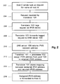
- FIG. 2 Conventional operation of this known NAT-PT implementation is shown in Figure 2 .
- host C in the IPv4 network sends 202 a name lookup request for host A in the IPv6 network.
- This lookup request is termed an "A" type DNS request.
- This request is received 204 by the translator 101, which tags 206 the request as an IPv6 record request, so that the request becomes an "AAAA" type DNS request, and forwards 208 the tagged request to the DNS server 106.
- the DNS server 106 replies 210, returning an IPv6 network address to the translator 101, which, in co-operation with the processes 102, assigns 212 an IPv4 address from the pool of addresses to the returned IPv6 address.
- the translator 101 stores 214 the mapping between the assigned IPv4 address and the returned IPv6 address, and forwards 216 the assigned IPv4 address to the requesting host C.
- host C sets 302 the destination address to be the assigned IPv4 address for outgoing packets, and sends 304 the packets to the assigned IPv4 address of Host A, and conventional IP routing ensures that the packet routes to the translator 101.
- the translator 101 looks up 306 the mapping between assigned IPv4 address and IPv6 address to retrieve the IPv6 address of host A, and makes this 308 the destination address of the packet.
- the translator 101 For the packets to be routed from the translator 101 to host A, the translator 101 has to modify the source address of the packet, which is the IPv4 address of node C, into IPv6 format. This involves expanding 310 the IPv4 address of host C with a prefix that is representative of the translator 101. As is well known, an IPv4 address is 32bits long, whereas an IPv6 address is 128bits long. As stated above, an IPv6 host cannot interpret an IPv4 address, and vice-versa - because of the differences in address length. Thus when an IPv4 packet arrives at the translator 101 a 96bit prefix, which is indicative of the translator 101, is added to the source address of the packet (32bits) to make an IPv6 address (128bits).
- IPv6 address Packets sent to this IPv6 address will then be routed to the translator 101.
- an IPv4 source address 10.10.10.10 arriving at the translator 101 could be given the prefix 2001:618:1:2:: so that the source IPv4 host has the following address in the IPv6 world: 2001:618:1:2::10.10.10.10.
- An IPv6 packet sent to this address would go to translator 101 because the prefix 2001:628:1:2:: routes to the translator 101.
- the translator 101 then sends 312 the packet, using the expanded IPv6 address. All subsequent communications between host A and host C can make use of the mappings stored in the translator 101.
- the translator 101 performs translation of packets as they pass between hosts (C) in the IPv4 network and hosts (A) in the IPv6 network, thus acting as a medium for all communication between said hosts A, C.
- a problem with this configuration is that centralized address assignment and communications processing could present scalability problems when IPv6 networks become mainstream.
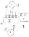
- the translator 400 essentially comprises two components: a controller 401 and a plurality of devices 403a, 403b ... 403n (hereinafter collectively referred to as 403 i ).
- Requests to communicate with hosts in the IPv"other" network are received by the controller 401, which polls the devices 403 i in order to identify one that has capacity to service the request.
- a device so identified thereafter deals with all subsequent communication between hosts in IPv6 and IPv4, and the subsequent communication is therefore independent of the controller operations.
- the configuration and functionality of these components is described in more detail below.
- address assignment events are separated from subsequent communication events between hosts in IPv4 and IPv6 networks (e.g. translating packets using the assigned addresses).
- the controller 401 can select from a plurality of devices for address assignment.
- the controller 401 receives DNS requests initiated by hosts in either the IPv4 or the IPv6 networks, and manages DNS lookups, in the manner described above, in respect of the requests. Having received a returned IPvn address from a respective DNS server 104, 106, the controller 401 then identifies a device 403 i that will mediate for subsequent communications between the requesting host (in the example above, host C) and the destination host (in the example above, host A). Each device has a globally routable prefix (i.e. a prefix that is appended to destination addresses of packets destined for the device), which, when appended to an IPv4 address, enables packets to reach the device (as described above).
- a globally routable prefix i.e. a prefix that is appended to destination addresses of packets destined for the device
- identification of a device 403 i comprises determining whether the device 403 i is up and running.
- the controller 401 identifies whether there are any free addresses available to the device 403 i , and the current loading on, or the number of communications that are currently being handled by, a device.
- the controller 401 may run a program 411, which polls each device 403 i at predetermined intervals to determine current loading, operational status and IP addresses accessible to that device.
- the program 411 gathers the loading and address availability data from the devices 403 i , and stores it, for example as a list in memory.
- the controller 401 may run the program 411 at predetermined intervals, for example every second, or as frequently as required to capture changes to the devices 403 i .
- the controller 401 may also run selection algorithms for selecting a device 403 a from the list. For example, a typical selection algorithm 412 searches the list for an operational device that has access to at least one free IPv4 address and that has a loading below a predetermined threshold. If more than one device satisfies these criteria, then the device with lowest loading is selected. Many variations on this example are possible, and would be apparent to the skilled person.
- each device 403 i may be a conventional router, so that the controller 401 can derive the loading on a device 403 a by issuing Simple Network Management Protocol (SNMP) messages to a Management Information Base (MIB) that is maintained on the router.
- SNMP is part of the known TCP/IP network software, and MIB, or Management Information Base, is a standard specifying the data items that a host, router or switch must keep, together with the operations allowed on each.
- MIB Management Information Base
- SNMP is the protocol that enables information to be extracted from a MIB, and is known to those skilled in the art.
- each of the devices 403 i has access to a pool 405 of IPv4 addresses, and the availability, to any single device 403 a of IP addresses, is recorded on a respective device 403.
- the controller 405 could therefore determine address availability per device 403 by reviewing the record of address availability thereon. The skilled person would realize that such a record does not need to be stored on the devices themselves, but could be held centrally, e.g. in a database.
- the pool 405 can either be a central pool, as is shown in Figure 4 , and accessible by all of the devices 403 i , or can comprise a plurality of pools, each accessible to a limited number of the devices 403 i .
- there may be one pool 405 per device 403 i as shown in Figure 5a
- there may be one pool 405 per n devices 403 i as shown in Figures 5b and 5c .
- the controller 401 may comprise one or more programs running on a processor, such as a conventional client or server computer. Alternatively the controller 401 could run on a router. In either configuration, the controller 401 could connect to each of the devices 403 i via dedicated links or via the Internet; if security were a consideration, dedicated links would be more suitable. As an alternative, a security protocol, such as IPsec, which is a mandatory part of IPv6, could be used for communications between controller 401 and devices 403 i .
- the programs can include socket processes that listen for incoming DNS lookup requests and listen for requests from devices 403 i .
- the controller 401 processes incoming requests on a FIFO (First-in, First-out) basis - i.e. the controller 401 implements a queuing discipline in which entities (here requests, incoming packets) are stored in a queue (or in the stack) and are serviced in the same order in which they arrive.
- the controller 401 could process requests in accordance with LIFO (last-in, first-out), where the most recent request is handled next and the oldest request doesn't get handled until it is the only remaining request on the queue (or in the stack).
- LIFO last-in, first-out
- scheduling policies are possible, e.g. when the controller 401 is subject to constraints; a suitable scheduling policy could utilise some sort of heuristic method (or combination of heuristic methods) in an attempt to schedule the requests so as to satisfy the constraint criteria.
- the scheduling policy could make use of Quality of Service information included in IPv6 headers: certain bits in the IP header indicate the priority of the request, and the controller 401 could include means for examining these bits (not shown).
- the controller 401 could have a plurality of queues, each corresponding to a different priority level, which the controller 401 services on, e.g. a sequential basis.
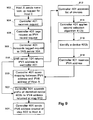
- a flow chart for the translator 400 managing communications initiated by a host C in an IPv4 network (to communicate with a host A) is shown in Figures 6 - 8
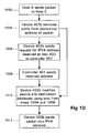
- a flow chart for the translator managing communications initiated by a host A in an IPv6 network (to communicate with a host C) is shown in Figures 9 - 11 .
- Figures 6 and 9 each show a main loop, on the left hand side of the respective flow charts, representing processes carried out in respect of incoming initiating requests. On the right hand side of the respective flow charts there is a sub-loop, which represents processes carried out between the controller 401 and devices 403 i .
- host C in an IPv4 network sends 602 a name lookup request for host A in the IPv6 network.
- This request is received 604 by the controller 401, which tags 606 the request as an IPv6 record request, by modifying the request to a "AAAA" record request, and forwards 608 the tagged request to the DNS server 106.
- the DNS server 106 replies 610, returning an IPv6 network address to the controller 401.
- the controller 401 then tries to identify a device 403 a for mediating communications. This process is shown in the loop on the right hand side of Figure 6 and comprises the following steps: the controller 401 accesses 612 a list of devices 403 i that, for each device 403 i , details loading on the device and IP addresses accessible to that device. Such a list can be stored in memory, as described above. The controller 401 then applies 614 a selection algorithm 412, such as the one described above, to the list in order to identify a device for the current request. Once a device 403 a has been identified 616, an IPv4 address available to that device 403 a is selected and returned 618 to the controller 401. (In addition to, or in place of, the automatic polling of devices 403 i described above, the process 411 may automatically be invoked each time a device is so identified).
- the controller assigns 620 the IPv4 address returned at step 618 to the IPv6 address returned at step 610 and saves a mapping between the two.
- the assigned IPv4 address is then sent 622 to host C.
- host C typically, a number of IP addresses that are available to a device will be pre-assigned to an interface of that device (in a manner known to those skilled in the art), so that a single interface effectively has a plurality of IP addresses.
- the packet will be routed to the corresponding interface of the device 403 a .
- FIG. 7 shows the scenario of host C sending 702 a packet to host A: the packet has a destination address set to the assigned IPv4 address and source address set to the IPv4 address of host C.
- the assigned address is routable to the identified device 403 a (as described in the paragraph above) the packet will arrive at the device 403 a , whereupon the device 403 a sends 704 a request to the controller 401 for the IPv6 address corresponding to the destination address of the packet (which is the IPv4 address assigned at step 620).
- the controller 401 performs 706 a lookup of its stored mappings and transmits 708 the returned IPv6 address to the device 403 a .
- the device 403 a is in receipt of all of the information required to enable it to autonomously mediate further communications between hosts A and host C.
- the device 403 a modifies 710 the source and destination addresses of the packet sent by host C, expanding the source address to include the IPv6 prefix of the device 403 a together with the IPv4 address of the host C (as described above), and setting the destination address to the returned IPv6 address.
- the device 403 a then sends 712 the packet into the IPv6 network for receipt by host A.
- host A sends 802 one or more packets having as destination address the IPv6 prefix of the device 403 a together with the IPv4 address of the host C and as source address its own IPv6 address (which is of course the IPv6 address returned at step 610).
- the device 403 a receives 804 the, or each packet, and queries 806 the controller 401 for an IPv4 address corresponding to the IPv6 source address of the incoming packet.
- the controller 401 returns 808 the corresponding IPv4 address, which is the assigned IPv4 address (from step 620), to the device 403 a , whereupon the source address of the or each incoming packet is replaced 810 with the assigned IPv4 address.
- the device 403 a modifies 812 the destination address, removing the IPv6 prefix of the device 403 a to leave the IPv4 address of host C.
- the device 403 a sends 814 the, or each packet, into the IPv4 network.
- host A in an IPv6 network sends 902 a name lookup request for host C in the IPv4 network.
- This request is received 904 by the controller 401, which tags 906 the request as an IPv4 record request, by modifying the request to a "A" record request, and forwards 908 the tagged request to the IPv4 DNS server 104.
- the DNS server 104 replies 910, returning an IPv4 network address to the controller 401.
- the controller 401 then tries to identify a device 403 b for mediating communications. This process is shown in the loop on the right hand side of Figure 9 and comprises the following steps: the controller 401 accesses 912 the list of devices described above, and applies 914 a selection algorithm 412 to the devices on the list in order to identify a device for the current request. Once a device 403 b has been identified 916, the controller 401 reserves 918 an IPv4 address from the pool 405 accessible to the identified device 403 b . The controller 401 then saves 920 a mapping between the reserved IPv4 address and the IPv6 address of host A. Finally the controller 401 appends 922 a prefix identifier of the identified device 403 b (as described above) to the IPv4 address returned at step 910, and sends 924 this to host A.
- the device 403 b is in receipt of all of the information required to enable it to autonomously mediate further communications between hosts A and host C.
- Figure 10 shows the scenario of host A sending 1002 a packet to host C: the packet has a destination address set to the IPv6 address sent at step 924. As this address is globally routable to the identified device 403 b (as described above) the packet will arrive at the device 403 b , whereupon the device 403 b removes 1004 the prefix from the destination address, leaving the IPv4 address of host C.
- the device 403 b sends 1006 a request for the IPv4 address reserved at step 922, whereupon the controller 401 sends 1008 the reserved address.
- the device 403 b modifies 1010 the source and destination addresses of the packet sent by host A, setting the source address to the IPv4 address of the host C, and setting the destination address to the reserved IPv4 address.
- the device 403 b then sends 1012 the packet into the IPv4 network for receipt by host C.
- such a response may comprise one or more packets having as destination address the reserved IPv4 address and as source address its own IPv4 address.
- the device 403 b receives 1104 the, or each packet, and queries 1106 the controller 401 for an IPv6 address corresponding to the destination address of the packet.
- the controller 401 performs a lookup of its stored mappings and returns 1108 an IPv6 address, which is the IPv6 address of host A.
- the device 403 b adds 1110 its prefix to the source address of the packet (IPv4 address of host C) to form an IPv6 address, as described above, and the destination address of the packet is replaced 1112 with the IPv6 address returned at step 1108 (i.e. the IPv6 address of originating host A). Finally the device 403 b sends 1114 the packet into the IPv6 network.
- the second embodiment includes all of the features described in respect of the first embodiment, but instead of the address mappings being stored on the controller 401, the mappings are stored on a remote database, or similar, that is accessible to both the controller 401 and the devices 403 i . Thus in this embodiment the devices 403 i do not have to communicate with the controller 401 at all once the initial address assignment has been established.
- the third embodiment includes all of the features described in respect of the first embodiment, but the devices 403 a cache addresses in memory for a predetermined period.
- This embodiment would be particularly suitable for the scenario shown in Figures 6 - 11 , where a host in an IPv4 network initiates communication, and where an intense period of communication is in progress between hosts A and C. If the device 403 a caches mapping information locally, the device 403 a does not have to continually request address mapping information from the controller. This therefore keeps communication between A and C wholly independent of the controller 401, minimizes network traffic and allows communications dependent on address translation to progress faster than in the other embodiments.
- the fourth embodiment includes all of the features described in respect of the first embodiment, but the mappings are stored in the address pool 405, rather than in the controller 401. As for the second and third embodiments, the devices 403 i do not have to communicate with the controller 401 at all once the initial address assignment has been established.
- the fifth embodiment includes all of the features described in respect of the first embodiment, but the allocation of IPv4 addresses from the address pool 405 is managed by the controller 401, rather than by the devices 403 i .
- the first and second selection algorithms do not include reviewing IP address availability when identifying a device 403 i .
- the address pool 405 could be stored on a Dynamic Host Configuration Protocol (DHCP) server, so that the controller 401 requests IPv4 addresses in accordance with DHCP.
- DHCP Dynamic Host Configuration Protocol
- (where allocation of IPv4 addresses is managed by the controller 401) then allocated addresses must be configured into the IPv4 interface of the identified device 403 i . i.e. an address is chosen from the address pool 405, which is then given it to the identified device 403 i .
- This embodiment could be used in conjunction with either of the second, third or fourth embodiments.
- the sixth embodiment can be used in conjunction with any of the above embodiments.
- This embodiment is concerned with resilience issues relating to the controller 401: in the event that the controller 401 is operationally inactive or the loading on the controller becomes unacceptably high, some kind of "back-up" system is required.
- the sixth embodiment provides a second, or a mirror, controller, which monitors the operational status and loading on the controller 401 in accordance with predetermined criteria.
- the mirror controller detects that the controller 401 fails to satisfy one or more of the criteria, it either switches all control over to the mirror controller, which thereafter services the requests in the manner described above, or it balances control between the mirror controller and the controller 401.
- an alert is sent to the party operating the translator 400.
- a cascaded arrangement of controllers 401 i could be a preferred arrangement, in view of the fact that the number of requests is expected to scale with the introduction of IPv6 networks.
- the translator 400 could include a plurality of active controllers without requiring any significant changes to the above-described embodiments.
- the DNS servers 104, 106 could be configured to forward requests to a next available controller in the event that a given controller fails (One of the features of a DNS server is that it can be configured to forward requests for certain domain names to more than one other DNS server. This feature could be employed in connection with the controllers, to achieve the above-described effect).
- Some of these methods are naturally scalable - such as SIIT, because it is a stateless mechanism and BIS, because address translation takes place in a host.
- SIIT stateless mechanism
- BIS address translation takes place in a host.
- other methods such as DSTM, suffer from scalability problems similar to those identified for NAT-PT.
- Embodiments of the invention could thus be integrated with features of the DSTM architecture in order to improve their scalability.
- a dual stack host tunnels IPv4 packets over an IPv6 network to a DSTM border router at the IPv4/IPv6 boundary, where the packets are subsequently un-encapsulated into IPv4 packets.
- the dual stack host is dynamically assigned an IPv4 address by a DHCP server (to be used as source address for any packets sent into the IPv4 network).
- the DHCP server tells the dual stack host of the IPv6 address of the border router (termed "tunnel endpoint").
- the DHCP server assigns an IPv6 tunnel endpoint address (border router) according to the loading etc. on available border routers.
- the controller 401 would co-operate with the DHCP server and the devices 403 i would be DSTM border routers.
Landscapes
- Engineering & Computer Science (AREA)
- Computer Networks & Wireless Communication (AREA)
- Signal Processing (AREA)
- Computer Security & Cryptography (AREA)
- Data Exchanges In Wide-Area Networks (AREA)
- Memory System Of A Hierarchy Structure (AREA)
- Machine Translation (AREA)
- Communication Control (AREA)
Abstract
Description
- This invention relates to an address translator, and is suitable particularly, but not exclusively, for address translation between different networks.
- Currently all commercial Internet Protocol (IP) networks are IPv4 networks; however, at some point in the future, commercial IP networks will be IPv6 networks. In the meantime there will be a transitory period, during which commercial IP networks will comprise a mixture of IPv4 and IPv6 networks. IPv6 is a totally different protocol to IPv4 and is fundamentally incompatible with IPv4. Therefore, during the transitory period at least, network devices and/or networks will require mechanisms to enable a node and/or host in an IPv4 network, having an IPv4 address, to communicate with a node and/or host in an IPv6 network, having an IPv6 address.
- Several migration mechanisms have been developed; see for example a document published in November 2000 by the Internet Engineering Task Force (IETF) and available from the IETF at http://www.ietf.org/internet-drafts/draft-ietf-ngtrans-introduction-to-ipv6-transition-05.txt, entitled "An Overview of the Introduction of IPv6 in the Internet", authors: W. Biemolt et al, IETF Status: Draft working towards Informational RFC. Essentially these methods can be categorized as either "aggressive, short term" methods or "conservative, long term" methods.
- A problem with at least some of known migration methods is that they have been designed and operated in a test environment, and have not been subjected to the volume of traffic experienced in commercial IP networks. There has therefore been little work carried out on designing migration methods that are commercially scalable and robust. This could be a serious problem, given that the transition between IPv4 and IPv6 is expected to be long, and the volume of IP traffic is continually increasing.
- In the following description, the terms "host", "network device", "pool of addresses" and "node" are used and are defined as follows:
- "node": any equipment that is attached to a network, including routers, switches, repeaters, hubs, clients, servers; the terms "node", "device" and "network device" are used interchangeably;
- "host": equipment for processing applications, which equipment could be either server or client, and may also include a firewall machine; and
- "pool of addresses": a group of addresses available for a purpose; the addresses could include IPv4 addresses that are globally unique, or addresses that are private within a network, e.g. a VLAN.
- According to a first aspect of the invention there is provided apparatus for providing communication between a network device in a first network and a network device in a second network, where the first network operates in accordance with a first communication protocol and the second network operates in accordance with a second communication protocol. The apparatus comprises
- (i) first means for assigning an alias to a target network device in the first network, the alias being compatible with the communication protocol of the second network;
- (ii) second means for translating said assigned alias to an address for the target network device, said translated address being compatible with the communication protocol of the first network,
- Particularly advantageous embodiments of the invention are applied between IPv4 and IPv6 networks, so that the first network is a IPv4 network and the second network is a IPv6 network.
- Preferably the alias comprises a network address, and when the communication is being sent into an IPv6 network, the network address includes an identifier representative of the second means.
- Conveniently the second means comprises a plurality of further devices. Thus, upon assignment of alias to the target network device, the first means effectively causes subsequent communications to occur via one of a plurality of further devices. Having a plurality of devices advantageously introduces resilience, scalability and efficient management of network loading.
- Advantageously the or each further device has access to one or more groups of aliases, and each group can be stored in a store. Alternatively, two or more groups can be stored in a store.
- Preferably embodiments include selecting means for selecting one of the plurality of further devices in accordance with predetermined criteria, such as device characteristics. Advantageously the selecting means is operable to monitor the device characteristics, so that selection of a device is based on current device performance. Monitored device characteristics include at least one of operational status of device, loading on device, and/or aliases available to the device.
- In preferred embodiments, the selecting means is in operative association with the first means, so that the first means is operable to retrieve an alias available to the further device, which retrieved alias is the assigned alias.
- Conveniently embodiments include a mapping store for storing mappings between the assigned alias and the network device assigned to the alias. The mapping store can be managed by the first means, a database, or by the further device. The selection of manager of the mapping stored is typically subject to criteria such as network traffic, ownership of network devices and transmission paths.
- According to a second aspect of the present invention there is provided a method of providing communication between a network device in a first network and a network device in a second network corresponding to the apparatus described above.
- Further aspects, features and advantages of the present invention will be apparent from the following description of preferred embodiments of the invention, which refer to the accompanying drawings, in which
-
Figure 1 is a schematic diagram showing a first and a second network and known means facilitating communicating between the first and second networks; -
Figure 2 is a flow diagram showing steps carried out by a known address translation process when setting up communications between hosts located in the first and second networks ofFigure 1 ; -
Figure 3 is a flow diagram showing steps carried out by a known address translation process when data is sent from a host located in the first network to a host located in the second network ofFigure 1 ; -
Figure 4 is a schematic diagram showing an address translator according to an embodiment of the present invention; -
Figure 5a is a schematic diagram showing a configuration of address pool comprising part of the address translator shown inFigure 4 , -
Figure 5b is a schematic diagram showing an alternative configuration of address pool comprising part of the address translator shown inFigure 4 , -
Figure 5c is a schematic diagram showing yet another possible configuration of address pool comprising part of the address translator shown inFigure 4 , -
Figure 6 is a flow diagram showing steps carried out by an embodiment of the address translator shown inFigure 4 , when setting up communications instigated by a host in the first network; -
Figure 7 is a flow diagram showing steps carried out by an embodiment of the address translator shown inFigure 4 , when data is sent from the instigating host ofFigure 6 to a host in the second network; -
Figure 8 is a flow diagram showing steps carried out by an embodiment of the address translator shown inFigure 4 , when data is returned from the host in the second network; -
Figure 9 is a flow diagram showing steps carried out by an embodiment of the address translator shown inFigure 4 , when setting up communications instigated by a host in the second network; -
Figure 10 is a flow diagram showing steps carried out by an embodiment of the address translator shown inFigure 4 , when data is sent from the instigating host ofFigure 9 to a host in the first network; and -
Figure 11 is a flow diagram showing steps carried out by an embodiment of the address translator shown inFigure 4 , when data is returned from the host in the first network. - Embodiments of the invention are concerned with issues relating to migration from IPv4 to IPv6 networks. Specifically, embodiments of the invention are concerned with scalability aspects of migration methods; as stated above, almost all of the IPv6 networks currently in operation are "test" networks and are not subject to the volume of IP traffic passing through commercial IP networks. Thus the performance of the migration methods in a commercial environment may be unacceptably low.
- One embodiment of the invention is concerned with the Network Address Translator - Protocol Translator (NAT-PT) method, which is documented by the IETF in Request for Comments" RFC2766, available from the IETF at http://www.ietf.org/rfc/rfc2766.txt. NAT-PT is a mechanism that translates both the IP header and the IP addresses from IPv6 to IPv4, and vice versa. With NAT-PT explicit mappings are maintained between arbitrary IPv4 and IPv6 addresses, so that, when converting addresses, NAT-PT consults a pre-configured table to determine the corresponding address to use with the other protocol. As documented in the Introduction section of RFC2766, with NAT-PT, packets that are part of a session between an IPv4 host and an IPv6 host MUST go via the same NAT-PT entity, because address mappings are kept within that NAT-PT and are not shared. This is a consequence of the translation mechanism of NAT-PT: NAT-PT is a stateful translation process, meaning that there is specific information that must be retained in order for each individual session to be translated.
- Thus address translation is performed by aliasing an IPv6 address with an IPv4 address in much the same way as is done with a conventional Network Address Translation (NAT) device. Some NAT-PT implementations include a DNS Application Level Gateway (DNS_ALG), which translates DNS requests and responses.
-
Figure 1 shows a conventional implementation of NAT-PT in operation between a first network NW1, which may be an IPv4 network and a second network NW2, which may be an IPv6 network. The implementation includes asingle translator 101, which comprisesprocesses 102 that manage assignment of IPv6/v4 addresses.Such processes 102 include the DNS application level gateway. In addition thetranslator 101 has access to apool 103 of IPv4 addresses, which is used for assignment to IPv6 nodes.Figure 1 additionally shows twoDNS servers - The
translator 101 is typically located on a border router, referred to as an ingress interface with respect to the IPv6 network NW2. In general - Conventional operation of this known NAT-PT implementation is shown in
Figure 2 . In a typical scenario, host C in the IPv4 network sends 202 a name lookup request for host A in the IPv6 network. This lookup request is termed an "A" type DNS request. This request is received 204 by thetranslator 101, which tags 206 the request as an IPv6 record request, so that the request becomes an "AAAA" type DNS request, and forwards 208 the tagged request to theDNS server 106. - The
DNS server 106 replies 210, returning an IPv6 network address to thetranslator 101, which, in co-operation with theprocesses 102, assigns 212 an IPv4 address from the pool of addresses to the returned IPv6 address. Thetranslator 101stores 214 the mapping between the assigned IPv4 address and the returned IPv6 address, and forwards 216 the assigned IPv4 address to the requesting host C. - In subsequent communications between hosts C and A, and as shown in
Figure 3 , host C sets 302 the destination address to be the assigned IPv4 address for outgoing packets, and sends 304 the packets to the assigned IPv4 address of Host A, and conventional IP routing ensures that the packet routes to thetranslator 101. Thetranslator 101 then looks up 306 the mapping between assigned IPv4 address and IPv6 address to retrieve the IPv6 address of host A, and makes this 308 the destination address of the packet. - For the packets to be routed from the
translator 101 to host A, thetranslator 101 has to modify the source address of the packet, which is the IPv4 address of node C, into IPv6 format. This involves expanding 310 the IPv4 address of host C with a prefix that is representative of thetranslator 101. As is well known, an IPv4 address is 32bits long, whereas an IPv6 address is 128bits long. As stated above, an IPv6 host cannot interpret an IPv4 address, and vice-versa - because of the differences in address length. Thus when an IPv4 packet arrives at the translator 101 a 96bit prefix, which is indicative of thetranslator 101, is added to the source address of the packet (32bits) to make an IPv6 address (128bits). Packets sent to this IPv6 address will then be routed to thetranslator 101. [For example an IPv4 source address 10.10.10.10 arriving at thetranslator 101 could be given the prefix 2001:618:1:2:: so that the source IPv4 host has the following address in the IPv6 world: 2001:618:1:2::10.10.10.10. An IPv6 packet sent to this address would go totranslator 101 because the prefix 2001:628:1:2:: routes to thetranslator 101.] - The
translator 101 then sends 312 the packet, using the expanded IPv6 address. All subsequent communications between host A and host C can make use of the mappings stored in thetranslator 101. - Communications initiated by host A, in the IPv6 network, involve similar address assignment; for a working example the reader is referred to the RFC detailed above.
- From the above it can be seen that, once IPv6 addresses have been assigned, the
translator 101 performs translation of packets as they pass between hosts (C) in the IPv4 network and hosts (A) in the IPv6 network, thus acting as a medium for all communication between said hosts A, C. A problem with this configuration is that centralized address assignment and communications processing could present scalability problems when IPv6 networks become mainstream. - The essence of embodiments of the invention is that the functionality of initial address assignment (
Figure 2 ) is separated from subsequent events that make use of the assigned addresses (e.g. packet encapsulation as packets pass from host A to host C, as shown inFigure 3 ). This is a particularly unexpected development of the NAT-PT method described in RFC2766: the RFC mandates that, because NAT-PT is stateful, address assignment and allocation should be carried out on one and the same device - i.e. that they are inseparable. - In one embodiment of the invention, and as shown in
Figure 4 , thetranslator 400 essentially comprises two components: acontroller 401 and a plurality ofdevices controller 401, which polls the devices 403i in order to identify one that has capacity to service the request. A device so identified thereafter deals with all subsequent communication between hosts in IPv6 and IPv4, and the subsequent communication is therefore independent of the controller operations. The configuration and functionality of these components is described in more detail below. - Thus in embodiments of the invention, address assignment events are separated from subsequent communication events between hosts in IPv4 and IPv6 networks (e.g. translating packets using the assigned addresses). In addition, the
controller 401 can select from a plurality of devices for address assignment. - There are several advantages associated with the embodiments:
- o Firstly devices are passive in the address assignment phase (
Figure 2 ), which means that if a device fails it won't affect servicing of new requests (thecontroller 401 can select another device, for example). - Secondly the
translator 400 is scalable, as devices can easily be added in accordance with demand. - o Thirdly, communication between devices in IPv4 and IPv6 networks can continue independently of address assignment, so that (i) failure of
controller 401 due to address assignment problems does not affect communications that have already been established between hosts in IPv4 and IPv6 networks; (ii) network problems corresponding to communications between IPv4 and IPv6 hosts do not affect the controller; and (iii) the controller does not have to account for, or schedule, subsequent communication events. - o Fourthly, as IPv6 begins to outgrow IPv4 then devices can be de-commissioned as required, again without major translation service disruption.
- o Fifthly, for an IP network provider to deploy an IPv6 network with "IPv6-only" services, it will be necessary to provide some kind of translation facility so that both IPv4 network users can access the IPv6 services and IPv6 users can access existing IPv4 based services. The embodiments presented herein allow a commercial service provider the ability to dynamically scale the address translation service according to the dimensions of the IPv6 network.
- Referring back to
Figure 4 , the configuration of thetranslator 400 will now be described in more detail. - The
controller 401 receives DNS requests initiated by hosts in either the IPv4 or the IPv6 networks, and manages DNS lookups, in the manner described above, in respect of the requests. Having received a returned IPvn address from arespective DNS server controller 401 then identifies a device 403i that will mediate for subsequent communications between the requesting host (in the example above, host C) and the destination host (in the example above, host A). Each device has a globally routable prefix (i.e. a prefix that is appended to destination addresses of packets destined for the device), which, when appended to an IPv4 address, enables packets to reach the device (as described above). - In one embodiment identification of a device 403i comprises determining whether the device 403i is up and running. In addition the
controller 401 identifies whether there are any free addresses available to the device 403i, and the current loading on, or the number of communications that are currently being handled by, a device. Conveniently thecontroller 401 may run aprogram 411, which polls each device 403i at predetermined intervals to determine current loading, operational status and IP addresses accessible to that device. Theprogram 411 gathers the loading and address availability data from the devices 403i, and stores it, for example as a list in memory. Thecontroller 401 may run theprogram 411 at predetermined intervals, for example every second, or as frequently as required to capture changes to the devices 403i. - The
controller 401 may also run selection algorithms for selecting a device 403a from the list. For example, atypical selection algorithm 412 searches the list for an operational device that has access to at least one free IPv4 address and that has a loading below a predetermined threshold. If more than one device satisfies these criteria, then the device with lowest loading is selected. Many variations on this example are possible, and would be apparent to the skilled person. - In one embodiment each device 403i may be a conventional router, so that the
controller 401 can derive the loading on a device 403a by issuing Simple Network Management Protocol (SNMP) messages to a Management Information Base (MIB) that is maintained on the router. SNMP is part of the known TCP/IP network software, and MIB, or Management Information Base, is a standard specifying the data items that a host, router or switch must keep, together with the operations allowed on each. SNMP is the protocol that enables information to be extracted from a MIB, and is known to those skilled in the art. For further details see Request for Comments (RFC) 2037/2737, Entity MIB, McCloghnie et al 1996/1999, published by the Internet Engineering Task Force (IETF) (available from http://www.ietf.org), or Understanding SNMP MIBs by David Perkins, Evan McGinnis. Prentice Hall, 1st edition (December 3, 1996). - In one of the embodiments each of the devices 403i has access to a
pool 405 of IPv4 addresses, and the availability, to any single device 403a of IP addresses, is recorded on a respective device 403. Thecontroller 405 could therefore determine address availability per device 403 by reviewing the record of address availability thereon. The skilled person would realize that such a record does not need to be stored on the devices themselves, but could be held centrally, e.g. in a database. - The
pool 405 can either be a central pool, as is shown inFigure 4 , and accessible by all of the devices 403i, or can comprise a plurality of pools, each accessible to a limited number of the devices 403i. For example, there may be onepool 405 per device 403i, as shown inFigure 5a , or there may be onepool 405 per n devices 403i, as shown inFigures 5b and 5c . - Essentially the
controller 401 may comprise one or more programs running on a processor, such as a conventional client or server computer. Alternatively thecontroller 401 could run on a router. In either configuration, thecontroller 401 could connect to each of the devices 403i via dedicated links or via the Internet; if security were a consideration, dedicated links would be more suitable. As an alternative, a security protocol, such as IPsec, which is a mandatory part of IPv6, could be used for communications betweencontroller 401 and devices 403i. The programs can include socket processes that listen for incoming DNS lookup requests and listen for requests from devices 403i. - In preferred embodiments the
controller 401 processes incoming requests on a FIFO (First-in, First-out) basis - i.e. thecontroller 401 implements a queuing discipline in which entities (here requests, incoming packets) are stored in a queue (or in the stack) and are serviced in the same order in which they arrive. As an alternative, thecontroller 401 could process requests in accordance with LIFO (last-in, first-out), where the most recent request is handled next and the oldest request doesn't get handled until it is the only remaining request on the queue (or in the stack). - Other scheduling policies are possible, e.g. when the
controller 401 is subject to constraints; a suitable scheduling policy could utilise some sort of heuristic method (or combination of heuristic methods) in an attempt to schedule the requests so as to satisfy the constraint criteria. As a further alternative, the scheduling policy could make use of Quality of Service information included in IPv6 headers: certain bits in the IP header indicate the priority of the request, and thecontroller 401 could include means for examining these bits (not shown). Thecontroller 401 could have a plurality of queues, each corresponding to a different priority level, which thecontroller 401 services on, e.g. a sequential basis. - A flow chart for the
translator 400 managing communications initiated by a host C in an IPv4 network (to communicate with a host A) is shown inFigures 6 - 8 , and a flow chart for the translator managing communications initiated by a host A in an IPv6 network (to communicate with a host C) is shown inFigures 9 - 11 . -
Figures 6 and9 each show a main loop, on the left hand side of the respective flow charts, representing processes carried out in respect of incoming initiating requests. On the right hand side of the respective flow charts there is a sub-loop, which represents processes carried out between thecontroller 401 and devices 403i. - Considering firstly the case shown in
Figure 6 , host C in an IPv4 network sends 602 a name lookup request for host A in the IPv6 network. This request is received 604 by thecontroller 401, which tags 606 the request as an IPv6 record request, by modifying the request to a "AAAA" record request, and forwards 608 the tagged request to theDNS server 106. TheDNS server 106 replies 610, returning an IPv6 network address to thecontroller 401. - The
controller 401 then tries to identify a device 403a for mediating communications. This process is shown in the loop on the right hand side ofFigure 6 and comprises the following steps: thecontroller 401 accesses 612 a list of devices 403i that, for each device 403i, details loading on the device and IP addresses accessible to that device. Such a list can be stored in memory, as described above. Thecontroller 401 then applies 614 aselection algorithm 412, such as the one described above, to the list in order to identify a device for the current request. Once a device 403a has been identified 616, an IPv4 address available to that device 403a is selected and returned 618 to thecontroller 401. (In addition to, or in place of, the automatic polling of devices 403i described above, theprocess 411 may automatically be invoked each time a device is so identified). - The controller assigns 620 the IPv4 address returned at
step 618 to the IPv6 address returned atstep 610 and saves a mapping between the two. The assigned IPv4 address is then sent 622 to host C. Typically, a number of IP addresses that are available to a device will be pre-assigned to an interface of that device (in a manner known to those skilled in the art), so that a single interface effectively has a plurality of IP addresses. Thus when a packet is sent from host C bearing a destination address of the assigned IPv4 address, the packet will be routed to the corresponding interface of the device 403a. - At this point host C has an IPv4 address for host A, which it can use to route packets to host A.
Figure 7 shows the scenario of host C sending 702 a packet to host A: the packet has a destination address set to the assigned IPv4 address and source address set to the IPv4 address of host C. As the assigned address is routable to the identified device 403a (as described in the paragraph above) the packet will arrive at the device 403a, whereupon the device 403a sends 704 a request to thecontroller 401 for the IPv6 address corresponding to the destination address of the packet (which is the IPv4 address assigned at step 620). Thecontroller 401 performs 706 a lookup of its stored mappings and transmits 708 the returned IPv6 address to the device 403a. At this point the device 403a is in receipt of all of the information required to enable it to autonomously mediate further communications between hosts A and host C. - The device 403a then modifies 710 the source and destination addresses of the packet sent by host C, expanding the source address to include the IPv6 prefix of the device 403a together with the IPv4 address of the host C (as described above), and setting the destination address to the returned IPv6 address. The device 403a then sends 712 the packet into the IPv6 network for receipt by host A.
- Referring to
Figure 8 , if host A sends a response to host C, host A sends 802 one or more packets having as destination address the IPv6 prefix of the device 403a together with the IPv4 address of the host C and as source address its own IPv6 address (which is of course the IPv6 address returned at step 610). The device 403a receives 804 the, or each packet, and queries 806 thecontroller 401 for an IPv4 address corresponding to the IPv6 source address of the incoming packet. - The
controller 401 returns 808 the corresponding IPv4 address, which is the assigned IPv4 address (from step 620), to the device 403a, whereupon the source address of the or each incoming packet is replaced 810 with the assigned IPv4 address. In addition the device 403a modifies 812 the destination address, removing the IPv6 prefix of the device 403a to leave the IPv4 address of host C. Finally the device 403a sends 814 the, or each packet, into the IPv4 network. - Considering secondly the case shown in
Figure 9 , host A in an IPv6 network sends 902 a name lookup request for host C in the IPv4 network. This request is received 904 by thecontroller 401, which tags 906 the request as an IPv4 record request, by modifying the request to a "A" record request, and forwards 908 the tagged request to theIPv4 DNS server 104. TheDNS server 104 replies 910, returning an IPv4 network address to thecontroller 401. - The
controller 401 then tries to identify a device 403b for mediating communications. This process is shown in the loop on the right hand side ofFigure 9 and comprises the following steps: thecontroller 401 accesses 912 the list of devices described above, and applies 914 aselection algorithm 412 to the devices on the list in order to identify a device for the current request. Once a device 403b has been identified 916, thecontroller 401reserves 918 an IPv4 address from thepool 405 accessible to the identified device 403b. Thecontroller 401 then saves 920 a mapping between the reserved IPv4 address and the IPv6 address of host A. Finally thecontroller 401 appends 922 a prefix identifier of the identified device 403b (as described above) to the IPv4 address returned atstep 910, and sends 924 this to host A. - At this point the device 403b is in receipt of all of the information required to enable it to autonomously mediate further communications between hosts A and host C.
-
Figure 10 shows the scenario of host A sending 1002 a packet to host C: the packet has a destination address set to the IPv6 address sent atstep 924. As this address is globally routable to the identified device 403b (as described above) the packet will arrive at the device 403b, whereupon the device 403b removes 1004 the prefix from the destination address, leaving the IPv4 address of host C. - The device 403b sends 1006 a request for the IPv4 address reserved at
step 922, whereupon thecontroller 401 sends 1008 the reserved address. The device 403b modifies 1010 the source and destination addresses of the packet sent by host A, setting the source address to the IPv4 address of the host C, and setting the destination address to the reserved IPv4 address. The device 403b then sends 1012 the packet into the IPv4 network for receipt by host C. - Referring to
Figure 11 , if host C sends 1102 a response to host A, such a response may comprise one or more packets having as destination address the reserved IPv4 address and as source address its own IPv4 address. The device 403b receives 1104 the, or each packet, and queries 1106 thecontroller 401 for an IPv6 address corresponding to the destination address of the packet. Thecontroller 401 performs a lookup of its stored mappings and returns 1108 an IPv6 address, which is the IPv6 address of host A. - The device 403b adds 1110 its prefix to the source address of the packet (IPv4 address of host C) to form an IPv6 address, as described above, and the destination address of the packet is replaced 1112 with the IPv6 address returned at step 1108 (i.e. the IPv6 address of originating host A). Finally the device 403b sends 1114 the packet into the IPv6 network.
- The second embodiment includes all of the features described in respect of the first embodiment, but instead of the address mappings being stored on the
controller 401, the mappings are stored on a remote database, or similar, that is accessible to both thecontroller 401 and the devices 403i. Thus in this embodiment the devices 403i do not have to communicate with thecontroller 401 at all once the initial address assignment has been established. - The third embodiment includes all of the features described in respect of the first embodiment, but the devices 403a cache addresses in memory for a predetermined period. This embodiment would be particularly suitable for the scenario shown in
Figures 6 - 11 , where a host in an IPv4 network initiates communication, and where an intense period of communication is in progress between hosts A and C. If the device 403a caches mapping information locally, the device 403a does not have to continually request address mapping information from the controller. This therefore keeps communication between A and C wholly independent of thecontroller 401, minimizes network traffic and allows communications dependent on address translation to progress faster than in the other embodiments. - The fourth embodiment includes all of the features described in respect of the first embodiment, but the mappings are stored in the
address pool 405, rather than in thecontroller 401. As for the second and third embodiments, the devices 403i do not have to communicate with thecontroller 401 at all once the initial address assignment has been established. - The fifth embodiment includes all of the features described in respect of the first embodiment, but the allocation of IPv4 addresses from the
address pool 405 is managed by thecontroller 401, rather than by the devices 403i. In such a situation the first and second selection algorithms do not include reviewing IP address availability when identifying a device 403i. In this embodiment theaddress pool 405 could be stored on a Dynamic Host Configuration Protocol (DHCP) server, so that thecontroller 401 requests IPv4 addresses in accordance with DHCP. In this situation, (where allocation of IPv4 addresses is managed by the controller 401) then allocated addresses must be configured into the IPv4 interface of the identified device 403i. i.e. an address is chosen from theaddress pool 405, which is then given it to the identified device 403i. - This embodiment could be used in conjunction with either of the second, third or fourth embodiments.
- The sixth embodiment can be used in conjunction with any of the above embodiments. This embodiment is concerned with resilience issues relating to the controller 401: in the event that the
controller 401 is operationally inactive or the loading on the controller becomes unacceptably high, some kind of "back-up" system is required. - The sixth embodiment provides a second, or a mirror, controller, which monitors the operational status and loading on the
controller 401 in accordance with predetermined criteria. In the event that the mirror controller detects that thecontroller 401 fails to satisfy one or more of the criteria, it either switches all control over to the mirror controller, which thereafter services the requests in the manner described above, or it balances control between the mirror controller and thecontroller 401. Preferably an alert is sent to the party operating thetranslator 400. - A cascaded arrangement of
controllers 401i could be a preferred arrangement, in view of the fact that the number of requests is expected to scale with the introduction of IPv6 networks. As thecontroller 401 allocates sessions to the devices 403i dynamically, thetranslator 400 could include a plurality of active controllers without requiring any significant changes to the above-described embodiments. Furthermore, theDNS servers - As disclosed in the document published by the IETF, referred to above (available at http://www.ietf.org/internet-drafts/draft-ietf-ngtrans-introduction-to-ipv6-transition-05.txt), other migration methods include:
- Automatic Tunnels
- Configured Tunnels
- Tunnel Broker
- 6over4
- 6to4
- Dual stack transition mechanism (DSTM)
- Stateless IP/ICMP Translation Algorithm (SIIT)
- Bump-In-the-Stack" Technique (BIS)
- STOCKS64
- Some of these methods are naturally scalable - such as SIIT, because it is a stateless mechanism and BIS, because address translation takes place in a host. However, other methods, such as DSTM, suffer from scalability problems similar to those identified for NAT-PT. Embodiments of the invention could thus be integrated with features of the DSTM architecture in order to improve their scalability.
- With DSTM, and as is known to those skilled in the art, a dual stack host tunnels IPv4 packets over an IPv6 network to a DSTM border router at the IPv4/IPv6 boundary, where the packets are subsequently un-encapsulated into IPv4 packets. The dual stack host is dynamically assigned an IPv4 address by a DHCP server (to be used as source address for any packets sent into the IPv4 network). In addition, the DHCP server tells the dual stack host of the IPv6 address of the border router (termed "tunnel endpoint"). Embodiments of the present invention could be integrated with the DSTM method so that the DHCP server assigns an IPv6 tunnel endpoint address (border router) according to the loading etc. on available border routers.
- Thus, in terms of the elements of the embodiments presented above, the
controller 401 would co-operate with the DHCP server and the devices 403i would be DSTM border routers.
Claims (19)
- Apparatus for providing communication between a network device (C) in a first network (NW1) and a network device (A) in a second network (NW2), the first network operating in accordance with a first communication protocol and the second network operating in accordance with a second communication protocol, the apparatus comprising(i) first means (401) for assigning an alias to a target network device in the first network, the alias being compatible with the communication protocol of the second network;(ii) second means (403) for translating said assigned alias to an address for the target network device, said translated address being compatible with the communication protocol of the first network,wherein the first means (401) and the second means (403) are separately addressable in one or both of said networks, and said assigned alias corresponds to an address of the second means (403), such that, when a network device (C) in the second network sends one or more communication(s) using an address comprising the assigned alias, the or each communication is routed to the second means (403), whereupon the second means translates the alias into the address of the target network device (A) in the first network and sends the communication(s) into the first network.
- Apparatus according to claim 1, wherein the alias comprises a network address.
- Apparatus according to claim 2, wherein the network address includes an identifier representative of the second means (403).
- Apparatus according to claim 3, wherein the second means comprises a plurality of further devices (403a-403d).
- Apparatus according to claim 4, wherein the or each further device has access to one or more groups of aliases.
- Apparatus according to claim 5, wherein each group is stored in a store (405).
- Apparatus according to claim 5, wherein two or more groups are stored in a store (405).
- Apparatus according to any one of claims 4 to 7, including selecting means (401) for selecting one of the plurality of further devices (403) in accordance with predetermined criteria.
- Apparatus according to claim 8, wherein the predetermined criteria includes device characteristics.
- Apparatus according to claim 9, wherein the selecting means (401) is operable to monitor device characteristics.
- Apparatus according to claim 9 or claim 10, wherein the device characteristics include at least one of operational status of device, loading on device, and/or aliases available to the device.
- Apparatus according to any one of claims 8 to 11, wherein the selecting means is in operative association with the first means.
- Apparatus according to any one of claims 4 to 12, wherein the first means (401) is operable to retrieve an alias available to the further device (403), which retrieved alias is the assigned alias.
- Apparatus according to any one of claims 4 to 13, including a mapping store (405) for storing mappings between the assigned alias and the target network device assigned to the alias.
- Apparatus according to claim 14, wherein the mapping store is managed by the first means (401).
- Apparatus according to claim 14, wherein the mapping store is managed by a database.
- Apparatus according to claim 14, wherein the mapping store is managed by the further device (403).
- A method of providing communication between a network device in a first network and a network device in a second network, the first network operating in accordance with a first communication protocol and the second network operating in accordance with a second communication protocol, the method comprising the steps of:(i) assigning using a first means an alias to a target network device in the first network, the alias being compatible with the communication protocol of the second network; .(ii) translating using a second means said assigned alias to an address for the target network device, said translated address being compatible with the communication protocol of the first network,wherein the first means (401) and the second means (403) are separately addressable in one or both of said networks, and said assigned alias corresponds to an address of the second means (403), such that, when a network device (C) in the second network sends one or more communication(s) using an address comprising the assigned alias, the or each communication is routed to the second means (403), whereupon the second means translates the alias into the address of the target network device (A) in the first network and sends the communication(s) into the first network.
- A method according to claim 18, further including monitoring device characteristics of the or each further devices, and comparing monitored device characteristics with the said predetermined criteria so as to select a said further device.
Priority Applications (1)
| Application Number | Priority Date | Filing Date | Title |
|---|---|---|---|
| EP02706919A EP1366613B1 (en) | 2001-03-08 | 2002-03-05 | Address translator and address translation method |
Applications Claiming Priority (4)
| Application Number | Priority Date | Filing Date | Title |
|---|---|---|---|
| EP01302109 | 2001-03-08 | ||
| EP01302109 | 2001-03-08 | ||
| EP02706919A EP1366613B1 (en) | 2001-03-08 | 2002-03-05 | Address translator and address translation method |
| PCT/GB2002/000970 WO2002073933A1 (en) | 2001-03-08 | 2002-03-05 | Address translator |
Publications (2)
| Publication Number | Publication Date |
|---|---|
| EP1366613A1 EP1366613A1 (en) | 2003-12-03 |
| EP1366613B1 true EP1366613B1 (en) | 2008-09-24 |
Family
ID=8181772
Family Applications (1)
| Application Number | Title | Priority Date | Filing Date |
|---|---|---|---|
| EP02706919A Expired - Lifetime EP1366613B1 (en) | 2001-03-08 | 2002-03-05 | Address translator and address translation method |
Country Status (7)
| Country | Link |
|---|---|
| US (1) | US8046452B2 (en) |
| EP (1) | EP1366613B1 (en) |
| JP (1) | JP4001820B2 (en) |
| AT (1) | ATE409385T1 (en) |
| CA (1) | CA2435985C (en) |
| DE (1) | DE60229042D1 (en) |
| WO (1) | WO2002073933A1 (en) |
Families Citing this family (55)
| Publication number | Priority date | Publication date | Assignee | Title |
|---|---|---|---|---|
| US7296155B1 (en) * | 2001-06-08 | 2007-11-13 | Cisco Technology, Inc. | Process and system providing internet protocol security without secure domain resolution |
| JP4222938B2 (en) * | 2001-08-24 | 2009-02-12 | ブリティッシュ・テレコミュニケーションズ・パブリック・リミテッド・カンパニー | Apparatus and method for coordinating network events |
| US7284056B2 (en) * | 2001-10-04 | 2007-10-16 | Microsoft Corporation | Resolving host name data |
| KR100451552B1 (en) * | 2002-01-08 | 2004-10-08 | 삼성전자주식회사 | Converting Apparatus for converting internet protocol address and Communicating Method using thereof |
| JP3972733B2 (en) * | 2002-05-30 | 2007-09-05 | 株式会社日立製作所 | Address translation device, address translation system, and SIP server |
| US7356045B2 (en) * | 2002-10-22 | 2008-04-08 | Cisco Technology, Inc. | Shared port address translation on a router behaving as NAT & NAT-PT gateway |
| US20040088385A1 (en) * | 2002-11-01 | 2004-05-06 | Hexago Inc. | Method and apparatus for connecting IPV4 devices through an IPV6 network using a tunnel setup protocol |
| US7305481B2 (en) * | 2003-01-07 | 2007-12-04 | Hexago Inc. | Connecting IPv6 devices through IPv4 network and network address translator (NAT) using tunnel setup protocol |
| US20040153502A1 (en) * | 2003-02-04 | 2004-08-05 | Luliang Jiang | Enhanced DNS server |
| KR100560737B1 (en) * | 2003-02-18 | 2006-03-13 | 삼성전자주식회사 | IPV4-IPV6 Switching Device and Method Using Dual Stack |
| CN100334858C (en) * | 2003-07-14 | 2007-08-29 | 中国科学院计算技术研究所 | Method of breakthrough NAT using dual tunnel mechanism |
| US7440466B2 (en) * | 2003-08-05 | 2008-10-21 | Intel Corporation | Method, apparatus and system for accessing multiple nodes on a private network |
| US7340746B2 (en) | 2003-08-07 | 2008-03-04 | Sharp Laboratories Of America, Inc. | Apparatus and methods for providing communication between systems having different protocol versions |
| US20050076141A1 (en) * | 2003-09-19 | 2005-04-07 | Williams Aidan Michael | Use of an autoconfigured namespace for automatic protocol proxying |
| KR20050079420A (en) * | 2004-02-05 | 2005-08-10 | 삼성전자주식회사 | Tunnelling sevice method and system thereof |
| US7529852B2 (en) * | 2004-05-17 | 2009-05-05 | Cisco Technology, Inc. | Method and apparatus for handling IPv4 DNS PTR queries across IPv4 and IPv6 networks |
| JP4027347B2 (en) * | 2004-06-04 | 2007-12-26 | キヤノン株式会社 | Information processing apparatus, data communication method, program, and recording medium |
| KR100636186B1 (en) * | 2004-10-28 | 2006-10-19 | 삼성전자주식회사 | Bidirectional tunnel establishment method and system |
| US8145908B1 (en) | 2004-10-29 | 2012-03-27 | Akamai Technologies, Inc. | Web content defacement protection system |
| KR100666987B1 (en) * | 2004-11-15 | 2007-01-10 | 삼성전자주식회사 | IP4-4-PI6 switching system and its method using double stack switching mechanism |
| US20060146870A1 (en) * | 2004-12-30 | 2006-07-06 | Harvey George A | Transparent communication with IPv4 private address spaces using IPv6 |
| CN1870569B (en) * | 2005-05-25 | 2012-02-08 | 国际商业机器公司 | Network system and its management method, communication terminal and file transmitting method |
| JP4327142B2 (en) * | 2005-09-29 | 2009-09-09 | パナソニック株式会社 | Information processing system, tunnel communication device, tunnel communication method, proxy response device, and proxy response method |
| US7903585B2 (en) | 2006-02-15 | 2011-03-08 | Cisco Technology, Inc. | Topology discovery of a private network |
| US8788706B2 (en) * | 2006-02-27 | 2014-07-22 | Vudu, Inc. | Method and system for managing data transmission between devices behind network address translators (NATs) |
| ES2348043T3 (en) * | 2006-04-28 | 2010-11-29 | Koninklijke Kpn N.V. | CONNECTION IN CASCADE OF EXTERNAL SERVICES. |
| KR100757881B1 (en) * | 2006-09-20 | 2007-09-11 | 삼성전자주식회사 | Automatic tunneling method and system using NAT |
| US20080172493A1 (en) * | 2007-01-11 | 2008-07-17 | Ericsson, Inc. | Method, system and host for telecommunications involving IPv4 and IPv6 |
| US20080186203A1 (en) * | 2007-02-02 | 2008-08-07 | Raj Vaswani | Method and system for packet transit through IPV4 networks connecting IPV6 nodes and LANs in a utility grid using tunneling technique |
| WO2010139194A1 (en) * | 2009-06-03 | 2010-12-09 | 中国移动通信集团公司 | Method and device of host with ipv4 application for performing communication |
| GB0910388D0 (en) * | 2009-06-16 | 2009-07-29 | Icera Inc | Data transmission |
| US8509244B2 (en) * | 2009-08-14 | 2013-08-13 | Telefonaktiebolaget L M Ericsson (Publ) | Method and apparatus for providing host node awareness for multiple NAT64 environments |
| US8516141B2 (en) * | 2009-09-01 | 2013-08-20 | Konica Minolta Laboratory U.S.A., Inc. | Method and system for modifying and/or changing a MAC ID utilizing an IPv6 network connection |
| US8509185B2 (en) | 2010-02-26 | 2013-08-13 | Telefonaktiebolaget Lm Ericsson | Enabling IPV6 mobility with NAT64 |
| US9276901B2 (en) * | 2010-05-21 | 2016-03-01 | Brian Heder | Method, system, and apparatus for transitioning from IPv4 to IPv6 |
| US8504722B2 (en) * | 2010-06-14 | 2013-08-06 | Telefonaktiebolaget Lm Ericsson | Enhancing DS-lite with private IPV4 reachability |
| US8406232B2 (en) | 2010-06-17 | 2013-03-26 | Microsoft Corporation | 4to6 network stack for IPv4 applications |
| CN102347993B (en) * | 2010-07-28 | 2014-03-26 | 中国移动通信集团公司 | Network communication method and equipment |
| US8484666B2 (en) | 2010-09-13 | 2013-07-09 | Microsoft Corporation | Optimizations for implementing multi-stack stack hosts |
| US10142160B1 (en) | 2011-10-04 | 2018-11-27 | Big Switch Networks, Inc. | System and methods for managing network hardware address requests with a controller |
| US8856384B2 (en) * | 2011-10-14 | 2014-10-07 | Big Switch Networks, Inc. | System and methods for managing network protocol address assignment with a controller |
| US9621495B1 (en) * | 2012-12-10 | 2017-04-11 | Jeffrey Brian Shumate | Anonymous messaging proxy |
| US20140258491A1 (en) * | 2013-03-11 | 2014-09-11 | Bluebox Security Inc. | Methods and apparatus for hostname selective routing in dual-stack hosts |
| US9241292B2 (en) * | 2013-09-25 | 2016-01-19 | Google Inc. | Seamless application connectivity |
| US10873564B2 (en) * | 2018-09-20 | 2020-12-22 | Palo Alto Research Center Incorporated | Cloud-based device manager based on message queues |
| US11538287B2 (en) | 2019-09-20 | 2022-12-27 | Sonatus, Inc. | System, method, and apparatus for managing vehicle data collection |
| EP3999979A4 (en) | 2019-09-20 | 2023-07-26 | Sonatus, Inc. | System, method, and apparatus to extra vehicle communications control |
| US12261747B2 (en) | 2019-09-20 | 2025-03-25 | Sonatus, Inc. | System, method, and apparatus to execute vehicle communications using a zonal architecture |
| KR102855425B1 (en) * | 2019-10-29 | 2025-09-04 | 삼성전자주식회사 | Method for Reducing Query-Response Time and the Electronic Device supporting the same |
| US12403921B2 (en) | 2020-03-06 | 2025-09-02 | Sonatus, Inc. | System, method, and apparatus for managing vehicle automation |
| US12528442B2 (en) | 2020-03-06 | 2026-01-20 | Sonatus, Inc. | System, method, and apparatus for managing vehicle data collection |
| US12103479B2 (en) | 2020-03-06 | 2024-10-01 | Sonatus, Inc. | System, method, and apparatus for managing vehicle automation |
| US12094259B2 (en) | 2020-03-06 | 2024-09-17 | Sonatus, Inc. | System, method, and apparatus for managing vehicle automation |
| US12211323B2 (en) | 2020-03-06 | 2025-01-28 | Sonatus, Inc. | System, method, and apparatus for managing vehicle automation |
| US12573245B2 (en) | 2020-03-06 | 2026-03-10 | Sonatus, Inc. | System, method, and apparatus for managing vehicle automation |
Family Cites Families (18)
| Publication number | Priority date | Publication date | Assignee | Title |
|---|---|---|---|---|
| FI90710C (en) * | 1992-05-29 | 1994-03-10 | Icl Personal Systems Oy | A method for remotely adapting TCP / IP software for a local area network |
| US7088726B1 (en) * | 1996-07-04 | 2006-08-08 | Hitachi, Ltd. | Translator for IP networks, network system using the translator, and IP network coupling method therefor |
| JP3531367B2 (en) * | 1996-07-04 | 2004-05-31 | 株式会社日立製作所 | Translator |
| US6690669B1 (en) * | 1996-11-01 | 2004-02-10 | Hitachi, Ltd. | Communicating method between IPv4 terminal and IPv6 terminal and IPv4-IPv6 converting apparatus |
| DE69737645T2 (en) | 1996-11-01 | 2007-11-22 | Hitachi, Ltd. | Communication method between an IPv4 terminal and an IPv6 terminal and IPv4-IPv6 conversion apparatus |
| US6172986B1 (en) * | 1997-05-13 | 2001-01-09 | Hitachi, Ltd. | Mobile node, mobile agent and network system |
| US6745243B2 (en) * | 1998-06-30 | 2004-06-01 | Nortel Networks Limited | Method and apparatus for network caching and load balancing |
| US6490289B1 (en) * | 1998-11-03 | 2002-12-03 | Cisco Technology, Inc. | Multiple network connections from a single PPP link with network address translation |
| US6427174B1 (en) * | 1998-11-12 | 2002-07-30 | Cisco Technology, Inc. | Dynamic IP addressing and quality of service assurance |
| US6781991B1 (en) * | 1999-02-26 | 2004-08-24 | Lucent Technologies Inc. | Method and apparatus for monitoring and selectively discouraging non-elected transport service over a packetized network |
| US6751191B1 (en) * | 1999-06-29 | 2004-06-15 | Cisco Technology, Inc. | Load sharing and redundancy scheme |
| EP1201068A2 (en) | 1999-07-16 | 2002-05-02 | 3Com Corporation | Mobile internet protocol (ip) networking with home agent and/or foreign agent functions distributed among multiple devices |
| US6772333B1 (en) * | 1999-09-01 | 2004-08-03 | Dickens Coal Llc | Atomic session-start operation combining clear-text and encrypted sessions to provide id visibility to middleware such as load-balancers |
| EP1087575A1 (en) * | 1999-09-24 | 2001-03-28 | BRITISH TELECOMMUNICATIONS public limited company | Packet network interfacing |
| EP1214817B1 (en) * | 1999-09-24 | 2008-08-20 | BRITISH TELECOMMUNICATIONS public limited company | Packet network interfacing |
| US6708219B1 (en) * | 1999-10-26 | 2004-03-16 | 3Com Corporation | Method and system for dual-network address utilization |
| JP4501230B2 (en) * | 2000-05-30 | 2010-07-14 | 株式会社日立製作所 | IPv4-IPv6 multicast communication method and apparatus |
| US6892245B1 (en) * | 2000-09-22 | 2005-05-10 | Nortel Networks Limited | Management information base for a multi-domain network address translator |
-
2002
- 2002-03-05 WO PCT/GB2002/000970 patent/WO2002073933A1/en not_active Ceased
- 2002-03-05 DE DE60229042T patent/DE60229042D1/en not_active Expired - Lifetime
- 2002-03-05 CA CA002435985A patent/CA2435985C/en not_active Expired - Fee Related
- 2002-03-05 US US10/468,780 patent/US8046452B2/en not_active Expired - Fee Related
- 2002-03-05 AT AT02706919T patent/ATE409385T1/en not_active IP Right Cessation
- 2002-03-05 EP EP02706919A patent/EP1366613B1/en not_active Expired - Lifetime
- 2002-03-05 JP JP2002571683A patent/JP4001820B2/en not_active Expired - Fee Related
Also Published As
| Publication number | Publication date |
|---|---|
| EP1366613A1 (en) | 2003-12-03 |
| US20040093434A1 (en) | 2004-05-13 |
| DE60229042D1 (en) | 2008-11-06 |
| CA2435985C (en) | 2009-10-13 |
| WO2002073933A1 (en) | 2002-09-19 |
| US8046452B2 (en) | 2011-10-25 |
| JP2004519928A (en) | 2004-07-02 |
| ATE409385T1 (en) | 2008-10-15 |
| CA2435985A1 (en) | 2002-09-19 |
| JP4001820B2 (en) | 2007-10-31 |
Similar Documents
| Publication | Publication Date | Title |
|---|---|---|
| CA2435985C (en) | Address translator | |
| EP1488610B1 (en) | System for selecting a connectivity mechanism | |
| KR100317443B1 (en) | Internet protocol filter | |
| US6708219B1 (en) | Method and system for dual-network address utilization | |
| EP1125421B1 (en) | Dns relay module in a digital network modem | |
| EP1164754B1 (en) | Methods and arrangements in a telecommunications system | |
| US7991914B2 (en) | Technique for addressing a cluster of network servers | |
| US7139926B1 (en) | Stateful failover protection among routers that provide load sharing using network address translation (LSNAT) | |
| US7154891B1 (en) | Translating between globally unique network addresses | |
| US7496685B2 (en) | Method and system for managing a device within a private network using a management device external to the private network | |
| US7161897B1 (en) | Communications system, apparatus and method therefor | |
| US8942233B2 (en) | Method and apparatus for performing network address translation | |
| JP4328753B2 (en) | Method, system and computer using network address translation (NAT) in all types of applications in IP networks | |
| US8145788B1 (en) | Distributed ISP load balancer | |
| US20130185410A1 (en) | Load balancing among network servers | |
| CN116800710A (en) | network communication system | |
| US7356031B1 (en) | Inter-v4 realm routing | |
| JPH11252172A (en) | Packet generation method, information processing apparatus having the function, and recording medium recording packet generation program | |
| KR101124635B1 (en) | Connecting gateway with ipv4/ipv6 | |
| JPH1013471A (en) | Network connection method and domain name management method | |
| KR100562390B1 (en) | Network Data Flow Identification Method and System Using Host Routing and IP Aliasing Technique | |
| US12432142B1 (en) | IPV6 address translation for compatibility with multiple carriers | |
| US20250365263A1 (en) | Ipv6 address translation for compatibility with multiple carriers | |
| Feng et al. | Load balance and fault tolerance in NAT-PT | |
| Adewale et al. | IP tunneling and stateless DHCPv6 implementation in an enterprise network |
Legal Events
| Date | Code | Title | Description |
|---|---|---|---|
| PUAI | Public reference made under article 153(3) epc to a published international application that has entered the european phase |
Free format text: ORIGINAL CODE: 0009012 |
|
| 17P | Request for examination filed |
Effective date: 20030721 |
|
| AK | Designated contracting states |
Kind code of ref document: A1 Designated state(s): AT BE CH CY DE DK ES FI FR GB GR IE IT LI LU MC NL PT SE TR |
|
| AX | Request for extension of the european patent |
Extension state: AL LT LV MK RO SI |
|
| 17Q | First examination report despatched |
Effective date: 20051018 |
|
| GRAP | Despatch of communication of intention to grant a patent |
Free format text: ORIGINAL CODE: EPIDOSNIGR1 |
|
| RTI1 | Title (correction) |
Free format text: ADDRESS TRANSLATOR AND ADDRESS TRANSLATION METHOD |
|
| GRAS | Grant fee paid |
Free format text: ORIGINAL CODE: EPIDOSNIGR3 |
|
| GRAA | (expected) grant |
Free format text: ORIGINAL CODE: 0009210 |
|
| AK | Designated contracting states |
Kind code of ref document: B1 Designated state(s): AT BE CH CY DE DK ES FI FR GB GR IE IT LI LU MC NL PT SE TR |
|
| REG | Reference to a national code |
Ref country code: GB Ref legal event code: FG4D |
|
| REG | Reference to a national code |
Ref country code: CH Ref legal event code: EP |
|
| REG | Reference to a national code |
Ref country code: IE Ref legal event code: FG4D |
|
| REF | Corresponds to: |
Ref document number: 60229042 Country of ref document: DE Date of ref document: 20081106 Kind code of ref document: P |
|
| REG | Reference to a national code |
Ref country code: SE Ref legal event code: TRGR |
|
| PG25 | Lapsed in a contracting state [announced via postgrant information from national office to epo] |
Ref country code: FI Free format text: LAPSE BECAUSE OF FAILURE TO SUBMIT A TRANSLATION OF THE DESCRIPTION OR TO PAY THE FEE WITHIN THE PRESCRIBED TIME-LIMIT Effective date: 20080924 Ref country code: AT Free format text: LAPSE BECAUSE OF FAILURE TO SUBMIT A TRANSLATION OF THE DESCRIPTION OR TO PAY THE FEE WITHIN THE PRESCRIBED TIME-LIMIT Effective date: 20080924 |
|
| NLV1 | Nl: lapsed or annulled due to failure to fulfill the requirements of art. 29p and 29m of the patents act | ||
| PG25 | Lapsed in a contracting state [announced via postgrant information from national office to epo] |
Ref country code: BE Free format text: LAPSE BECAUSE OF FAILURE TO SUBMIT A TRANSLATION OF THE DESCRIPTION OR TO PAY THE FEE WITHIN THE PRESCRIBED TIME-LIMIT Effective date: 20080924 |
|
| PG25 | Lapsed in a contracting state [announced via postgrant information from national office to epo] |
Ref country code: ES Free format text: LAPSE BECAUSE OF FAILURE TO SUBMIT A TRANSLATION OF THE DESCRIPTION OR TO PAY THE FEE WITHIN THE PRESCRIBED TIME-LIMIT Effective date: 20090104 |
|
| PG25 | Lapsed in a contracting state [announced via postgrant information from national office to epo] |
Ref country code: PT Free format text: LAPSE BECAUSE OF FAILURE TO SUBMIT A TRANSLATION OF THE DESCRIPTION OR TO PAY THE FEE WITHIN THE PRESCRIBED TIME-LIMIT Effective date: 20090224 Ref country code: NL Free format text: LAPSE BECAUSE OF FAILURE TO SUBMIT A TRANSLATION OF THE DESCRIPTION OR TO PAY THE FEE WITHIN THE PRESCRIBED TIME-LIMIT Effective date: 20080924 |
|
| PG25 | Lapsed in a contracting state [announced via postgrant information from national office to epo] |
Ref country code: DK Free format text: LAPSE BECAUSE OF FAILURE TO SUBMIT A TRANSLATION OF THE DESCRIPTION OR TO PAY THE FEE WITHIN THE PRESCRIBED TIME-LIMIT Effective date: 20080924 |
|
| PLBE | No opposition filed within time limit |
Free format text: ORIGINAL CODE: 0009261 |
|
| STAA | Information on the status of an ep patent application or granted ep patent |
Free format text: STATUS: NO OPPOSITION FILED WITHIN TIME LIMIT |
|
| PG25 | Lapsed in a contracting state [announced via postgrant information from national office to epo] |
Ref country code: IT Free format text: LAPSE BECAUSE OF FAILURE TO SUBMIT A TRANSLATION OF THE DESCRIPTION OR TO PAY THE FEE WITHIN THE PRESCRIBED TIME-LIMIT Effective date: 20080924 |
|
| 26N | No opposition filed |
Effective date: 20090625 |
|
| PG25 | Lapsed in a contracting state [announced via postgrant information from national office to epo] |
Ref country code: MC Free format text: LAPSE BECAUSE OF NON-PAYMENT OF DUE FEES Effective date: 20090331 |
|
| REG | Reference to a national code |
Ref country code: CH Ref legal event code: PL |
|
| PG25 | Lapsed in a contracting state [announced via postgrant information from national office to epo] |
Ref country code: LI Free format text: LAPSE BECAUSE OF NON-PAYMENT OF DUE FEES Effective date: 20090331 Ref country code: IE Free format text: LAPSE BECAUSE OF NON-PAYMENT OF DUE FEES Effective date: 20090305 Ref country code: CH Free format text: LAPSE BECAUSE OF NON-PAYMENT OF DUE FEES Effective date: 20090331 |
|
| PG25 | Lapsed in a contracting state [announced via postgrant information from national office to epo] |
Ref country code: GR Free format text: LAPSE BECAUSE OF FAILURE TO SUBMIT A TRANSLATION OF THE DESCRIPTION OR TO PAY THE FEE WITHIN THE PRESCRIBED TIME-LIMIT Effective date: 20081225 |
|
| PG25 | Lapsed in a contracting state [announced via postgrant information from national office to epo] |
Ref country code: LU Free format text: LAPSE BECAUSE OF NON-PAYMENT OF DUE FEES Effective date: 20090305 |
|
| PG25 | Lapsed in a contracting state [announced via postgrant information from national office to epo] |
Ref country code: TR Free format text: LAPSE BECAUSE OF FAILURE TO SUBMIT A TRANSLATION OF THE DESCRIPTION OR TO PAY THE FEE WITHIN THE PRESCRIBED TIME-LIMIT Effective date: 20080924 |
|
| PG25 | Lapsed in a contracting state [announced via postgrant information from national office to epo] |
Ref country code: CY Free format text: LAPSE BECAUSE OF FAILURE TO SUBMIT A TRANSLATION OF THE DESCRIPTION OR TO PAY THE FEE WITHIN THE PRESCRIBED TIME-LIMIT Effective date: 20080924 |
|
| PGFP | Annual fee paid to national office [announced via postgrant information from national office to epo] |
Ref country code: SE Payment date: 20120322 Year of fee payment: 11 |
|
| REG | Reference to a national code |
Ref country code: SE Ref legal event code: EUG |
|
| PG25 | Lapsed in a contracting state [announced via postgrant information from national office to epo] |
Ref country code: SE Free format text: LAPSE BECAUSE OF NON-PAYMENT OF DUE FEES Effective date: 20130306 |
|
| REG | Reference to a national code |
Ref country code: FR Ref legal event code: PLFP Year of fee payment: 15 |
|
| REG | Reference to a national code |
Ref country code: FR Ref legal event code: PLFP Year of fee payment: 16 |
|
| REG | Reference to a national code |
Ref country code: FR Ref legal event code: PLFP Year of fee payment: 17 |
|
| PGFP | Annual fee paid to national office [announced via postgrant information from national office to epo] |
Ref country code: DE Payment date: 20190321 Year of fee payment: 18 Ref country code: GB Payment date: 20190320 Year of fee payment: 18 Ref country code: FR Payment date: 20190322 Year of fee payment: 18 |
|
| REG | Reference to a national code |
Ref country code: DE Ref legal event code: R119 Ref document number: 60229042 Country of ref document: DE |
|
| PG25 | Lapsed in a contracting state [announced via postgrant information from national office to epo] |
Ref country code: DE Free format text: LAPSE BECAUSE OF NON-PAYMENT OF DUE FEES Effective date: 20201001 Ref country code: FR Free format text: LAPSE BECAUSE OF NON-PAYMENT OF DUE FEES Effective date: 20200331 |
|
| GBPC | Gb: european patent ceased through non-payment of renewal fee |
Effective date: 20200305 |
|
| PG25 | Lapsed in a contracting state [announced via postgrant information from national office to epo] |
Ref country code: GB Free format text: LAPSE BECAUSE OF NON-PAYMENT OF DUE FEES Effective date: 20200305 |