EP1365853B1 - Thermokinetic mixer - Google Patents
Thermokinetic mixer Download PDFInfo
- Publication number
- EP1365853B1 EP1365853B1 EP01950436A EP01950436A EP1365853B1 EP 1365853 B1 EP1365853 B1 EP 1365853B1 EP 01950436 A EP01950436 A EP 01950436A EP 01950436 A EP01950436 A EP 01950436A EP 1365853 B1 EP1365853 B1 EP 1365853B1
- Authority
- EP
- European Patent Office
- Prior art keywords
- shaft
- mixer
- mixing chamber
- extensions
- tooth
- Prior art date
- Legal status (The legal status is an assumption and is not a legal conclusion. Google has not performed a legal analysis and makes no representation as to the accuracy of the status listed.)
- Expired - Lifetime
Links
- 238000002156 mixing Methods 0.000 claims abstract description 96
- 239000002245 particle Substances 0.000 claims abstract description 42
- 239000000463 material Substances 0.000 claims description 25
- 229920000642 polymer Polymers 0.000 claims description 23
- 230000001154 acute effect Effects 0.000 claims description 4
- 238000005520 cutting process Methods 0.000 abstract description 4
- 239000000203 mixture Substances 0.000 description 20
- 239000000047 product Substances 0.000 description 10
- 238000000034 method Methods 0.000 description 9
- 238000010438 heat treatment Methods 0.000 description 8
- 229920005989 resin Polymers 0.000 description 7
- 239000011347 resin Substances 0.000 description 7
- 229920001187 thermosetting polymer Polymers 0.000 description 7
- 238000003780 insertion Methods 0.000 description 6
- 230000037431 insertion Effects 0.000 description 6
- 238000002844 melting Methods 0.000 description 6
- 230000008018 melting Effects 0.000 description 6
- 238000012545 processing Methods 0.000 description 6
- 238000013329 compounding Methods 0.000 description 5
- 230000000694 effects Effects 0.000 description 5
- 239000003795 chemical substances by application Substances 0.000 description 4
- 239000000155 melt Substances 0.000 description 4
- 230000008569 process Effects 0.000 description 4
- 238000005054 agglomeration Methods 0.000 description 3
- 230000002776 aggregation Effects 0.000 description 3
- 229920001169 thermoplastic Polymers 0.000 description 3
- 239000004416 thermosoftening plastic Substances 0.000 description 3
- 230000007704 transition Effects 0.000 description 3
- PPBRXRYQALVLMV-UHFFFAOYSA-N Styrene Chemical compound C=CC1=CC=CC=C1 PPBRXRYQALVLMV-UHFFFAOYSA-N 0.000 description 2
- 230000009471 action Effects 0.000 description 2
- 239000011230 binding agent Substances 0.000 description 2
- 239000011449 brick Substances 0.000 description 2
- 229920001971 elastomer Polymers 0.000 description 2
- 238000011049 filling Methods 0.000 description 2
- 239000004033 plastic Substances 0.000 description 2
- 229920003023 plastic Polymers 0.000 description 2
- 238000004064 recycling Methods 0.000 description 2
- 230000003252 repetitive effect Effects 0.000 description 2
- 239000007787 solid Substances 0.000 description 2
- 229920002397 thermoplastic olefin Polymers 0.000 description 2
- 206010016035 Face presentation Diseases 0.000 description 1
- 239000004793 Polystyrene Substances 0.000 description 1
- VYPSYNLAJGMNEJ-UHFFFAOYSA-N Silicium dioxide Chemical compound O=[Si]=O VYPSYNLAJGMNEJ-UHFFFAOYSA-N 0.000 description 1
- 230000006978 adaptation Effects 0.000 description 1
- 230000000712 assembly Effects 0.000 description 1
- 238000000429 assembly Methods 0.000 description 1
- 230000015572 biosynthetic process Effects 0.000 description 1
- 239000004568 cement Substances 0.000 description 1
- 238000006243 chemical reaction Methods 0.000 description 1
- 230000000295 complement effect Effects 0.000 description 1
- 238000010276 construction Methods 0.000 description 1
- 238000001816 cooling Methods 0.000 description 1
- 230000008878 coupling Effects 0.000 description 1
- 238000010168 coupling process Methods 0.000 description 1
- 238000005859 coupling reaction Methods 0.000 description 1
- 238000004132 cross linking Methods 0.000 description 1
- 238000000354 decomposition reaction Methods 0.000 description 1
- 238000007599 discharging Methods 0.000 description 1
- 238000001125 extrusion Methods 0.000 description 1
- 239000000945 filler Substances 0.000 description 1
- 230000004907 flux Effects 0.000 description 1
- 238000000227 grinding Methods 0.000 description 1
- 230000000977 initiatory effect Effects 0.000 description 1
- 229910052500 inorganic mineral Inorganic materials 0.000 description 1
- 239000013067 intermediate product Substances 0.000 description 1
- 238000005304 joining Methods 0.000 description 1
- 230000014759 maintenance of location Effects 0.000 description 1
- 230000013011 mating Effects 0.000 description 1
- 239000002184 metal Substances 0.000 description 1
- 239000011707 mineral Substances 0.000 description 1
- 239000012768 molten material Substances 0.000 description 1
- 239000010813 municipal solid waste Substances 0.000 description 1
- 230000036963 noncompetitive effect Effects 0.000 description 1
- 229920005596 polymer binder Polymers 0.000 description 1
- 239000002491 polymer binding agent Substances 0.000 description 1
- 229920002959 polymer blend Polymers 0.000 description 1
- 229920000098 polyolefin Polymers 0.000 description 1
- 229920002223 polystyrene Polymers 0.000 description 1
- 239000000843 powder Substances 0.000 description 1
- 238000010944 pre-mature reactiony Methods 0.000 description 1
- 230000001681 protective effect Effects 0.000 description 1
- 238000000926 separation method Methods 0.000 description 1
- 238000007493 shaping process Methods 0.000 description 1
- 125000006850 spacer group Chemical group 0.000 description 1
- 229920003002 synthetic resin Polymers 0.000 description 1
- 239000000057 synthetic resin Substances 0.000 description 1
- 239000012815 thermoplastic material Substances 0.000 description 1
- 238000012546 transfer Methods 0.000 description 1
- 239000002699 waste material Substances 0.000 description 1
- XLYOFNOQVPJJNP-UHFFFAOYSA-N water Substances O XLYOFNOQVPJJNP-UHFFFAOYSA-N 0.000 description 1
- 238000003466 welding Methods 0.000 description 1
Images


Classifications
-
- B—PERFORMING OPERATIONS; TRANSPORTING
- B01—PHYSICAL OR CHEMICAL PROCESSES OR APPARATUS IN GENERAL
- B01F—MIXING, e.g. DISSOLVING, EMULSIFYING OR DISPERSING
- B01F27/00—Mixers with rotary stirring devices in fixed receptacles; Kneaders
- B01F27/05—Stirrers
- B01F27/051—Stirrers characterised by their elements, materials or mechanical properties
- B01F27/052—Stirrers with replaceable wearing elements; Wearing elements therefor
-
- B—PERFORMING OPERATIONS; TRANSPORTING
- B01—PHYSICAL OR CHEMICAL PROCESSES OR APPARATUS IN GENERAL
- B01F—MIXING, e.g. DISSOLVING, EMULSIFYING OR DISPERSING
- B01F27/00—Mixers with rotary stirring devices in fixed receptacles; Kneaders
- B01F27/05—Stirrers
- B01F27/07—Stirrers characterised by their mounting on the shaft
- B01F27/071—Fixing of the stirrer to the shaft
-
- B—PERFORMING OPERATIONS; TRANSPORTING
- B01—PHYSICAL OR CHEMICAL PROCESSES OR APPARATUS IN GENERAL
- B01F—MIXING, e.g. DISSOLVING, EMULSIFYING OR DISPERSING
- B01F27/00—Mixers with rotary stirring devices in fixed receptacles; Kneaders
- B01F27/05—Stirrers
- B01F27/11—Stirrers characterised by the configuration of the stirrers
- B01F27/19—Stirrers with two or more mixing elements mounted in sequence on the same axis
- B01F27/192—Stirrers with two or more mixing elements mounted in sequence on the same axis with dissimilar elements
- B01F27/1921—Stirrers with two or more mixing elements mounted in sequence on the same axis with dissimilar elements comprising helical elements and paddles
-
- B—PERFORMING OPERATIONS; TRANSPORTING
- B29—WORKING OF PLASTICS; WORKING OF SUBSTANCES IN A PLASTIC STATE IN GENERAL
- B29B—PREPARATION OR PRETREATMENT OF THE MATERIAL TO BE SHAPED; MAKING GRANULES OR PREFORMS; RECOVERY OF PLASTICS OR OTHER CONSTITUENTS OF WASTE MATERIAL CONTAINING PLASTICS
- B29B7/00—Mixing; Kneading
- B29B7/02—Mixing; Kneading non-continuous, with mechanical mixing or kneading devices, i.e. batch type
- B29B7/06—Mixing; Kneading non-continuous, with mechanical mixing or kneading devices, i.e. batch type with movable mixing or kneading devices
- B29B7/10—Mixing; Kneading non-continuous, with mechanical mixing or kneading devices, i.e. batch type with movable mixing or kneading devices rotary
- B29B7/12—Mixing; Kneading non-continuous, with mechanical mixing or kneading devices, i.e. batch type with movable mixing or kneading devices rotary with single shaft
- B29B7/14—Mixing; Kneading non-continuous, with mechanical mixing or kneading devices, i.e. batch type with movable mixing or kneading devices rotary with single shaft with screw or helix
-
- B—PERFORMING OPERATIONS; TRANSPORTING
- B29—WORKING OF PLASTICS; WORKING OF SUBSTANCES IN A PLASTIC STATE IN GENERAL
- B29B—PREPARATION OR PRETREATMENT OF THE MATERIAL TO BE SHAPED; MAKING GRANULES OR PREFORMS; RECOVERY OF PLASTICS OR OTHER CONSTITUENTS OF WASTE MATERIAL CONTAINING PLASTICS
- B29B7/00—Mixing; Kneading
- B29B7/02—Mixing; Kneading non-continuous, with mechanical mixing or kneading devices, i.e. batch type
- B29B7/06—Mixing; Kneading non-continuous, with mechanical mixing or kneading devices, i.e. batch type with movable mixing or kneading devices
- B29B7/10—Mixing; Kneading non-continuous, with mechanical mixing or kneading devices, i.e. batch type with movable mixing or kneading devices rotary
- B29B7/12—Mixing; Kneading non-continuous, with mechanical mixing or kneading devices, i.e. batch type with movable mixing or kneading devices rotary with single shaft
- B29B7/16—Mixing; Kneading non-continuous, with mechanical mixing or kneading devices, i.e. batch type with movable mixing or kneading devices rotary with single shaft with paddles or arms
-
- B—PERFORMING OPERATIONS; TRANSPORTING
- B29—WORKING OF PLASTICS; WORKING OF SUBSTANCES IN A PLASTIC STATE IN GENERAL
- B29B—PREPARATION OR PRETREATMENT OF THE MATERIAL TO BE SHAPED; MAKING GRANULES OR PREFORMS; RECOVERY OF PLASTICS OR OTHER CONSTITUENTS OF WASTE MATERIAL CONTAINING PLASTICS
- B29B7/00—Mixing; Kneading
- B29B7/80—Component parts, details or accessories; Auxiliary operations
- B29B7/88—Adding charges, i.e. additives
- B29B7/90—Fillers or reinforcements, e.g. fibres
- B29B7/92—Wood chips or wood fibres
-
- C—CHEMISTRY; METALLURGY
- C08—ORGANIC MACROMOLECULAR COMPOUNDS; THEIR PREPARATION OR CHEMICAL WORKING-UP; COMPOSITIONS BASED THEREON
- C08L—COMPOSITIONS OF MACROMOLECULAR COMPOUNDS
- C08L23/00—Compositions of homopolymers or copolymers of unsaturated aliphatic hydrocarbons having only one carbon-to-carbon double bond; Compositions of derivatives of such polymers
- C08L23/02—Compositions of homopolymers or copolymers of unsaturated aliphatic hydrocarbons having only one carbon-to-carbon double bond; Compositions of derivatives of such polymers not modified by chemical after-treatment
- C08L23/04—Homopolymers or copolymers of ethene
-
- C—CHEMISTRY; METALLURGY
- C08—ORGANIC MACROMOLECULAR COMPOUNDS; THEIR PREPARATION OR CHEMICAL WORKING-UP; COMPOSITIONS BASED THEREON
- C08L—COMPOSITIONS OF MACROMOLECULAR COMPOUNDS
- C08L101/00—Compositions of unspecified macromolecular compounds
-
- C—CHEMISTRY; METALLURGY
- C08—ORGANIC MACROMOLECULAR COMPOUNDS; THEIR PREPARATION OR CHEMICAL WORKING-UP; COMPOSITIONS BASED THEREON
- C08L—COMPOSITIONS OF MACROMOLECULAR COMPOUNDS
- C08L2207/00—Properties characterising the ingredient of the composition
- C08L2207/20—Recycled plastic
- C08L2207/24—Recycled plastic recycling of old tyres and caoutchouc and addition of caoutchouc particles
-
- C—CHEMISTRY; METALLURGY
- C08—ORGANIC MACROMOLECULAR COMPOUNDS; THEIR PREPARATION OR CHEMICAL WORKING-UP; COMPOSITIONS BASED THEREON
- C08L—COMPOSITIONS OF MACROMOLECULAR COMPOUNDS
- C08L27/00—Compositions of homopolymers or copolymers of compounds having one or more unsaturated aliphatic radicals, each having only one carbon-to-carbon double bond, and at least one being terminated by a halogen; Compositions of derivatives of such polymers
- C08L27/02—Compositions of homopolymers or copolymers of compounds having one or more unsaturated aliphatic radicals, each having only one carbon-to-carbon double bond, and at least one being terminated by a halogen; Compositions of derivatives of such polymers not modified by chemical after-treatment
- C08L27/04—Compositions of homopolymers or copolymers of compounds having one or more unsaturated aliphatic radicals, each having only one carbon-to-carbon double bond, and at least one being terminated by a halogen; Compositions of derivatives of such polymers not modified by chemical after-treatment containing chlorine atoms
- C08L27/06—Homopolymers or copolymers of vinyl chloride
-
- C—CHEMISTRY; METALLURGY
- C08—ORGANIC MACROMOLECULAR COMPOUNDS; THEIR PREPARATION OR CHEMICAL WORKING-UP; COMPOSITIONS BASED THEREON
- C08L—COMPOSITIONS OF MACROMOLECULAR COMPOUNDS
- C08L67/00—Compositions of polyesters obtained by reactions forming a carboxylic ester link in the main chain; Compositions of derivatives of such polymers
-
- C—CHEMISTRY; METALLURGY
- C08—ORGANIC MACROMOLECULAR COMPOUNDS; THEIR PREPARATION OR CHEMICAL WORKING-UP; COMPOSITIONS BASED THEREON
- C08L—COMPOSITIONS OF MACROMOLECULAR COMPOUNDS
- C08L77/00—Compositions of polyamides obtained by reactions forming a carboxylic amide link in the main chain; Compositions of derivatives of such polymers
Definitions
- This invention relates to solids for use as bricks, building blocks, landscaping blocks, walkway stones, railroad ties, building blocks, steps, retaining wall blocks and other structural components.
- this invention provides for the use of a substantial proportion of a thermokinetically molten polymeric binder and optionally other components in a feed mixture material to be compressed in a molten state and solidified to form solids, including building blocks, landscaping blocks and the like.
- thermokinetic mixers used for melt blending, a novel application for that device.
- the invention therein economically recovered polymer blends and waste thermoset material into useful products by first forming a predictable quality thermoset material from disparate polymers and then melt blending the thermoset material with a thermoplastic material into the useful products.
- US Patent 4808665 discloses shaped articles are made from blends of rubber and plastic in which the rubber is in the form of discrete vulcanized particles dispersed in the plastic. After shaping the articles, they are exposed to free-radical crosslinking which converts the blends from thermoplastics to thermosets. The blends were formed in a low rotation speed device operating at around 100 rpm.
- the process comprises the steps of intensively mixing and thermokinetically heating a batch of finely divided resin particles, with a chemically reactive agent, in an enclosed mixing chamber with a plurality of blades attached to arms rotating about a central axis within the chamber, and having a blade tip speed of at least about 18 meters per second, mixing the batch until the chemically reactive agent is locked to the resin particles, ensuring that temperature of the batch stays well below decomposition temperature of the reactive agent and below fluxing temperature of the resin particles, discharging the batch from the mixing chamber and cooling the discharged batch to avoid agglomeration of the resin particles.
- EP 0 976 442 discloses a mixer having sixteen paddles arranged as four rows around a shaft. The sixteen paddles are identical. The shaft rotates inside a cylindrical mixing chamber.
- thermokinetic mixer as set out at claim 1.
- the present invention comprises a novel thermokinetic mixer.
- the mixing chamber shaft projections are removable at least in part and replaceable without cutting the projections from the shaft.
- only a tip portion of such projections are removable and replaceable without such cutting.
- shaft projections into the mixing chamber comprise a tooth having a substantially reticulated face forming a deflecting surface such that substantially all mixing chamber particles encountering the tooth strike and are deflected at an incident substantially lateral angle from the deflecting surface.
- the invention may be used for a novel method of melt blending many grades and processing products of single polymers for primary formation into a useful product or recycling into useful products as well as forming products from a wide variety of post-user or post-consumer polymers, especially those previously unknown to be reformable into useful products such as for PVC and styrene in high relative weight percent relative to all polymers in such a product.
- the invention may comprise a two piece tooth effectively attached to the rotating shaft. At least one of the pieces comprises the entire deflecting surface which is easily replaceable after substantial wear from high speed and/or high temperature use in melt blending or physical compounding polymers within the mixing chamber. It has been unknown that the high temperature and/or high speed use of a thermokinetic mixer to melt blend polymers as in the Good patent (US Patent 5895790) would cause dramatically accelerated wear on the prior art thermokinetic mixer shaft extensions. The prior art use outside of the Good patent repeatedly confine operation of such mixers to strict limits on upper temperatures and rotation speeds.
- thermokinetic mixers only for compounding short of melt blending or chemical reaction between particles, i.e., the product does not emerge from the mixing chamber in a molten state.
- the present inventors found to their surprise that exceeding the recommended mixture temperatures and rotation speeds as disclosed in the Good patent resulted in short effective life for the shaft extensions which drive the mix chamber particles into the side walls of the mix chamber to achieve the melt blending effect.
- the disclosed patterns of deflecting surfaces as developed in the side by side arrangement of shaft-axis rows of teeth have especially advantageous effects in achieving melt blending of a wider range of polymers than contemplated in the Good patent.
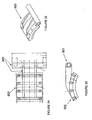
- FIGS. 26-28 and 29-31 Respectively for the bottom housing and top housing are Figures 26-28 and 29-31, the series of three figures being respectively top, end and Section AA views.
- Figures 32 to 34 are perspective, side and top views of the dropout opening door.
- thermokinetic mixers are especially described with reference to the art of thermokinetic mixers and the uses described for such mixers and as disclosed herein. It is well known in the art of thermokinetic mixers that tip speed of the shaft extensions is a critical a measure of the capability of the mixer to heat polymer particles by causing mixing chamber impinging collision induced the high speed rotation of the shaft. It is a repeated and a required teaching in the art that the shaft extensions comprise substantially smooth and rounded shaft extensions, albeit comprising substantially sinuous and rounded shafts and sometimes having at the shaft-distal end a rounded and small paddle with a face normal to the tangent of the circular rotation of the shaft extension.
- thermoset material normally without value for recycling or any use except for commingling at lower than 35 weight percent with thermoplastics, could be combined with as little as 25% thermoplastics for forming a useful article.
- the device suggested in the Good patent was the Draiswerke Gelimat® machine, as well known in this art.
- Such a device comprises no paddle shaped sections on its shaft extensions, consisting of a relatively amorphous smooth and substantially round shaft with some broad and rounded side to side bends. The smooth and rounded shape is formed such that the shaft extension does not cause polymer collision that would cause agglomeration by melting.
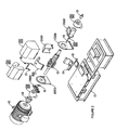
- Figures 1 and 2 show respectively assembled and exploded perspective views of the invention mixer assembly.
- the reference numbers of Figures 1 and 2 are used only for those figures, although the referenced component names refer to substantially identical components among all the figures.
- a frame 1 supports associated components such that a shaft assembly 2 is inserted in an axis of a shaft hole through end plate 3 and a feed screw hole through end plate 4, the two end plates defining enclosing ends of a mixing chamber cylinder, the bottom portion of the cylinder defined by the inside surface of the lower housing 5.
- Lower housing 5 comprises a dropout opening closed off during operation with discharge door 6.
- the upper housing 7 comprises an upper part of the cylinder of the inside surface of the mixing chamber of the invention.
- the feed housing 8 is adapted to permit feeding of material to the feed screw of the shaft assembly so that such material is, in combination with the feed screw rotation, compressingly forced into mixing chamber from an external feed.
- Door 6 rotatably closes about discharge door pivot pin 9.
- End plate 3 has attached to it a rack & pinion cylinder 18 with spacer 10 interposed.
- At the top of housing 7 is mounted a bracket 11 with which to support an IR temperature sensor 20 for the mixing chamber.
- Door guard 12 protects the sometimes high temperature door 5 from accidental human contact with dropout material.
- Rotary guard 13 and drive coupling guard 14 guard human operators from contact with rotating components during operation.
- Drive motor 15 is preferably an electric motor with sufficient power to accomplish the invention operation, but in a specific example below is about 111 Kw (150 HP).
- the pillow blocks 16 and 17 support the shaft assembly 2.
- Figure 3 shows an exploded view of the shaft assembly 2 of Figure 2.
- the reference numbers of Figure 3 are used only for that figure and in Figure 4, although the referenced component names refer to substantially identical components among all the figures.
- a series of connected shafts comprise shaft components 1 supported at one end on the bearing 6.
- the feed screw 2 engages at the visible end of its hollow shaft the noticeable spline of the shaft components 1 such that appropriate rotation of the shaft causes the feed screw also to rotate.
- One preferred form of the invention comprises the tooth bases 3 being connected to either of a left edge tooth 4 or a right edge tooth 5 by slots and keys and tooth base screws 8 to teeth 4 or 5, whereafter the bases 3 are connected by slots and keys and tooth base to shaft screws 7 to the shaft, thereby forming removable base 3 and teeth 4 or 5 assemblies.
- thermokinetic mixers This removable assembly concept for thermokinetic mixers is unknown in the prior art.
- the breadth of the concept of this aspect of the invention includes providing equivalent removable shaft extensions for all thermokinetic mixers.
- the disclosure herein enables the skilled person to adapt the removable extension concept to such prior art devices as disclosed above.
- the concept of the abutting slot and key attachments with securing screws has heretofore been unknown.
- the base 3 may be attached by welding wherein only a portion of the shaft extension is removably attached as described herein.
- the teeth 4 or 5 or equivalent end portion of a shaft extension are a single piece with a base 3 or its equivalent in the prior art, the entire shaft extension thereafter being removable as disclosed herein for base 3 from the shaft comprising slots therefore.
- First row slots teeth sets 101', second row slots teeth sets 102', third row slots teeth sets 103', and fourth row slots teeth sets 104' correspond respectively with the first row slots 101, second row slots 102, third row slots 103, and fourth row slots 104 as shown and described in and for Figure 4.
- the pattern of teeth 4 and 5 in Figure 3 are a preferred embodiment of the invention.
- a row slots teeth set comprises all teeth 4 or 5.
- all row slots teeth sets comprise all teeth 4 or 5 or each rotationally successive row slots teeth set comprises all teeth 4 followed by one of all teeth 5.
- each row slots teeth set comprises two teeth 4 or 5 whereby the rotationally adjacent row slots teeth sets to each such set comprises two teeth 5 or 4 respectively.
- FIG. 3 A most specific embodiment of Figure 3 shows first row slots teeth sets 101' with left to right teeth 5 / 4 / 4, second row slots teeth sets 102' with left to right teeth 5 / 4 / 5, third row slots teeth sets 103' with left to right teeth 4 / 5 / 4, and fourth row slots teeth sets 104' with left to right teeth 5 / 4 / 4.
- this pattern produces a set to set staggering of the teeth faces as they rotate into a plane passing through the shaft 100 axis.
- shaft components 1 are further shown to comprise an attachment shaft section 100 whereupon are located some of the attachment means for attaching bases 3 to the shaft components 1.
- first row slots 101, second row slots 102 and third row slots 103 are visible, a fourth row slots 104 existing on the opposite side of the section 100 and further disclosed in Figure 6.
- the slots and keys referenced herein comprise a preferred embodiment of abuttable slots having an open and closed end, the mateable key on another piece insertable into the open end and the first inserted end of the key then being moved from the open to the closed end of the slot to thereby abut the closed end of the slot. It is intended that rotation of the shaft 100 in the direction from the closed to open ends of the slots 101-104 will thereby cause the engaged first inserted end of the keys of the teeth bases to be pressed more securely into the slots 101-104 of shaft 100.
- each slot 101-104 has a slot length 105 in a preferred embodiment of about 4.4 cm (1.75 inches) divided exactly in two by one of two shaft axial planes normal to each other, whereby an open end of the slot is extended further along the shaft 100 such that the bases keys may be inserted, the further extension being about 1,6 cm (0.625 inches), the combined slot lengths equaling about 6,03 cm (2.375 inches).
- Each slot 101-104 further comprises a base to shaft screw 7 hole 106 threaded to receive screws 7.
- the holes 106 are oriented to encourage retention of the tooth base key in the slots 101-104.
- the slots 101-104 are about 3,2 cm (1.25 inches) wide and 1.9 cm (0.75 inches) deep with internal cross section notches extending into the slot rectangle about 6 mm (0.25 inches).
- the slot floor to floor width 107 is about 8,9 cm (3.5 inches).
- Hole 106 angle 108 is about 20 degrees.
- the slot centerline to centerline distance 110 is about 1.75, whereby it will be appreciated that each row slots teeth set is axially lengthwise staggered from its rotationally adjacent row slots teeth set.
- the staggering is such that teeth of two rotationally adjacent row slots teeth sets passing through an axial plane in operation rotation are equally spaced.
- Figure 10 shows teeth faces of the sets 101'-104' in solid lines as they would appear rotationally passing the plane view as shown by the teeth faces 103' TEETH FACES in Figure 9.
- broken lines in Figure 10 are shown the rotationally following set of teeth faces, as would be encountered by a particle in the mixing chamber striking a tooth face of one set if passing through the teeth of that set to encounter the teeth faces of the next set.
- all the sets 101'-104' comprise, as easily seen in Figure 10, left to right adjacent teeth faces 5 and 4 (as in Figure 3), such that the inclination of those adjacent tooth faces tends drives all particles encountered from just below the top inclined face in between the gap formed by such adjacent tooth faces.
- the major tooth faces of such adjacent teeth form a rough "V" shape with a gap in between. The effect of such combination of adjacent teeth causes the particles thus funneled to the gap to encounter the gap-filling tooth in the rotationally following set.
- the staggering of teeth in rotationally adjacent sets result in a substantially gap-filling action as shown in Figure 10 so that particles encountering a first set of teeth may strike them and/or be funneled to a gap between adjacent teeth in a set such that a rotationally following set tooth face is oriented to fill such a gap when it rotates to the position of the leading set.
- the tips of the teeth of sets 101'-104' when installed define a width 325 and a height 326 within an inside chamber circumference 327.
- Shaft components 1 further comprises spline attachment means 109 is constructed and oriented to securingly engage the appropriate end of a mating extension for shaft 100 and spline attachment means 109A constructed and oriented to securingly engage the appropriate end of a the feed screw 2 of Figure 3, thereby causing the feed screw to rotate with shaft components 1.
- Tooth base 200 has a base height 201 of about 8,9 cm (3.5 inches), a width 202 of about 6,03 cm (2.375 inches), a support width 203 of about 4,4 cm (1.75 inches).
- a top end of the base 200 comprises a slot 204 for receiving a key from a tooth and at the bottom a shaft key 205 for insertion into the shaft 100 slots 101-104.
- the key height 206 is just less than 6 mm (0.25 inches), the slot depth 207 is about 4,8 mm (0.19 inches), the key width 208 is just less than 3,2 cm (1.25 inches), the key attachment width 209 is just less than 1,9 cm (0.75 inches).
- the base 200 comprises a tooth base to shaft screw hole 210 for receiving a screw for securing the tooth 300 to base 200 after insertion of the tooth key into the slot 204.
- the base 200 comprises tooth to tooth base screw hole 211 for receiving a screw for securing the base 200 to shaft 100 after insertion of the base key 205 into a slot of slots 101-104.
- the slot base width 212 is about 2.22 cm (0.875 inches) and the slot top width 213 is about 1,3 mm (0.05 inches).
- Right leading edge tooth 300 (as shown in Figure 3 as teeth 5) comprises attachment means for attaching to the tooth base 200.
- the appropriately attached tooth 300 presents a tooth face to a shaft 100 axial plane when the tooth 300 rotates about shaft 100.
- the tooth face comprises a reticulated major face 300 having an acute angle with respect to said plane, the vertex of that acute angle being the leading edge 304 of the major face.
- the presentation of the leading edge 304 is preferably linear and parallel to the said plane, although such leading edge may be slightly angled into or away from said plane and still accomplish objects of the invention.
- the shape of the leading edge 304 may comprise smooth transitions or notches and still accomplish the object of the invention.
- thermokinetic mixers A forming of such an angled major face 304 on a tooth face is heretofore unknown in the art of thermokinetic mixers.
- the effect of the angled major face in operation of the mixer assembly is to drive a majority of mixing chamber particles encountering the angled major face to one side or another of the supported tooth.
- Prior art thermokinetic mixers are intended as devices for throwing particles at the inside surfaces of a mixing chamber.
- the present invention tends to retain particles within a rotational cylindrical space between the shaft 100 surface and the tips of the teeth until such particles melt and/or agglomerate or are captured by melted polymers at the extra-cylindrical space clearance between the tooth tips and the inside surface of the mixing chamber.
- the major angled faces of the teeth make the invention device specifically adapted to melt blending polymers and/or non-melting filler polymers or other material.
- the above disclosure as to the teeth face presentations in Figure 10 clearly show that mixing chamber particles will be driven not only against the teeth and inside surface of the mixing chamber, but also inevitably with great force against each other.
- the invention device permits an unexpectedly large number of non-recyclable or limited value recyclable materials to be made into very useful compositions after melt blending therein.
- the tooth 300 comprises in one preferred from a leading edge width 301 of about 8.1 cm (3.2 inches), a following edge width 302 about 6,4 cm (2.4 inches).
- a key 305 is formed in the upper convex portion of the L-shaped tooth 300, which key is insertable into the slot 204. The insertion can only be accomplished in one manner for the key 305 and slot 204 shown.
- the tooth 300 forms a protective cap or shield to the tooth base 200 as to encountering mixing chamber particles.
- a tooth to tooth base screw hole 306 receives the screw 8 as in Figure 3 for securing the tooth 300 to the tooth base 200.
- the tooth 200 further comprises a leading edge side 307, a following edge side 308, and a lower bevel face 309.
- Lower bevel face 309 comprises a portion of the tooth face below angled major face 304 in shaft 100 axis elevation. This face is preferred for avoiding agglomeration of melted particles at the shaft 100 to tooth base 200 transition, although such a face may be minimized or eliminated with substantially the function of the invention device preserved.
- Tooth height 310 is about 11,4 cm (4.5 inches), making total tooth sets 101/102 or 103/104 height 326 about 32,9 to 33 cm (12.95 to 12.98 inches) and total tooth sets 101/102 or 103/104 width 325 is about 21,0 cm (8.25 inches).
- Leading edge height 311 is about 8,44 cm (3.325 inches).
- Tooth 300 further comprises a lower face bottom edge 312 which rises to a lower face height 313 of about 1,9 cm (0.75 inches).
- Tooth length 314 is about 8,1 cm (3.2 inches) and tooth less leading edge length 315 is about 4.4 cm (1.75 inches).
- Top face 316 comprises a third portion of the tooth face. Faces 303 and 309 generally deflect particles in the mixing chamber toward the gap in teeth in a set.
- Top face 316 tends to drive particles into collision with the inside surface of the mixing chamber.
- Bottom slot width 319 is about 2,22 cm (0.875 inches)
- top slot width 320 is about 1,3 cm (0.50 inches)
- slot depth 321 is about 4,8 mm (0.19 inches)
- tooth width 322 is about 3,2 cm (1.25 inches).
- tooth top leading edge corner 324 becomes substantially worn after melt blending polymers and in fact the entire top transition edge between major face 303 and top face 316 becomes quite smooth and is abraded more than any other portion of the tooth in the preferred operation of melt blending.
- the mixing chamber inside surface outline 327 as in Figure 4 has a circular diameter of about 33 cm (13 inches) and a width of about 25 cm (10 inches), for a mixing chamber volume of about 21,7 litres (1325 cubic inches).
- the clearance between the tooth tips and the inside of the mixing chamber walls is about 1,3 mm (0.05 inches), thereby providing very little of the mixing chamber volume outside of the reach of the teeth.
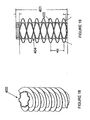
- Figures 18 and 20 show the feed screw 400 having shaft 404 with a length 401 of about 36 cm (14 inches)and two complementary screw blades 403, each having a pitch or crest to crest distance 402 of about 10 cm (4 inches).
- a single screw blade on the feed screw is adequate to achieve the invention objects.
- Feed screw end plate 500 comprises an end plate 501, an end plate base 502, end plate to housing bolt holes 503 in plate 501, a feed screw hole 504 sufficiently large to accommodate rotation of the feed screw 400, housing inside surface circumference 505 approximately defining the mixing chamber inside circumference of the circular section, and a mixing chamber surface 506.
- Shaft end plate 600 comprises an end plate 601, an end plate base 602, an end plate to housing bolt holes 603 in plate 601, feed screw hole 604 sufficiently large to permit rotation of shaft 100 without escape of particles or molten polymer, a housing inside surface circumference 605 approximately defining the mixing chamber inside circumference of the circular section and a mixing chamber surface 606.
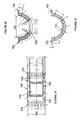
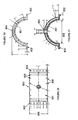
- FIG. 26 to 31 show views of the mixing chamber housings.
- Bottom housing 700 comprises an inside surface 701, flange section 702 for joining with top housing 800, an inside diameter 703, a width 704 of about 25 cm (10 inches), a dropout opening 705 about 46,8 cm 2 (7.25 inches square) for allowing molten material to drop from the mixing chamber after shaft 100 rotation has optionally stopped or an appropriate process temperature has been reached within the mixing chamber.
- End plate bolt holes 706 permit attachment to the end plates.
- Top housing 800 comprises an inside surface 801, flange section 802, inside diameter 803, sensor opening 804 for insertion of an IR sensor for mixing chamber temperature, a width 805 of about 25 cm (10 inches), and end plate bolt holes 806 to permit attachment to the end plates.
- Figures 31 to 33 disclose views of the dropout opening door 900 comprising a handle portion 901 and a door 902, which door is rotatable about a hinge for securingly closing the mixing chamber during operation.
- the invention device includes the concept of melt blending polymers and other meldable material into a composition capable of being made into a useful object.
- the shaft 100 is intended to rotate such that the teeth faces will collide with particles of substantial size (about the feed screw blades separation width) to powders.
- the housing 8 of Figures 1 and 2 accommodate insertion of such particles.
- the feed screw forces the particles into the mixing chamber to comminuted and melt blended.
- the rotational speed of the shaft can vary from below about 1800 rpm (to about 1500 rpm) to above about 3600 rpm. The choice of shaft speed will depend on the polymers and other materials being processed and the processing temperature desired to be reached.
- a mixture with a very high weight percentage of PVC may be melt blended at 1800 rpm to its processing temperature, say around 120-200 C as measured by the IR sensor for the mixing chamber.
- the dropout door preferably instantly closes after the release of the melt blended charge, thereby initiating feed of another amount of charge material to housing 8, feed screw transfer to the mixing chamber, heating by thermokinetic effect and release from the mixing chamber through the dropout door once again without substantial adhesion to the shaft or teeth or shaft extensions.
- the mixing chamber sensed temperature falls upon introduction of a new feed charge to the mixing chamber.
- the average cycle time for melt blending a charge for the device of the specific example is about 5-8 seconds. Some materials in the charge to the mixing chamber with low melting temperatures, such as PVC, have a lower cycle time (by a few seconds) while other materials take longer.
- the invention device heats and melts a mixing chamber mixture of polyolefins to about 230 C in about 5 seconds.
- a more preferred operating speed is about 2800 rpm so that a desired ultimate batch temperature may be more easily controlled and obtained.
- thermokinetic heating and melt blending of a very broad range of incompatible materials may be so processed.
- the top and bottom housings are double walled so that water can be flowed through them to cool the housing during operation. It is preferred that the clearance between the tips of the teeth and the mixing chamber wall be small, although some of the objects of the invention device could be achieved with substantial clearance therefore.
- the number of teeth in each rotationally successive set should be equal and staggered as described above although using from 2 to 10 teeth in each seat will accomplish the ends of the invention device. It will be clear from this disclosure that increasing the number of teeth or extending their tip to tip height requires an expansion of the mixing chamber and therefore an increase in the drive motor for the shaft 100 and feed screw. Those adaptations will permit an increase in the batch size processed.
- the volume of the material to be processed in the invention device should be limited to about less than the volume of the mixing chamber less the volume of the shaft 100 and sets 101'-104'. An invention device using only two sets 101' and 103' or 102' and 104' may be used to accomplish some of the objects of the invention, although use of all four sets are preferred.
- the acute angle of the major face with respect to a plane including the shaft axis is as shown in Figure 15 is about 45 degrees, although the invention may be practiced with such angles equaling from 5 to 85 degrees, more preferably 20 to 70 degrees, and most preferably from 30 to 60 degrees.
- thermokinetic mixer also comprises a replaceable wear surface case or body hardened on an inner surface to a high Rockwell number where the wear surface substantially comprises the entire inside surface of the mixing chamber.
- this would mean an inside surface of inner jackets would substantially comprise surfaces 701 and 801 such that the underlying structural support would maintain the position of the jackets in the positions of the surfaces 701 and 801 as shown in the Figures.
- the replaceability of the jackets reduces the cost of repairing inevitable wear on the jackets from melt blend processing, especially where substantial processing of unsorted trash is performed comprising metal and silica glass pieces.
- the invention assembly also comprises means for removeably mounting the feed screw to the rotation shaft for replacement for wear.
- the mixing assembly of the present invention has dramatically expanded the potential for melt blended compositions made therefrom.
- the Good patent discloses the well known prior art device, an ultra-high speed thermokinetic mixing device, such as the one produced by Draiswerke, Inc. and described in their brochure entitled "High Speed Thermokinetic Mixing, Compounding, Fluxing" (thermokinetic mixer, as described herein).
- the Draiswerke, Inc. device called the Gelimat® heats thermokinetically through particle impingement against the interior surface of the mixing chamber.
- melt blending of a very finely divided (35-100 mesh) thermoset material and a shredded or chopped thermoplastic polyolefin resin may be accomplished by external heating in heated extrusion means to produce an extrudable material, such melt blending is limited by inadequate mixing within the barrel of the heated extruder.
- the Good patent further discloses that using a device like the Gelimat® or a similar thermokinetic mixer as a device for practicing melt blending, wherein as about 6 mm to 1,3 cm (0.25-0.5 inch) flakes are added to the Gelimat® with shredded or chopped thermoplastic polyolefin resin. Extremely rapid heating and sheer grinding of relatively large particles 6 mm to 1,3 cm ((0.25-0.5 inches) in diameter) of thermoset material occurs and enhances melt blending and homogeneity. The melt blend is created in seconds in the devices like the Gelimat® as opposed to requiring substantially longer in a conventional extruder.
- the prior art thermokinetic mixers have proven limits, as disclosed in the Good patent, in melt blending compositions.
- thermokinetic melt blending comprise an very important departure from the thermokinetic mixer art.
- polymer or polymer containing particles within the mixing chamber obtain their thermokinetic heating primarily by their impact and deflection with the shaft extensions while a relatively lesser degree of heating is obtained by the particle impact with the inside surface of the mixing chamber.
- the introduction of means for maintaining substantially all the mixing chamber particles in the rotational field of the shaft extensions where the shaft extensions have a substantial defined and articulated leading edge means that those mixing chamber particles are subjected not only to repetitive thermokinetic heating deflection from the shaft extensions but also repetitive and significant chopping action from the sharply defined leading edge of the teeth.
- Prior art shaft extensions are smoothed and arcuately angular as to the rotating face surfaces encountering mixing chamber particles.
- the invention device permits thermokinetic melt blending of materials, shapes and textures heretofore impossible to so process.
Landscapes
- Chemical & Material Sciences (AREA)
- Chemical Kinetics & Catalysis (AREA)
- Engineering & Computer Science (AREA)
- Mechanical Engineering (AREA)
- Polymers & Plastics (AREA)
- Health & Medical Sciences (AREA)
- Medicinal Chemistry (AREA)
- Life Sciences & Earth Sciences (AREA)
- Organic Chemistry (AREA)
- Wood Science & Technology (AREA)
- Processing And Handling Of Plastics And Other Materials For Molding In General (AREA)
- Compositions Of Macromolecular Compounds (AREA)
- Pharmaceuticals Containing Other Organic And Inorganic Compounds (AREA)
- Medicines Containing Material From Animals Or Micro-Organisms (AREA)
- Processes Of Treating Macromolecular Substances (AREA)
- Compounds Of Unknown Constitution (AREA)
- Accessories For Mixers (AREA)
- Control Of High-Frequency Heating Circuits (AREA)
- Agricultural Chemicals And Associated Chemicals (AREA)
Abstract
Description
- This invention relates to solids for use as bricks, building blocks, landscaping blocks, walkway stones, railroad ties, building blocks, steps, retaining wall blocks and other structural components. In particular, this invention provides for the use of a substantial proportion of a thermokinetically molten polymeric binder and optionally other components in a feed mixture material to be compressed in a molten state and solidified to form solids, including building blocks, landscaping blocks and the like.
- The relatively high cost of re-ground or recycled polymers has barred their use in the substantial quantities required for large, low cost members such as bricks, building blocks, landscaping blocks, walkway stones, railroad ties, building blocks, steps, retaining wall blocks and other structural components. Where cement or mineral based mixtures are used as binders for competing products, the non-competitive cost of using polymer binders in structural members has been, in the prior art, an effective hurdle heretofore not traversed. The invention process uses a novel method and composition to overcome this hurdle.
- US Patent 5,895,790 discloses thermokinetic mixers used for melt blending, a novel application for that device. The invention therein economically recovered polymer blends and waste thermoset material into useful products by first forming a predictable quality thermoset material from disparate polymers and then melt blending the thermoset material with a thermoplastic material into the useful products.
- US Patent 4808665 discloses shaped articles are made from blends of rubber and plastic in which the rubber is in the form of discrete vulcanized particles dispersed in the plastic. After shaping the articles, they are exposed to free-radical crosslinking which converts the blends from thermoplastics to thermosets. The blends were formed in a low rotation speed device operating at around 100 rpm.
- US Patent 4,789,597 discloses an very important teaching in the prior art with regard to thermokinetic mixers, or "high flux" mixers as disclosed in that patent. It is critical to the effective operation of the device to prevent melting of the chamber processed particles. In this patent, chemically reactive agents are locked to particles of suitable synthetic resins without "wholly fluxing" or melting the resins. Thus a high quality intermediate product is obtained having no premature reaction taking place, suitable for further techniques. The process comprises the steps of intensively mixing and thermokinetically heating a batch of finely divided resin particles, with a chemically reactive agent, in an enclosed mixing chamber with a plurality of blades attached to arms rotating about a central axis within the chamber, and having a blade tip speed of at least about 18 meters per second, mixing the batch until the chemically reactive agent is locked to the resin particles, ensuring that temperature of the batch stays well below decomposition temperature of the reactive agent and below fluxing temperature of the resin particles, discharging the batch from the mixing chamber and cooling the discharged batch to avoid agglomeration of the resin particles. It is clear from the Table I disclosure in that patent that operating with tip speeds in excess of an allowable level for a specific polymer will result in unwanted "occasional agglomerates" which must be separated from and disposed
- EP 0 976 442 discloses a mixer having sixteen paddles arranged as four rows around a shaft. The sixteen paddles are identical. The shaft rotates inside a cylindrical mixing chamber.
- According to the present invention, there is provided a thermokinetic mixer as set out at
claim 1. - The present invention comprises a novel thermokinetic mixer. In one form of the invention, the mixing chamber shaft projections are removable at least in part and replaceable without cutting the projections from the shaft. In another form of the invention, only a tip portion of such projections are removable and replaceable without such cutting.
- In yet another form of the invention, shaft projections into the mixing chamber comprise a tooth having a substantially reticulated face forming a deflecting surface such that substantially all mixing chamber particles encountering the tooth strike and are deflected at an incident substantially lateral angle from the deflecting surface.
- The invention may be used for a novel method of melt blending many grades and processing products of single polymers for primary formation into a useful product or recycling into useful products as well as forming products from a wide variety of post-user or post-consumer polymers, especially those previously unknown to be reformable into useful products such as for PVC and styrene in high relative weight percent relative to all polymers in such a product.
- The invention may comprise a two piece tooth effectively attached to the rotating shaft. At least one of the pieces comprises the entire deflecting surface which is easily replaceable after substantial wear from high speed and/or high temperature use in melt blending or physical compounding polymers within the mixing chamber. It has been unknown that the high temperature and/or high speed use of a thermokinetic mixer to melt blend polymers as in the Good patent (US Patent 5895790) would cause dramatically accelerated wear on the prior art thermokinetic mixer shaft extensions. The prior art use outside of the Good patent repeatedly confine operation of such mixers to strict limits on upper temperatures and rotation speeds. Outside of the Good patent, the prior art used thermokinetic mixers only for compounding short of melt blending or chemical reaction between particles, i.e., the product does not emerge from the mixing chamber in a molten state. The present inventors found to their surprise that exceeding the recommended mixture temperatures and rotation speeds as disclosed in the Good patent resulted in short effective life for the shaft extensions which drive the mix chamber particles into the side walls of the mix chamber to achieve the melt blending effect.
- In yet another aspect of the present invention, the disclosed patterns of deflecting surfaces as developed in the side by side arrangement of shaft-axis rows of teeth have especially advantageous effects in achieving melt blending of a wider range of polymers than contemplated in the Good patent.
-
- Figures 1 and 2 are perspective views of the invention mixer assembly, respectively assembled and exploded views.
- Figure 3 is an exploded view of the shaft assembly of Figure 2.
- Figure 4 is a side view of the shaft components and a sample set of teeth faces.
- Figures 5-9 are respectively cross sections AA and BB and sections C, D, and E of Figure 4.
- Figure 10 are teeth face orientations of sets according to the invention of Figure 2.
- Figures 11-13 are perspective, side and end views of a tooth base according to the invention.
- Figures 14-17 are perspective, top, side and end views of a tooth according to the invention.
- Figures 18 and 19 are perspective and broken line side views of the feed screw.
- Respectively for the feed screw end plate and the shaft end plate are Figures 20-21 and 22-24, the series of three figures being respectively side, edge and top views.
- Respectively for the bottom housing and top housing are Figures 26-28 and 29-31, the series of three figures being respectively top, end and Section AA views.
- Figures 32 to 34 are perspective, side and top views of the dropout opening door.
- The invention is now discussed with reference to the Figures. The invention is especially described with reference to the art of thermokinetic mixers and the uses described for such mixers and as disclosed herein. It is well known in the art of thermokinetic mixers that tip speed of the shaft extensions is a critical a measure of the capability of the mixer to heat polymer particles by causing mixing chamber impinging collision induced the high speed rotation of the shaft. It is a repeated and a required teaching in the art that the shaft extensions comprise substantially smooth and rounded shaft extensions, albeit comprising substantially sinuous and rounded shafts and sometimes having at the shaft-distal end a rounded and small paddle with a face normal to the tangent of the circular rotation of the shaft extension. This construction is consistent with the uses to which such prior art devices have been primarily used, i.e., except for the Good patent, for non-melting mixing and compounding of polymers. The Good patent disclosed that thermoset material, normally without value for recycling or any use except for commingling at lower than 35 weight percent with thermoplastics, could be combined with as little as 25% thermoplastics for forming a useful article. The device suggested in the Good patent was the Draiswerke Gelimat® machine, as well known in this art. Such a device comprises no paddle shaped sections on its shaft extensions, consisting of a relatively amorphous smooth and substantially round shaft with some broad and rounded side to side bends. The smooth and rounded shape is formed such that the shaft extension does not cause polymer collision that would cause agglomeration by melting.
- Figures 1 and 2 show respectively assembled and exploded perspective views of the invention mixer assembly. The reference numbers of Figures 1 and 2 are used only for those figures, although the referenced component names refer to substantially identical components among all the figures. For Figures 1 and 2, a
frame 1 supports associated components such that ashaft assembly 2 is inserted in an axis of a shaft hole through end plate 3 and a feed screw hole through end plate 4, the two end plates defining enclosing ends of a mixing chamber cylinder, the bottom portion of the cylinder defined by the inside surface of thelower housing 5.Lower housing 5 comprises a dropout opening closed off during operation with discharge door 6. The upper housing 7 comprises an upper part of the cylinder of the inside surface of the mixing chamber of the invention. Thefeed housing 8 is adapted to permit feeding of material to the feed screw of the shaft assembly so that such material is, in combination with the feed screw rotation, compressingly forced into mixing chamber from an external feed. Door 6 rotatably closes about discharge door pivot pin 9. End plate 3 has attached to it a rack & pinion cylinder 18 with spacer 10 interposed. At the top of housing 7 is mounted a bracket 11 with which to support an IR temperature sensor 20 for the mixing chamber.Door guard 12 protects the sometimeshigh temperature door 5 from accidental human contact with dropout material.Rotary guard 13 and drive coupling guard 14 guard human operators from contact with rotating components during operation. Drivemotor 15 is preferably an electric motor with sufficient power to accomplish the invention operation, but in a specific example below is about 111 Kw (150 HP). The pillow blocks 16 and 17 support theshaft assembly 2. - Figure 3 shows an exploded view of the
shaft assembly 2 of Figure 2. The reference numbers of Figure 3 are used only for that figure and in Figure 4, although the referenced component names refer to substantially identical components among all the figures. A series of connected shafts compriseshaft components 1 supported at one end on the bearing 6. Thefeed screw 2 engages at the visible end of its hollow shaft the noticeable spline of theshaft components 1 such that appropriate rotation of the shaft causes the feed screw also to rotate. One preferred form of the invention comprises the tooth bases 3 being connected to either of a left edge tooth 4 or aright edge tooth 5 by slots and keys and tooth base screws 8 toteeth 4 or 5, whereafter the bases 3 are connected by slots and keys and tooth base to shaft screws 7 to the shaft, thereby forming removable base 3 andteeth 4 or 5 assemblies. This removable assembly concept for thermokinetic mixers is unknown in the prior art. The breadth of the concept of this aspect of the invention includes providing equivalent removable shaft extensions for all thermokinetic mixers. The disclosure herein enables the skilled person to adapt the removable extension concept to such prior art devices as disclosed above. The concept of the abutting slot and key attachments with securing screws has heretofore been unknown. More specifically, the base 3 may be attached by welding wherein only a portion of the shaft extension is removably attached as described herein. Or in the alternate, theteeth 4 or 5 or equivalent end portion of a shaft extension are a single piece with a base 3 or its equivalent in the prior art, the entire shaft extension thereafter being removable as disclosed herein for base 3 from the shaft comprising slots therefore. First row slots teeth sets 101', second row slots teeth sets 102', third row slots teeth sets 103', and fourth row slots teeth sets 104' correspond respectively with thefirst row slots 101,second row slots 102,third row slots 103, andfourth row slots 104 as shown and described in and for Figure 4. The pattern ofteeth 4 and 5 in Figure 3 are a preferred embodiment of the invention. In one embodiment, a row slots teeth set comprises allteeth 4 or 5. In another embodiment, all row slots teeth sets comprise allteeth 4 or 5 or each rotationally successive row slots teeth set comprises all teeth 4 followed by one of allteeth 5. In the embodiment of Figure 3, each row slots teeth set comprises twoteeth 4 or 5 whereby the rotationally adjacent row slots teeth sets to each such set comprises twoteeth 5 or 4 respectively. A most specific embodiment of Figure 3 shows first row slots teeth sets 101' with left toright teeth 5 / 4 / 4, second row slots teeth sets 102' with left toright teeth 5 / 4 / 5, third row slots teeth sets 103' with left to right teeth 4 / 5 / 4, and fourth row slots teeth sets 104' with left toright teeth 5 / 4 / 4. As shown in Figure 4, this pattern produces a set to set staggering of the teeth faces as they rotate into a plane passing through theshaft 100 axis. - With reference to rest of the Figures,
shaft components 1 are further shown to comprise anattachment shaft section 100 whereupon are located some of the attachment means for attaching bases 3 to theshaft components 1. In this side view,first row slots 101,second row slots 102 andthird row slots 103 are visible, afourth row slots 104 existing on the opposite side of thesection 100 and further disclosed in Figure 6. - The slots and keys referenced herein comprise a preferred embodiment of abuttable slots having an open and closed end, the mateable key on another piece insertable into the open end and the first inserted end of the key then being moved from the open to the closed end of the slot to thereby abut the closed end of the slot. It is intended that rotation of the
shaft 100 in the direction from the closed to open ends of the slots 101-104 will thereby cause the engaged first inserted end of the keys of the teeth bases to be pressed more securely into the slots 101-104 ofshaft 100. Thus, each slot 101-104 has aslot length 105 in a preferred embodiment of about 4.4 cm (1.75 inches) divided exactly in two by one of two shaft axial planes normal to each other, whereby an open end of the slot is extended further along theshaft 100 such that the bases keys may be inserted, the further extension being about 1,6 cm (0.625 inches), the combined slot lengths equaling about 6,03 cm (2.375 inches). - Each slot 101-104 further comprises a base to shaft screw 7 hole 106 threaded to receive screws 7. The holes 106 are oriented to encourage retention of the tooth base key in the slots 101-104. The slots 101-104 are about 3,2 cm (1.25 inches) wide and 1.9 cm (0.75 inches) deep with internal cross section notches extending into the slot rectangle about 6 mm (0.25 inches). The slot floor to
floor width 107 is about 8,9 cm (3.5 inches). Hole 106angle 108 is about 20 degrees. For slots 101-104, the slot centerline tocenterline distance 110 is about 1.75, whereby it will be appreciated that each row slots teeth set is axially lengthwise staggered from its rotationally adjacent row slots teeth set. Preferably, the staggering is such that teeth of two rotationally adjacent row slots teeth sets passing through an axial plane in operation rotation are equally spaced. As a definition of a specific example herein, Figure 10 shows teeth faces of the sets 101'-104' in solid lines as they would appear rotationally passing the plane view as shown by the teeth faces 103' TEETH FACES in Figure 9. In broken lines in Figure 10 are shown the rotationally following set of teeth faces, as would be encountered by a particle in the mixing chamber striking a tooth face of one set if passing through the teeth of that set to encounter the teeth faces of the next set. For example, all the sets 101'-104' comprise, as easily seen in Figure 10, left to right adjacent teeth faces 5 and 4 (as in Figure 3), such that the inclination of those adjacent tooth faces tends drives all particles encountered from just below the top inclined face in between the gap formed by such adjacent tooth faces. The major tooth faces of such adjacent teeth form a rough "V" shape with a gap in between. The effect of such combination of adjacent teeth causes the particles thus funneled to the gap to encounter the gap-filling tooth in the rotationally following set. Notwithstanding this more limited, albeit preferred embodiment, of adjacency of teeth faces, it is preferred that the staggering of teeth in rotationally adjacent sets result in a substantially gap-filling action as shown in Figure 10 so that particles encountering a first set of teeth may strike them and/or be funneled to a gap between adjacent teeth in a set such that a rotationally following set tooth face is oriented to fill such a gap when it rotates to the position of the leading set. As further described below, the tips of the teeth of sets 101'-104' when installed define awidth 325 and aheight 326 within aninside chamber circumference 327. -
Shaft components 1 further comprises spline attachment means 109 is constructed and oriented to securingly engage the appropriate end of a mating extension forshaft 100 and spline attachment means 109A constructed and oriented to securingly engage the appropriate end of a thefeed screw 2 of Figure 3, thereby causing the feed screw to rotate withshaft components 1. - Figures 11-17 are discussed now for a detailed discussion of the teeth bases and teeth. The specific example described is an optimized device. This disclosure more broadly includes replaceable shaft extensions or at least upper portions of shaft extensions for thermokinetic mixers.
Tooth base 200 has abase height 201 of about 8,9 cm (3.5 inches), awidth 202 of about 6,03 cm (2.375 inches), asupport width 203 of about 4,4 cm (1.75 inches). A top end of thebase 200 comprises aslot 204 for receiving a key from a tooth and at the bottom ashaft key 205 for insertion into theshaft 100 slots 101-104. Thekey height 206 is just less than 6 mm (0.25 inches), theslot depth 207 is about 4,8 mm (0.19 inches), thekey width 208 is just less than 3,2 cm (1.25 inches), thekey attachment width 209 is just less than 1,9 cm (0.75 inches). Thebase 200 comprises a tooth base toshaft screw hole 210 for receiving a screw for securing thetooth 300 tobase 200 after insertion of the tooth key into theslot 204. Thebase 200 comprises tooth to toothbase screw hole 211 for receiving a screw for securing the base 200 toshaft 100 after insertion of the base key 205 into a slot of slots 101-104. Theslot base width 212 is about 2.22 cm (0.875 inches) and theslot top width 213 is about 1,3 mm (0.05 inches). - Right leading edge tooth 300 (as shown in Figure 3 as teeth 5) comprises attachment means for attaching to the
tooth base 200. When the tooth base is engaged with a slot of slots 101-104, the appropriately attachedtooth 300 presents a tooth face to ashaft 100 axial plane when thetooth 300 rotates aboutshaft 100. The tooth face comprises a reticulatedmajor face 300 having an acute angle with respect to said plane, the vertex of that acute angle being theleading edge 304 of the major face. The presentation of theleading edge 304 is preferably linear and parallel to the said plane, although such leading edge may be slightly angled into or away from said plane and still accomplish objects of the invention. The shape of theleading edge 304 may comprise smooth transitions or notches and still accomplish the object of the invention. - A forming of such an angled
major face 304 on a tooth face is heretofore unknown in the art of thermokinetic mixers. The effect of the angled major face in operation of the mixer assembly is to drive a majority of mixing chamber particles encountering the angled major face to one side or another of the supported tooth. Prior art thermokinetic mixers are intended as devices for throwing particles at the inside surfaces of a mixing chamber. The present invention tends to retain particles within a rotational cylindrical space between theshaft 100 surface and the tips of the teeth until such particles melt and/or agglomerate or are captured by melted polymers at the extra-cylindrical space clearance between the tooth tips and the inside surface of the mixing chamber. The major angled faces of the teeth make the invention device specifically adapted to melt blending polymers and/or non-melting filler polymers or other material. The above disclosure as to the teeth face presentations in Figure 10 clearly show that mixing chamber particles will be driven not only against the teeth and inside surface of the mixing chamber, but also inevitably with great force against each other. The invention device permits an unexpectedly large number of non-recyclable or limited value recyclable materials to be made into very useful compositions after melt blending therein. - The
tooth 300 comprises in one preferred from aleading edge width 301 of about 8.1 cm (3.2 inches), a followingedge width 302 about 6,4 cm (2.4 inches). A key 305 is formed in the upper convex portion of the L-shapedtooth 300, which key is insertable into theslot 204. The insertion can only be accomplished in one manner for the key 305 and slot 204 shown. Thus, thetooth 300 forms a protective cap or shield to thetooth base 200 as to encountering mixing chamber particles. A tooth to toothbase screw hole 306 receives thescrew 8 as in Figure 3 for securing thetooth 300 to thetooth base 200. Thetooth 200 further comprises aleading edge side 307, a followingedge side 308, and alower bevel face 309.Lower bevel face 309 comprises a portion of the tooth face below angledmajor face 304 inshaft 100 axis elevation. This face is preferred for avoiding agglomeration of melted particles at theshaft 100 totooth base 200 transition, although such a face may be minimized or eliminated with substantially the function of the invention device preserved. -
Tooth height 310 is about 11,4 cm (4.5 inches), making total tooth sets 101/102 or 103/104height 326 about 32,9 to 33 cm (12.95 to 12.98 inches) and total tooth sets 101/102 or 103/104width 325 is about 21,0 cm (8.25 inches). Leadingedge height 311 is about 8,44 cm (3.325 inches).Tooth 300 further comprises a lowerface bottom edge 312 which rises to alower face height 313 of about 1,9 cm (0.75 inches).Tooth length 314 is about 8,1 cm (3.2 inches) and tooth lessleading edge length 315 is about 4.4 cm (1.75 inches).Top face 316 comprises a third portion of the tooth face.Faces Top face 316 tends to drive particles into collision with the inside surface of the mixing chamber.Bottom slot width 319 is about 2,22 cm (0.875 inches),top slot width 320 is about 1,3 cm (0.50 inches),slot depth 321 is about 4,8 mm (0.19 inches), andtooth width 322 is about 3,2 cm (1.25 inches). - Following
edge 323 is the edge ofmajor face 303 oppositeleading edge 304. It has been observed that in operation tooth top leadingedge corner 324 becomes substantially worn after melt blending polymers and in fact the entire top transition edge betweenmajor face 303 andtop face 316 becomes quite smooth and is abraded more than any other portion of the tooth in the preferred operation of melt blending. - The mixing chamber inside
surface outline 327 as in Figure 4 has a circular diameter of about 33 cm (13 inches) and a width of about 25 cm (10 inches), for a mixing chamber volume of about 21,7 litres (1325 cubic inches). The clearance between the tooth tips and the inside of the mixing chamber walls is about 1,3 mm (0.05 inches), thereby providing very little of the mixing chamber volume outside of the reach of the teeth. - Figures 18 and 20 show the
feed screw 400 havingshaft 404 with alength 401 of about 36 cm (14 inches)and two complementary screw blades 403, each having a pitch or crest to crestdistance 402 of about 10 cm (4 inches). A single screw blade on the feed screw is adequate to achieve the invention objects. - Figures 20 to 25 show views of the mixing chamber end plates. Feed
screw end plate 500 comprises anend plate 501, anend plate base 502, end plate to housing bolt holes 503 inplate 501, afeed screw hole 504 sufficiently large to accommodate rotation of thefeed screw 400, housing insidesurface circumference 505 approximately defining the mixing chamber inside circumference of the circular section, and a mixing chamber surface 506.Shaft end plate 600 comprises anend plate 601, anend plate base 602, an end plate to housing bolt holes 603 inplate 601, feedscrew hole 604 sufficiently large to permit rotation ofshaft 100 without escape of particles or molten polymer, a housing insidesurface circumference 605 approximately defining the mixing chamber inside circumference of the circular section and a mixing chamber surface 606. - Figures 26 to 31 show views of the mixing chamber housings.
Bottom housing 700 comprises aninside surface 701,flange section 702 for joining withtop housing 800, aninside diameter 703, awidth 704 of about 25 cm (10 inches), adropout opening 705 about 46,8 cm2 (7.25 inches square) for allowing molten material to drop from the mixing chamber aftershaft 100 rotation has optionally stopped or an appropriate process temperature has been reached within the mixing chamber. End plate bolt holes 706 permit attachment to the end plates. -
Top housing 800 comprises aninside surface 801,flange section 802, insidediameter 803,sensor opening 804 for insertion of an IR sensor for mixing chamber temperature, awidth 805 of about 25 cm (10 inches), and end plate bolt holes 806 to permit attachment to the end plates. - Figures 31 to 33 disclose views of the
dropout opening door 900 comprising ahandle portion 901 and adoor 902, which door is rotatable about a hinge for securingly closing the mixing chamber during operation. - The invention device includes the concept of melt blending polymers and other meldable material into a composition capable of being made into a useful object. The
shaft 100 is intended to rotate such that the teeth faces will collide with particles of substantial size (about the feed screw blades separation width) to powders. When in operation, thehousing 8 of Figures 1 and 2 accommodate insertion of such particles. The feed screw forces the particles into the mixing chamber to comminuted and melt blended. The rotational speed of the shaft can vary from below about 1800 rpm (to about 1500 rpm) to above about 3600 rpm. The choice of shaft speed will depend on the polymers and other materials being processed and the processing temperature desired to be reached. For example, a mixture with a very high weight percentage of PVC (normally not recyclable or only in very low relative amounts with other polymers) may be melt blended at 1800 rpm to its processing temperature, say around 120-200 C as measured by the IR sensor for the mixing chamber. - When a desired processing temperature is sensed by the temperature sensor for the charged amount of one or several materials within the mixing chamber and contrary to the methods of the prior art for melt blending for thermokinetic mixers, rotation of the shaft is preferably continued at the set rotation speed. It has been an unexpected result that an opening of the dropout door will substantially empty the mixing chamber of a substantially uniform composition of molten and moldable material without having to stop the shaft rotation. It is preferred that a control means cause the opening of the dropout door to occur at the sensing of an upper limit temperature by the temperature sensor. The dropout door preferably instantly closes after the release of the melt blended charge, thereby initiating feed of another amount of charge material to
housing 8, feed screw transfer to the mixing chamber, heating by thermokinetic effect and release from the mixing chamber through the dropout door once again without substantial adhesion to the shaft or teeth or shaft extensions.. The mixing chamber sensed temperature falls upon introduction of a new feed charge to the mixing chamber. The average cycle time for melt blending a charge for the device of the specific example is about 5-8 seconds. Some materials in the charge to the mixing chamber with low melting temperatures, such as PVC, have a lower cycle time (by a few seconds) while other materials take longer. At around 3600 rpm, the invention device heats and melts a mixing chamber mixture of polyolefins to about 230 C in about 5 seconds. A more preferred operating speed is about 2800 rpm so that a desired ultimate batch temperature may be more easily controlled and obtained. - It is a less preferable method of operation to stop the shaft rotation for emptying of the mixing chamber, although the objects of the thermokinetic heating and melt blending of a very broad range of incompatible materials may be so processed.
- The top and bottom housings are double walled so that water can be flowed through them to cool the housing during operation. It is preferred that the clearance between the tips of the teeth and the mixing chamber wall be small, although some of the objects of the invention device could be achieved with substantial clearance therefore.
- The number of teeth in each rotationally successive set should be equal and staggered as described above although using from 2 to 10 teeth in each seat will accomplish the ends of the invention device. It will be clear from this disclosure that increasing the number of teeth or extending their tip to tip height requires an expansion of the mixing chamber and therefore an increase in the drive motor for the
shaft 100 and feed screw. Those adaptations will permit an increase in the batch size processed. The volume of the material to be processed in the invention device should be limited to about less than the volume of the mixing chamber less the volume of theshaft 100 and sets 101'-104'. An invention device using only twosets 101' and 103' or 102' and 104' may be used to accomplish some of the objects of the invention, although use of all four sets are preferred. - The acute angle of the major face with respect to a plane including the shaft axis is as shown in Figure 15 is about 45 degrees, although the invention may be practiced with such angles equaling from 5 to 85 degrees, more preferably 20 to 70 degrees, and most preferably from 30 to 60 degrees.
- The invention thermokinetic mixer also comprises a replaceable wear surface case or body hardened on an inner surface to a high Rockwell number where the wear surface substantially comprises the entire inside surface of the mixing chamber. In the specific example, this would mean an inside surface of inner jackets would substantially comprise
surfaces surfaces - The invention assembly also comprises means for removeably mounting the feed screw to the rotation shaft for replacement for wear.
- The mixing assembly of the present invention has dramatically expanded the potential for melt blended compositions made therefrom.
- The Good patent discloses the well known prior art device, an ultra-high speed thermokinetic mixing device, such as the one produced by Draiswerke, Inc. and described in their brochure entitled "High Speed Thermokinetic Mixing, Compounding, Fluxing" (thermokinetic mixer, as described herein). The Draiswerke, Inc. device called the Gelimat® heats thermokinetically through particle impingement against the interior surface of the mixing chamber. Although melt blending of a very finely divided (35-100 mesh) thermoset material and a shredded or chopped thermoplastic polyolefin resin may be accomplished by external heating in heated extrusion means to produce an extrudable material, such melt blending is limited by inadequate mixing within the barrel of the heated extruder.
- The Good patent further discloses that using a device like the Gelimat® or a similar thermokinetic mixer as a device for practicing melt blending, wherein as about 6 mm to 1,3 cm (0.25-0.5 inch) flakes are added to the Gelimat® with shredded or chopped thermoplastic polyolefin resin. Extremely rapid heating and sheer grinding of relatively large particles 6 mm to 1,3 cm ((0.25-0.5 inches) in diameter) of thermoset material occurs and enhances melt blending and homogeneity. The melt blend is created in seconds in the devices like the Gelimat® as opposed to requiring substantially longer in a conventional extruder. The prior art thermokinetic mixers have proven limits, as disclosed in the Good patent, in melt blending compositions. For instance, only a relatively low percentage of PVC or polystyrene were capable of being melt blended into a moldable material. It is clear from the shaft extension configurations of the Gelimat® and other prior art thermokinetic mixers that their designs originated in the art of non-melt blending compounding. Those shaft extensions in a front view comprise substantial "paddle" portions at their free ends provided to drive the mixing chamber particles into the inside surface of the mixing chamber.
- In contrast, the invention means for thermokinetic melt blending comprise an very important departure from the thermokinetic mixer art. As appreciated by the above description of the invention means, polymer or polymer containing particles within the mixing chamber obtain their thermokinetic heating primarily by their impact and deflection with the shaft extensions while a relatively lesser degree of heating is obtained by the particle impact with the inside surface of the mixing chamber. The introduction of means for maintaining substantially all the mixing chamber particles in the rotational field of the shaft extensions where the shaft extensions have a substantial defined and articulated leading edge means that those mixing chamber particles are subjected not only to repetitive thermokinetic heating deflection from the shaft extensions but also repetitive and significant chopping action from the sharply defined leading edge of the teeth. Prior art shaft extensions are smoothed and arcuately angular as to the rotating face surfaces encountering mixing chamber particles. The invention device permits thermokinetic melt blending of materials, shapes and textures heretofore impossible to so process.
Claims (11)
- A thermokinetic mixer comprising:a substantially cylindrical mixing chamber (Fig. 2: 3, 4, 5, 6, 7) with an inside enclosing a shaft (Fig. 2: 2; Fig. 3: 1) rotatable at relatively high speed substantially about the axis of the cylindrical mixing chamber, the mixing chamber adapted to receive particles of polymers and other material therein; andshaft extensions (Fig. 3: 4, 5) removable from the shaft, the shaft extensions adapted to encounter the particles and drive them at least in part to the inside surface (Fig. 2: 5, 6, 7) of the mixing chamber such that substantial energy is imparted to them,characterised in that the shaft extensions comprise left-handed (Fig. 3: 4) and right-handed (Fig. 3: 5) shaft extensions having respectively angled major faces (Figs. 15, 16: 303) arranged such that particles encountering a first shaft extension are urged towards a second, rotationally following, shaft extension.
- The mixer of claim 1 wherein the shaft extensions are arranged around the shaft as rotationally successive rows, comprising a row of left-handed extensions and a row of right-handed extensions.
- The mixer of claim 1 wherein the shaft extensions are arranged around the shaft as four rotationally successive rows, wherein alternate rows comprise two left-handed extensions and a right-handed extension, followed by two right-handed extensions and a left-handed extension.
- The mixer of any one of claims 1 to 3 wherein the shaft extensions comprise a base (Fig. 3: 3) and an end portion (Fig. 3: 4, 5) the end portion being removable from the base portion and the base portion being removable from the shaft.
- The mixer of claim 4 wherein the end portion comprises a tooth face comprising the major face, the major face being substantially flat and oriented such that when passing through a plane including the shaft axis the major face first encounters the plane with a leading edge (Fig. 15: 304) of the major face and the major face extends along an acute angle therefrom away from the plane.
- The mixer of claim 5 wherein the leading edge comprises most of a height of the shaft extension.
- The mixer of claim 5 wherein the shaft extension rises from the shaft to about 1.27mm from the inside surface.
- The mixer of claim 5 wherein the base portion is secured to the shaft by slot (Fig. 4: 101, 102, 103; Fig. 6: 104) and key (Fig. 13: 205) means.
- The mixer of claim 8 wherein the end portion comprises a substantially complete shield for the base portion from the particles during rotational operation of the mixer.
- The mixer of claim 9 wherein the tooth face further comprises a lower bevel face (Fig. 16: 309) extending away from the plane from a lower edge of the major face at a greater angle to the plane than the major face.
- The mixer of claim 10 wherein the tooth face further comprises a top face (Fig. 16: 316) extending away from a top edge of the major face and adapted to drive the particles into the inside surface.
Applications Claiming Priority (3)
| Application Number | Priority Date | Filing Date | Title |
|---|---|---|---|
| US628236 | 2000-07-28 | ||
| US09/628,236 US6709146B1 (en) | 2000-07-28 | 2000-07-28 | Thermokinetic mixer and method of using |
| PCT/US2001/020178 WO2002009861A1 (en) | 2000-07-28 | 2001-06-25 | Thermokinetic mixer, compositions and structural products |
Publications (3)
| Publication Number | Publication Date |
|---|---|
| EP1365853A1 EP1365853A1 (en) | 2003-12-03 |
| EP1365853A4 EP1365853A4 (en) | 2004-11-10 |
| EP1365853B1 true EP1365853B1 (en) | 2006-01-04 |
Family
ID=24518052
Family Applications (1)
| Application Number | Title | Priority Date | Filing Date |
|---|---|---|---|
| EP01950436A Expired - Lifetime EP1365853B1 (en) | 2000-07-28 | 2001-06-25 | Thermokinetic mixer |
Country Status (13)
| Country | Link |
|---|---|
| US (1) | US6709146B1 (en) |
| EP (1) | EP1365853B1 (en) |
| AT (1) | ATE314886T1 (en) |
| AU (2) | AU2001271429C1 (en) |
| CA (1) | CA2417382C (en) |
| CY (1) | CY1105018T1 (en) |
| DE (1) | DE60116496T2 (en) |
| DK (1) | DK1365853T3 (en) |
| ES (1) | ES2256270T3 (en) |
| MX (1) | MXPA03000743A (en) |
| PT (1) | PT1365853E (en) |
| WO (1) | WO2002009861A1 (en) |
| ZA (1) | ZA200300488B (en) |
Cited By (4)
| Publication number | Priority date | Publication date | Assignee | Title |
|---|---|---|---|---|
| EP2911850A4 (en) * | 2012-10-24 | 2016-06-22 | Phoenix Innovation Technology Inc | Temperature-controlled thermokinetic mixer |
| RU179835U1 (en) * | 2017-12-28 | 2018-05-25 | федеральное государственное бюджетное образовательное учреждение высшего образования "Белгородский государственный технологический университет им. В.Г. Шухова" | MIXING WORKING BODY WITH SHOULDER TURN MECHANISM |
| DE102018119218A1 (en) * | 2018-08-07 | 2020-02-13 | Pioonier GmbH | Thermokinetic mixer for melt mixing plastic waste products |
| WO2021155875A1 (en) | 2020-02-04 | 2021-08-12 | Reimund Dann | Thermokinetic mixer for melt-mixing waste plastic products |
Families Citing this family (16)
| Publication number | Priority date | Publication date | Assignee | Title |
|---|---|---|---|---|
| US7563017B1 (en) * | 2002-09-06 | 2009-07-21 | Bracegirdle Paul E | Process for mixing congealable materials such as cement, asphalt, and glue with fibers from waste carpet |
| US20070090556A1 (en) * | 2005-10-25 | 2007-04-26 | L & P Property Management Company | Plastic compositions formed from post consumer waste plastics and processes for making same |
| WO2007053640A2 (en) * | 2005-11-01 | 2007-05-10 | Us Unlimited, Inc. | Process for and polymer composites of flowable polymers with short fibers and/or exfoliated nanoclays |
| CA3076115C (en) | 2007-08-21 | 2022-06-28 | Board Of Regents, The University Of Texas System | Thermo-kinetic mixing for pharmaceutical applications |
| EP4008314A3 (en) | 2007-08-21 | 2022-11-09 | Board of Regents, The University of Texas System | Thermo-kinetic mixing for pharmaceutical applications |
| US9545361B1 (en) * | 2011-07-25 | 2017-01-17 | Dispersol Technologies, Llc | Multiple speed process for preserving heat sensitive portions of a thermokinetically melt blended batch |
| ES2646462T3 (en) * | 2010-03-15 | 2017-12-14 | Phoenix Innovation Technology Inc. | Method and apparatus for regenerating vulcanized rubber |
| US9821283B1 (en) * | 2011-07-25 | 2017-11-21 | Dispersol Technologies, Llc | Direct probe sensed temperature method for speed change for heat sensitive portions of a thermokinetically melt blended batch |
| US9387640B1 (en) | 2011-08-01 | 2016-07-12 | David D. B. Rice | Recycling systems and methods for plastic waste |
| CA2846420A1 (en) * | 2011-08-29 | 2013-03-07 | Xplore Instruments B.V. | Laboratory extruder |
| US9022306B2 (en) | 2013-03-09 | 2015-05-05 | David D. B. Rice | Recycling systems and methods for plastic waste |
| CN103770231B (en) * | 2014-01-27 | 2016-04-13 | 华南理工大学 | A kind of synergistic mixed method of biaxial tension deformation and device |
| DK3131667T3 (en) * | 2014-04-18 | 2021-10-25 | Dispersol Technologies Llc | MULTI-SPEED PROCEDURE AND MIXER FOR PRESERVING HEAT-SENSITIVE PORTIONS OF A THERMOKINETIC MELT MIXTURE |
| DE102016111922B4 (en) | 2016-06-29 | 2022-05-05 | Pioonier GmbH | Process for the production of a shaped body and a tool therefor |
| JP6888491B2 (en) * | 2017-09-12 | 2021-06-16 | トヨタ自動車株式会社 | Granulation manufacturing method and manufacturing equipment |
| WO2025041461A1 (en) * | 2023-08-22 | 2025-02-27 | 株式会社放電精密加工研究所 | Mixing and melting apparatus |
Family Cites Families (13)
| Publication number | Priority date | Publication date | Assignee | Title |
|---|---|---|---|---|
| US1424445A (en) * | 1920-10-29 | 1922-08-01 | Farrel Foundry & Machine Compa | Machine for mixing or masticating rubber and like materials |
| CH460718A (en) * | 1967-06-22 | 1968-08-15 | Buss Ag | Additional device on a mixing and kneading device for the further treatment of soft pasty products |
| GB1251072A (en) * | 1968-04-08 | 1971-10-27 | ||
| CH504227A (en) * | 1970-09-01 | 1971-03-15 | Buss Ag | Process for the metered delivery of materials and equipment for carrying out the process |
| US4013616A (en) | 1971-11-22 | 1977-03-22 | Wallace Richard A | Mixed polymeric structural material and method |
| US4123584A (en) | 1977-01-31 | 1978-10-31 | Southwire Company | Method for reclaiming processed thermosetting plastic compounds |
| US4789597A (en) | 1987-01-12 | 1988-12-06 | Fetherstonhaugh & Co. | Incorporation of chemically reactive agents on resin particles |
| US4808665A (en) | 1987-10-13 | 1989-02-28 | Monsanto Company | Crosslinked blends |
| US5300267A (en) | 1990-10-15 | 1994-04-05 | Resource Recovery Technologies, Inc. | Reclaimer apparatus |
| US5895790A (en) | 1995-03-14 | 1999-04-20 | Good; Elmer | Thermosetting wide range polymer blends |
| US6022137A (en) * | 1998-04-29 | 2000-02-08 | Buckeye Feed Mills, Inc. | Conditioner for processing raw grain composition to produce pelletized feed |
| EP0976442A3 (en) * | 1998-07-31 | 2002-06-05 | F. Zettl GmbH & Co. | Mixing device |
| DE19856622C2 (en) * | 1998-12-08 | 2001-11-15 | Bhs Sonthofen Maschinen & Anlagenbau Gmbh | Mixer and mixing element |
-
2000
- 2000-07-28 US US09/628,236 patent/US6709146B1/en not_active Expired - Lifetime
-
2001
- 2001-06-25 PT PT01950436T patent/PT1365853E/en unknown
- 2001-06-25 MX MXPA03000743A patent/MXPA03000743A/en unknown
- 2001-06-25 AT AT01950436T patent/ATE314886T1/en active
- 2001-06-25 AU AU2001271429A patent/AU2001271429C1/en not_active Ceased
- 2001-06-25 AU AU7142901A patent/AU7142901A/en active Pending
- 2001-06-25 ES ES01950436T patent/ES2256270T3/en not_active Expired - Lifetime
- 2001-06-25 WO PCT/US2001/020178 patent/WO2002009861A1/en not_active Ceased
- 2001-06-25 DK DK01950436T patent/DK1365853T3/en active
- 2001-06-25 EP EP01950436A patent/EP1365853B1/en not_active Expired - Lifetime
- 2001-06-25 DE DE60116496T patent/DE60116496T2/en not_active Expired - Lifetime
- 2001-06-25 CA CA002417382A patent/CA2417382C/en not_active Expired - Lifetime
-
2003
- 2003-01-17 ZA ZA200300488A patent/ZA200300488B/en unknown
-
2006
- 2006-04-04 CY CY20061100480T patent/CY1105018T1/en unknown
Cited By (5)
| Publication number | Priority date | Publication date | Assignee | Title |
|---|---|---|---|---|
| EP2911850A4 (en) * | 2012-10-24 | 2016-06-22 | Phoenix Innovation Technology Inc | Temperature-controlled thermokinetic mixer |
| RU179835U1 (en) * | 2017-12-28 | 2018-05-25 | федеральное государственное бюджетное образовательное учреждение высшего образования "Белгородский государственный технологический университет им. В.Г. Шухова" | MIXING WORKING BODY WITH SHOULDER TURN MECHANISM |
| DE102018119218A1 (en) * | 2018-08-07 | 2020-02-13 | Pioonier GmbH | Thermokinetic mixer for melt mixing plastic waste products |
| DE102018119218B4 (en) | 2018-08-07 | 2025-01-09 | Pioonier GmbH | Thermokinetic mixer for melt mixing of plastic waste products |
| WO2021155875A1 (en) | 2020-02-04 | 2021-08-12 | Reimund Dann | Thermokinetic mixer for melt-mixing waste plastic products |
Also Published As
| Publication number | Publication date |
|---|---|
| AU7142901A (en) | 2002-02-13 |
| AU2001271429C1 (en) | 2006-04-27 |
| AU2001271429B2 (en) | 2005-06-16 |
| EP1365853A4 (en) | 2004-11-10 |
| ATE314886T1 (en) | 2006-02-15 |
| MXPA03000743A (en) | 2004-11-01 |
| CY1105018T1 (en) | 2009-11-04 |
| CA2417382C (en) | 2009-12-22 |
| EP1365853A1 (en) | 2003-12-03 |
| US6709146B1 (en) | 2004-03-23 |
| DE60116496D1 (en) | 2006-03-30 |
| WO2002009861A1 (en) | 2002-02-07 |
| ES2256270T3 (en) | 2006-07-16 |
| DK1365853T3 (en) | 2006-05-15 |
| DE60116496T2 (en) | 2006-08-31 |
| PT1365853E (en) | 2006-05-31 |
| ZA200300488B (en) | 2004-04-19 |
| CA2417382A1 (en) | 2002-02-07 |
Similar Documents
| Publication | Publication Date | Title |
|---|---|---|
| EP1365853B1 (en) | Thermokinetic mixer | |
| AU2001271429A1 (en) | Thermokinetic mixer, compositions and structural products | |
| CN103857504B (en) | Apparatus for preparing plastic materials | |
| KR101718686B1 (en) | Apparatus for processing plastic material | |
| US6883953B1 (en) | Apparatus for pre-treatment and subsequent plastification or agglomeration of synthetic plastic materials | |
| CN103874568B (en) | Devices for the pretreatment and subsequent conveying, plasticizing or coalescing of synthetic materials | |
| CA2178197C (en) | Device for processing thermoplastic materials | |
| HK50990A (en) | Apparatus for compounding plastic material | |
| CN103874566A (en) | Apparatus for processing plastic material | |
| US20070007375A1 (en) | Method for processing synthetic materials for the purpose of recycling | |
| CA2468078C (en) | Mixing element/section of a screw in a plastification apparatus | |
| EP1559736A1 (en) | Process for the production of resin compositions | |
| US5585180A (en) | Method of preparing glass microfibers for use in composites and flowable microfiber products | |
| JP3892019B2 (en) | Pellet manufacturing method and pellet manufacturing apparatus | |
| JPH11503667A (en) | mixture | |
| JP2001315127A (en) | Method and apparatus for peeling coating film | |
| JPH09123169A (en) | Thermoplastic resin synthetic material with plastic bottle as material, manufacture thereof, thermoplastic resin molding using the material and manufacture thereof | |
| CN221339073U (en) | PPS stick modified plastic granulator | |
| KR20190117872A (en) | Paint peeling off device for the recycling of waste resin | |
| JP2007160721A (en) | Thermo-kinetic/mixer, composition, and product for structure | |
| CN223890434U (en) | Powder coating apparatus for producing | |
| CN114311365B (en) | PVC panel production mixes machine with raw materials | |
| KR910008614B1 (en) | Screws and methods for processing fine grinding additives and polymers in injection molding machines | |
| JPH05329835A (en) | Kneading/extrusion system of rubber raw material and high speed mixer therefor | |
| CN120828483A (en) | A crushing device for recycling plastic products |
Legal Events
| Date | Code | Title | Description |
|---|---|---|---|
| PUAI | Public reference made under article 153(3) epc to a published international application that has entered the european phase |
Free format text: ORIGINAL CODE: 0009012 |
|
| 17P | Request for examination filed |
Effective date: 20030120 |
|
| AK | Designated contracting states |
Kind code of ref document: A1 Designated state(s): AT BE CH CY DE DK ES FI FR GB GR IE IT LI LU MC NL PT SE TR |
|
| AX | Request for extension of the european patent |
Extension state: AL LT LV MK RO SI |
|
| A4 | Supplementary search report drawn up and despatched |
Effective date: 20040927 |
|
| RIC1 | Information provided on ipc code assigned before grant |
Ipc: 7B 01F 7/04 A Ipc: 7B 01F 15/00 B |
|
| 17Q | First examination report despatched |
Effective date: 20041115 |
|
| GRAP | Despatch of communication of intention to grant a patent |
Free format text: ORIGINAL CODE: EPIDOSNIGR1 |
|
| RTI1 | Title (correction) |
Free format text: THERMOKINETIC MIXER |
|
| GRAS | Grant fee paid |
Free format text: ORIGINAL CODE: EPIDOSNIGR3 |
|
| GRAA | (expected) grant |
Free format text: ORIGINAL CODE: 0009210 |
|
| AK | Designated contracting states |
Kind code of ref document: B1 Designated state(s): AT BE CH CY DE DK ES FI FR GB GR IE IT LI LU MC NL PT SE TR |
|
| REG | Reference to a national code |
Ref country code: GB Ref legal event code: FG4D |
|
| REG | Reference to a national code |
Ref country code: CH Ref legal event code: EP |
|
| REG | Reference to a national code |
Ref country code: IE Ref legal event code: FG4D |
|
| REF | Corresponds to: |
Ref document number: 60116496 Country of ref document: DE Date of ref document: 20060330 Kind code of ref document: P |
|
| REG | Reference to a national code |
Ref country code: SE Ref legal event code: TRGR |
|
| REG | Reference to a national code |
Ref country code: CH Ref legal event code: NV Representative=s name: ISLER & PEDRAZZINI AG |
|
| REG | Reference to a national code |
Ref country code: DK Ref legal event code: T3 |
|
| REG | Reference to a national code |
Ref country code: GR Ref legal event code: EP Ref document number: 20060401215 Country of ref document: GR |
|
| REG | Reference to a national code |
Ref country code: PT Ref legal event code: SC4A Effective date: 20060331 |
|
| REG | Reference to a national code |
Ref country code: ES Ref legal event code: FG2A Ref document number: 2256270 Country of ref document: ES Kind code of ref document: T3 |
|
| ET | Fr: translation filed | ||
| PLBE | No opposition filed within time limit |
Free format text: ORIGINAL CODE: 0009261 |
|
| STAA | Information on the status of an ep patent application or granted ep patent |
Free format text: STATUS: NO OPPOSITION FILED WITHIN TIME LIMIT |
|
| 26N | No opposition filed |
Effective date: 20061005 |
|
| REG | Reference to a national code |
Ref country code: CH Ref legal event code: PCAR Free format text: ISLER & PEDRAZZINI AG;POSTFACH 1772;8027 ZUERICH (CH) |
|
| REG | Reference to a national code |
Ref country code: PT Ref legal event code: NF4A Free format text: RESTITUTIO IN INTEGRUM Effective date: 20121226 |
|
| PG25 | Lapsed in a contracting state [announced via postgrant information from national office to epo] |
Ref country code: IT Free format text: LAPSE BECAUSE OF NON-PAYMENT OF DUE FEES Effective date: 20120625 |
|
| PGRI | Patent reinstated in contracting state [announced from national office to epo] |
Ref country code: IT Effective date: 20130301 |
|
| PGFP | Annual fee paid to national office [announced via postgrant information from national office to epo] |
Ref country code: LU Payment date: 20130627 Year of fee payment: 13 |
|
| PGFP | Annual fee paid to national office [announced via postgrant information from national office to epo] |
Ref country code: MC Payment date: 20130709 Year of fee payment: 13 Ref country code: CY Payment date: 20130625 Year of fee payment: 13 |
|
| PGFP | Annual fee paid to national office [announced via postgrant information from national office to epo] |
Ref country code: IE Payment date: 20140627 Year of fee payment: 14 |
|
| PGFP | Annual fee paid to national office [announced via postgrant information from national office to epo] |
Ref country code: GR Payment date: 20140626 Year of fee payment: 14 Ref country code: ES Payment date: 20140626 Year of fee payment: 14 Ref country code: FI Payment date: 20140630 Year of fee payment: 14 Ref country code: PT Payment date: 20140625 Year of fee payment: 14 Ref country code: AT Payment date: 20140630 Year of fee payment: 14 Ref country code: CH Payment date: 20140625 Year of fee payment: 14 Ref country code: SE Payment date: 20140630 Year of fee payment: 14 Ref country code: TR Payment date: 20140625 Year of fee payment: 14 |
|
| PGFP | Annual fee paid to national office [announced via postgrant information from national office to epo] |
Ref country code: DK Payment date: 20140630 Year of fee payment: 14 |
|
| PGFP | Annual fee paid to national office [announced via postgrant information from national office to epo] |
Ref country code: NL Payment date: 20140627 Year of fee payment: 14 |
|
| PGFP | Annual fee paid to national office [announced via postgrant information from national office to epo] |
Ref country code: FR Payment date: 20140626 Year of fee payment: 14 |
|
| PGFP | Annual fee paid to national office [announced via postgrant information from national office to epo] |
Ref country code: IT Payment date: 20140630 Year of fee payment: 14 |
|
| PG25 | Lapsed in a contracting state [announced via postgrant information from national office to epo] |
Ref country code: MC Free format text: LAPSE BECAUSE OF NON-PAYMENT OF DUE FEES Effective date: 20140630 Ref country code: LU Free format text: LAPSE BECAUSE OF NON-PAYMENT OF DUE FEES Effective date: 20140625 |
|
| PGFP | Annual fee paid to national office [announced via postgrant information from national office to epo] |
Ref country code: BE Payment date: 20140715 Year of fee payment: 14 |
|
| PG25 | Lapsed in a contracting state [announced via postgrant information from national office to epo] |
Ref country code: CY Free format text: LAPSE BECAUSE OF NON-PAYMENT OF DUE FEES Effective date: 20140625 |
|
| REG | Reference to a national code |
Ref country code: PT Ref legal event code: MM4A Free format text: LAPSE DUE TO NON-PAYMENT OF FEES Effective date: 20151228 |
|
| REG | Reference to a national code |
Ref country code: DK Ref legal event code: EBP Effective date: 20150630 |
|
| PG25 | Lapsed in a contracting state [announced via postgrant information from national office to epo] |
Ref country code: FI Free format text: LAPSE BECAUSE OF NON-PAYMENT OF DUE FEES Effective date: 20150625 Ref country code: IT Free format text: LAPSE BECAUSE OF NON-PAYMENT OF DUE FEES Effective date: 20150625 |
|
| REG | Reference to a national code |
Ref country code: CH Ref legal event code: PL |
|
| REG | Reference to a national code |
Ref country code: SE Ref legal event code: EUG |
|
| REG | Reference to a national code |
Ref country code: AT Ref legal event code: MM01 Ref document number: 314886 Country of ref document: AT Kind code of ref document: T Effective date: 20150625 |
|
| PG25 | Lapsed in a contracting state [announced via postgrant information from national office to epo] |
Ref country code: SE Free format text: LAPSE BECAUSE OF NON-PAYMENT OF DUE FEES Effective date: 20150626 Ref country code: PT Free format text: LAPSE BECAUSE OF NON-PAYMENT OF DUE FEES Effective date: 20151228 |
|
| REG | Reference to a national code |
Ref country code: NL Ref legal event code: MM Effective date: 20150701 |
|
| REG | Reference to a national code |
Ref country code: IE Ref legal event code: MM4A |
|
| REG | Reference to a national code |
Ref country code: FR Ref legal event code: ST Effective date: 20160229 |
|
| PG25 | Lapsed in a contracting state [announced via postgrant information from national office to epo] |
Ref country code: CH Free format text: LAPSE BECAUSE OF NON-PAYMENT OF DUE FEES Effective date: 20150630 Ref country code: NL Free format text: LAPSE BECAUSE OF NON-PAYMENT OF DUE FEES Effective date: 20150701 Ref country code: LI Free format text: LAPSE BECAUSE OF NON-PAYMENT OF DUE FEES Effective date: 20150630 Ref country code: IE Free format text: LAPSE BECAUSE OF NON-PAYMENT OF DUE FEES Effective date: 20150625 |
|
| PG25 | Lapsed in a contracting state [announced via postgrant information from national office to epo] |
Ref country code: FR Free format text: LAPSE BECAUSE OF NON-PAYMENT OF DUE FEES Effective date: 20150630 Ref country code: GR Free format text: LAPSE BECAUSE OF NON-PAYMENT OF DUE FEES Effective date: 20160112 Ref country code: AT Free format text: LAPSE BECAUSE OF NON-PAYMENT OF DUE FEES Effective date: 20150625 |
|
| REG | Reference to a national code |
Ref country code: GR Ref legal event code: ML Ref document number: 20060401215 Country of ref document: GR Effective date: 20160112 |
|
| REG | Reference to a national code |
Ref country code: ES Ref legal event code: FD2A Effective date: 20160729 |
|
| PG25 | Lapsed in a contracting state [announced via postgrant information from national office to epo] |
Ref country code: DK Free format text: LAPSE BECAUSE OF NON-PAYMENT OF DUE FEES Effective date: 20150630 |
|
| PG25 | Lapsed in a contracting state [announced via postgrant information from national office to epo] |
Ref country code: ES Free format text: LAPSE BECAUSE OF NON-PAYMENT OF DUE FEES Effective date: 20150626 |
|
| PG25 | Lapsed in a contracting state [announced via postgrant information from national office to epo] |
Ref country code: BE Free format text: LAPSE BECAUSE OF NON-PAYMENT OF DUE FEES Effective date: 20150630 |
|
| PG25 | Lapsed in a contracting state [announced via postgrant information from national office to epo] |
Ref country code: TR Free format text: LAPSE BECAUSE OF NON-PAYMENT OF DUE FEES Effective date: 20150625 |
|
| PGFP | Annual fee paid to national office [announced via postgrant information from national office to epo] |
Ref country code: DE Payment date: 20200629 Year of fee payment: 20 |
|
| PGFP | Annual fee paid to national office [announced via postgrant information from national office to epo] |
Ref country code: GB Payment date: 20200624 Year of fee payment: 20 |
|
| REG | Reference to a national code |
Ref country code: DE Ref legal event code: R071 Ref document number: 60116496 Country of ref document: DE |
|
| REG | Reference to a national code |
Ref country code: GB Ref legal event code: PE20 Expiry date: 20210624 |
|
| PG25 | Lapsed in a contracting state [announced via postgrant information from national office to epo] |
Ref country code: GB Free format text: LAPSE BECAUSE OF EXPIRATION OF PROTECTION Effective date: 20210624 |