EP1365599A2 - White balance setting method - Google Patents
White balance setting method Download PDFInfo
- Publication number
- EP1365599A2 EP1365599A2 EP03253129A EP03253129A EP1365599A2 EP 1365599 A2 EP1365599 A2 EP 1365599A2 EP 03253129 A EP03253129 A EP 03253129A EP 03253129 A EP03253129 A EP 03253129A EP 1365599 A2 EP1365599 A2 EP 1365599A2
- Authority
- EP
- European Patent Office
- Prior art keywords
- value
- cut
- level
- image signal
- significant bit
- Prior art date
- Legal status (The legal status is an assumption and is not a legal conclusion. Google has not performed a legal analysis and makes no representation as to the accuracy of the status listed.)
- Withdrawn
Links
Images

Classifications
-
- H—ELECTRICITY
- H04—ELECTRIC COMMUNICATION TECHNIQUE
- H04N—PICTORIAL COMMUNICATION, e.g. TELEVISION
- H04N9/00—Details of colour television systems
- H04N9/64—Circuits for processing colour signals
- H04N9/73—Colour balance circuits, e.g. white balance circuits or colour temperature control
-
- G—PHYSICS
- G09—EDUCATION; CRYPTOGRAPHY; DISPLAY; ADVERTISING; SEALS
- G09G—ARRANGEMENTS OR CIRCUITS FOR CONTROL OF INDICATING DEVICES USING STATIC MEANS TO PRESENT VARIABLE INFORMATION
- G09G3/00—Control arrangements or circuits, of interest only in connection with visual indicators other than cathode-ray tubes
- G09G3/20—Control arrangements or circuits, of interest only in connection with visual indicators other than cathode-ray tubes for presentation of an assembly of a number of characters, e.g. a page, by composing the assembly by combination of individual elements arranged in a matrix no fixed position being assigned to or needed to be assigned to the individual characters or partial characters
- G09G3/2003—Display of colours
-
- H—ELECTRICITY
- H04—ELECTRIC COMMUNICATION TECHNIQUE
- H04N—PICTORIAL COMMUNICATION, e.g. TELEVISION
- H04N9/00—Details of colour television systems
- H04N9/64—Circuits for processing colour signals
- H04N9/68—Circuits for processing colour signals for controlling the amplitude of colour signals, e.g. automatic chroma control circuits
-
- G—PHYSICS
- G09—EDUCATION; CRYPTOGRAPHY; DISPLAY; ADVERTISING; SEALS
- G09G—ARRANGEMENTS OR CIRCUITS FOR CONTROL OF INDICATING DEVICES USING STATIC MEANS TO PRESENT VARIABLE INFORMATION
- G09G2320/00—Control of display operating conditions
- G09G2320/06—Adjustment of display parameters
- G09G2320/0666—Adjustment of display parameters for control of colour parameters, e.g. colour temperature
Definitions
- the present invention relates to a white balance setting method comprising, receiving an analogue component video signal generated from an optical reference white signal, passing the components of the video signal through respective variable-level limiters, and digitising the outputs of the limiters, and to a white balance setting method comprising, receiving an analogue component video signal generated from an optical reference black signal, passing the components of the video signal through respective variable-level limiters, and digitising the outputs of the limiters.
- the analogue image signal In order to display an analogue image signal input from an external apparatus on a digital display such as an LCD, a PDP, etc., the analogue image signal has to be converted into a digital image signal. It is important to match the black level and the white level of the analogue image signal input from the external apparatus with a digital value of the digital image signal.
- the digital display used in a TV or a monitor, etc. sets a cut-off point for regulating the balance of red, green and blue (RGB) colour signals corresponding to a black level (i.e. the point below which no light is emitted), and adjusts a saturation point for regulating the balance of the RGB colour signal corresponding to a white level (i.e. the point above which the image is saturated).
- RGB red, green and blue
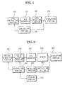
- FIG. 1 is a block diagram showing a conventional white balance regulating device.
- a conventional white balance regulating device comprises a level regulating portion 100, an A/D converter 110, a data detecting portion 120, a controlling portion 130 and a displaying portion 140.
- the level regulating portion 100 regulates the level of a variable register to set the cut-off point and the saturation point of the RGB colour signal input from the external apparatus.
- the A/D converter 110 converts an analogue RGB colour signal output from the level regulating portion 100 into a 24-bit digital signal comprising three 8-bit digital components corresponding to the R, G and B tristimulus values respectively.
- the data detecting portion 120 detects all the data bits of each 8-bit digital RGB colour signal.
- the controlling portion 130 compares all the data bits of each 8-bit digital RGB colour signal detected by the data detecting portion 120 with predetermined standard data, and then controls the level regulating portion 100 so as to regulate the variable register according to the result of the comparison.
- the displaying portion 140 receives a signal output from the data detecting portion 120, and drives a liquid crystal to display on a screen.
- the controlling portion 130 initialises the cut-off point to a desired data value 0x00 so as to regulate the cut-off point of the RGB colour signal input from the external apparatus. Furthermore, after initialising the cut-off point, the controlling portion 130 sets the variable register of the level regulating portion 100 to the desired value to perform a regulation of the cut-off point. The controlling portion 130 compares the 8-bit data of each RGB colour signal detected by the data detecting portion 120 with standard data.
- the controlling portion 130 controls the level regulating portion 100 to gradually increase the level of the variable register until obtaining an optimal cut-off point.
- the level regulating portion 100 regulates the level of the variable register according to a control signal of the controlling portion 130. If the 8-bit data of each RGB colour signal read through the regulated variable register of the level regulating portion 100 is larger than the standard data, the corresponding level of the variable register is set as the cut-off point.
- the saturation point is initialised to a desired data value 0xFF.
- the controlling portion 130 compares each RGB signal read through the data detecting portion 120 with the standard data.
- the controlling portion 130 controls the level regulating portion 100 to gradually reduce the level of the variable register until obtaining an optimal saturation point.
- the level regulating portion 100 regulates the level of the variable register according to a control signal of the controlling portion 130. If each data value corresponding to the RGB colour signal read through the regulated variable register of the level regulating portion 100 is smaller than the standard data, the corresponding level of the variable register is set as the saturation point.
- the data detecting portion 120 since the data detecting portion 120 has to read all the 8-bit digital data corresponding to each digital RGB colour signal output through the A/D converter 110, there is a problem that the circuit construction of the white balance regulating device becomes complicated.
- a white balance setting method is characterised by lowering the limit-level of each of the limiters until the least significant bit of its digitised output changes state.
- the level of each limiter is decremented in steps. More preferably, the method comprises storing the level which corresponds to the step preceding the one at which the least significant bit of the digitised output changes state, for each of the respective limiters.
- a white balance setting method is characterised by raising the limit-level of each of the limiters until the least significant bit of its digitised output changes state.
- the level of each limiter is incremented in steps. More preferably, the method comprises storing the level which corresponds to the step preceding the one at which the least significant bit of the digitised output changes state, for each of the respective limiters.
- a white balance setting method comprises both of the above-described white balance setting methods.
- a white balance regulating device comprises a pattern generating portion 200, a cut-off value adjusting portion 210, an A/D converter 220, a scaler 230, a rectifying filter 240, a detecting portion 250, a controlling portion 260, a storing portion 270 and a displaying portion 280.
- the pattern generating portion 200 generates an analogue image signal in the form of a first and second pattern according to a control signal of the controlling portion 260.
- the cut-off value adjusting portion 210 adjusts and outputs a cut-off value of the analogue image signal, which is input in the form of the first pattern.
- the first pattern is a black pattern
- the second pattern is a white pattern.
- the A/D converter 220 converts the analogue image signal output from the cut-off value adjusting portion 210 into a digital image signal.
- the scaler 230 transforms the digital image signal in a frame unit so as to display on a screen of the displaying portion 240.
- the rectifying filter 240 removes a noise component included in the digital image signal output through the scaler 230.
- the detecting portion 250 detects a least significant bit of each tristimulus value (e.g. R, G or B colour signal) of the digital image signal in which the noise component is removed by the rectifying filter 240.
- a least significant bit of each tristimulus value e.g. R, G or B colour signal
- the controlling portion 260 upwardly regulates the level of a variable register of the cut-off value adjusting portion 210 from a level corresponding to a preset first initial cut-off value until the least significant bit of the digital image signal changes from what it was when the register was set at the preset first initial cut-off value.
- the controlling portion 260 sets the level of the variable register, just before the least significant bit changes from what it was when the register was set at the preset first initial cut-off value, as a first cut-off value.
- the level of the variable register corresponding to the first initial cut-off value is 0x00.
- the first initial cut-off value does not have to be 0x00 and could be any value, provided that it is less than the predicted level of the cut-off point.
- the controlling portion 260 When the analogue image signal in the form of the second pattern is input to the cut-off value adjusting portion 210, the controlling portion 260 downwardly regulates the level of the variable register from a level corresponding to a preset second initial cut-off value until the least significant bit of the converted digital image signal changes from what it was when the register was set at the preset second initial cut-off value.
- the controlling portion 260 sets the level of the variable register, just before the least significant bit of the digital image signal changes from what it was when the register was set at the preset second initial cut-off value, as a second cut-off value.
- the level of the variable register corresponding to the second initial cut-off value is 0xFF.
- the first and second cut-off values are stored in the storing portion 270.
- the displaying portion 280 receives an RGB colour signal output from the scaler 230, and drives a liquid crystal to display on a screen.
- the first cut-off value means a cut-off point corresponding to the point at which light is about to be emitted
- the second cut-off value means a saturation point corresponding to the point at which the brightest light is emitted.
- the controlling portion 260 controls the pattern generating portion 200 to apply the analogue image signal input from an external apparatus in the form of the black pattern. Furthermore, the controlling portion 260 controls the cut-off value adjusting portion 210 to set the variable register of the cut-off value adjusting portion 210 to the first initial cut-off value.
- the pattern generating portion 200 applies the analogue image signal input from the external apparatus in the form of the black pattern according to a control signal of the controlling portion 260.
- the cut-off value adjusting portion 210 sets the level of the variable register to 0x00 according to the control signal of the controlling portion 260.
- the A/D converter 220 converts the analogue image signal output through the cut-off value adjusting portion 210 into an 8-bit digital image signal.
- R, G and B colour signals of the digital image data output through the A/D converter 220 are 8 bits respectively, and thus the combined RGB digital image signal is 24 bits in total.
- the scaler 230 transforms the digital image signal output through the A/D converter 220 in a frame unit so as to display on the screen of the displaying portion 240.
- the input image has to be transformed into a format which can be displayed on the digital display.
- the rectifying filter 240 removes a noise component included in the 8-bit digital image signal output through the scaler 230.
- the detecting portion 250 detects the 8-bit digital image signal, in which the noise component is removed, i.e. a least significant bit corresponding to each RGB colour signal. Furthermore, in the event of an error, the detecting portion 250 may detect a higher order bit, which is one step higher than the least significant bit, as well as the least significant bit corresponding to each 8-bit RGB colour signal output from the rectifying filter 240. Moreover, the detecting portion 250 can detect at least one bit out of four higher bits with respect to the 8-bit RGB colour signal.
- the controlling portion 260 compares the least significant bit corresponding to each RGB colour signal detected by the detecting portion 250 with the first initial cut-off value, and then upwardly regulates the level of the variable register of the cut-off value adjusting portion 210 from the level corresponding to the first initial cut-off value until the least significant bit of the digital image signal changes from what it was when the register was set at the preset first initial cut-off value.
- the controlling portion 260 sets the level of the variable register, just before the least significant bit of the digital image signal changes from what it was when the register was set at the preset first initial cut-off value, as the first cut-off value.
- the levels of the variable register just before the least significant bit is changed from 0 to 1, i.e. 0x4E, 0x52, 0x54 are set as the first cut-off value.
- the cut-off points 0x4E, 0x52, 0x54 with respect to each RGB colour signal are stored in the storing portion 270. Therefore, after setting the first cut-off value, the variable register of the cut-off value adjusting portion 210 is set to the first cut-off value corresponding to each RGB colour signal stored in the storing portion 270.
- the controlling portion 260 controls the pattern generating portion 200 to apply the analogue image signal input from the external apparatus in the form of the white pattern. Furthermore, the controlling portion 260 controls the cut-off value adjusting portion 210 to set the level of the variable register of the cut-off value adjusting portion 210 to the second initial cut-off value.
- the pattern generating portion 200 applies the analogue image signal input from the external apparatus in the form of the white pattern according to the control signal of the controlling portion 260.
- the cut-off value adjusting portion 210 sets the level of the variable register of the cut-off value adjusting portion 210 to the second initial cut-off value according to the control signal of the controlling portion 260.
- the level of the variable register corresponding to the second initial cut-off value is 0xFF.
- the second initial cut-off value does not have to be 0xFF and could be any value, provided that it is less than the predicted level of the saturation point.
- the A/D converter 220 converts the analogue image signal output from the cut-off value adjusting portion 210 into the 8-bit digital image signal.
- the scaler 230 transforms the digital image signal output from the A/D converter 220 in a frame unit so as to display on the screen.
- the rectifying filter 240 removes the noise component included in the 8-bit digital image signal output through the scaler 230.
- the detecting portion 250 detects the 8-bit digital image signal in which the noise component is removed by the rectifying portion 240, i.e. the least significant bit corresponding to each RGB colour signal is detected.
- the controlling portion 260 compares the least significant bit corresponding to each RGB colour signal detected by the detecting portion 250 with the second initial cut-off value, and then downwardly regulates the level of the variable register of the cut-off value adjusting portion 210 from 0xFF until the least significant bit of the digital image signal changes from what it was when the register was set at the preset second initial cut-off value.
- the controlling portion 260 sets the level of the variable register, just before the least significant bit of the digital image signal changes from what it was when the register was set at the preset second initial cut-off value, as the second cut-off value.
- the levels of the variable register just before the least significant bit is changed from 1 to 0, i.e. 0x55, 0x60, 0x73 are set as the second cut-off value.
- the points 0x55, 0x60, 0x73 are stored as the saturation points with respect to each RGB colour signal in the storing portion 270. Therefore, after setting the second cut-off value, the variable register of the cut-off value adjusting portion 210 is set to the second cut-off value corresponding to each RGB colour signal stored in the storing portion 270.
- the cut-off value adjusting portion 210 is divided into variable registers for respectively setting the first cut-off value and the second cut-off value.
- the controlling portion 260 in order to set the cut-off point of the analogue image signal input from the external apparatus, the controlling portion 260 initialises the level of the variable register of the cut-off regulating portion 210 to 0x00 (S300).
- the controlling portion 260 controls the pattern generating portion 200 to input the analogue image signal in the form of the black pattern.
- the pattern generating portion 200 applies the analogue image signal in the form of the black pattern according to the control signal of the controlling portion 260.
- the cut-off regulating portion 210 regulates and then outputs the cut-off value of the analogue image signal, which is input in the form of the black pattern.
- the A/D converter 220 converts the analogue image signal output from the cut-off regulating portion 210 into the digital image signal (S310).
- the scaler 230 transforms the digital image signal output through the A/D converter 220 to display on the screen of the displaying portion 280.
- the rectifying filter 240 removes the noise component included in the digital image signal output through the scaler 230.
- the detecting portion 250 detects the least significant bit corresponding to each RGB colour signal in which the noise component is removed.
- the controlling portion 260 compares the least significant bit corresponding to each RGB colour signal detected by the detecting portion 250 with its value when the register is set at 0x00 (S320).
- the controlling portion 260 upwardly regulates the level of the variable register of the cut-off regulating portion 210 (S330).
- the controlling portion 260 repeatedly performs the S330 process until the least significant bit of each RGB colour signal output from the S330 process changes from what it was when the register was set to the first initial cut-off value, i.e. until the least significant bit corresponding to each RGB colour signal detected by the detecting portion 250 is changed from 0 to 1 or from 1 to 0.
- the controlling portion 260 sets the level of the variable register just before the least significant bit is changed as the first cut-off value (S340).
- the controlling portion 260 initialises the level of the variable register of the cut-off value adjusting portion 210 to 0xFF in order to regulate the saturation point (S350).
- the controlling portion 260 controls the pattern generating portion 200 to input the analogue image signal from the external apparatus in the form of a white pattern.
- the pattern generating portion 200 applies the analogue image signal in the form of the white pattern according to the control signal of the controlling portion 260.
- the cut-off value adjusting portion 210 regulates and outputs the analogue image signal which is input in the form of the white pattern.
- the A/D converter 220 converts the analogue image signal output through the variable register into the digital image signal (S360).
- the scaler 230 transforms the digital image signal output through the A/D converter 220 to display on the screen of the displaying portion 280.
- the rectifying filter 240 removes the noise component included in the digital image signal output through the scaler 230.
- the detecting portion 250 detects the least significant bit corresponding to each RGB colour signal in which the noise component is removed by the rectifying filter 240.
- the controlling portion 260 compares the least significant bit corresponding to each RGB colour signal detected from the detecting portion 250 with its value when the register is set at 0xFF (S370).
- the controlling portion 260 downwardly regulates the level of the variable register of the cut-off value adjusting portion 210.
- the controlling portion 260 repeatedly performs the S380 process until the least significant bit of each RGB colour signal output through the S380 process changes from what it was when the register was set at the second initial cut-off value.
- the controlling portion 260 sets the level of the variable register, just before the least significant bit changes from what it was when the register was set at the second initial cut-off value, as the second cut-off value (S390). That is, the level of the variable register just before the least significant bit is changed from 1 to 0 or from 0 to 1, is set as the second cut-off value.
- variable register of the cut-off adjusting portion 210 is set to the first and the second cut-off value. Then, the analogue signal input from the external apparatus is converted into a digital value within a range from the first cut-off value to the second cut-off value set in the cut-off value adjusting portion 210.
- the white balance regulating device and the method thereof when the analogue image signal input from the external apparatus is converted into the digital image signal, the analogue signal is converted into the digital value within a displaying extent of the digital display. Therefore, a signal distortion phenomenon is prevented, whereby an image signal corresponding to a dark portion is cut off and thus is not displayed, or an image signal corresponding to a bright portion is saturated and thus is not displayed. Since the displaying extent of the digital display is maximised, quantisation loss can be minimized, and colour reproduction ability can be maximized.
- the white balance regulating device since the level of the variable register is regulated after the least significant bit corresponding to each RGB colour signal is detected, the white balance regulating device has a simple circuit construction and can be easily applied.
- the present invention can be applied to various display models in the same regulating method.
Landscapes
- Engineering & Computer Science (AREA)
- Physics & Mathematics (AREA)
- Computer Hardware Design (AREA)
- General Physics & Mathematics (AREA)
- Theoretical Computer Science (AREA)
- Multimedia (AREA)
- Signal Processing (AREA)
- Processing Of Color Television Signals (AREA)
- Control Of Indicators Other Than Cathode Ray Tubes (AREA)
- Color Television Image Signal Generators (AREA)
Abstract
Description
Claims (18)
- A white balance setting method comprising;
receiving an analogue component video signal generated from an optical reference white signal;
passing the components of the video signal through respective variable-level limiters; and
digitising the outputs of the limiters,
characterised by
lowering the limit-level of each of the limiters until the least significant bit of its digitised output changes state. - A method according to claim 1, wherein the level of each limiter is decremented in steps.
- A method according to claim 2, comprising storing the level which corresponds to the step preceding the one at which the least significant bit of the digitised output changes state, for each of the respective limiters.
- A white balance setting method comprising;
receiving an analogue component video signal generated from an optical reference black signal;
passing the components of the video signal through respective variable-level limiters; and
digitising the outputs of the limiters,
characterised by
raising the limit-level of each of the limiters until the least significant bit of its digitised output changes state. - A method according to claim 4, wherein the level of each limiter is incremented in steps.
- A method according to claim 5, comprising storing the level which corresponds to the step preceding the one at which the least significant bit of the digitised output changes state, for each of the respective limiters.
- A white balance setting method, comprising the methods of any one of claims 1, 2 or 3 and any one of claims 4, 5 or 6.
- A white balance regulating device, comprising:a cut-off value adjusting portion for adjusting and then outputting a cut-off value of an analog image signal which is input in the form of a first pattern;an A/D converter for converting the analog image signal, in which the cut-off value is adjusted, into a digital image signal;a detecting portion for detecting a least significant bit of each tristimulus value of the digital image signal;a controlling portion for upwardly regulating a level of a variable register of the cut-off value adjusting portion from a level corresponding to a preset first initial cut-off value until the least significant bit becomes different from the first initial cut-off value, and setting the level of the variable register just before the least significant bit becomes different from the first initial cut-off value as a first cut-off value; anda storing portion for storing the first cut-off value.
- The device of claim 8, wherein, when the analog image signal in the form of a second pattern is input to the cut-off value adjusting portion, the controlling portion downwardly regulates the level of the variable register from a level corresponding to a preset second initial cut-off value until the least significant bit becomes different from the second initial cut-off value, and sets a level of the variable register just before the least significant bit becomes different from the second initial cut-off value as a second cut-off value, and the second cut-off value is stored in the storing portion.
- The device of claim 9, further comprising a pattern generating portion for generating a first pattern and a second pattern with respect to the analog image signal, wherein the controlling portion controls the pattern generating portion to generate the first pattern when setting the first cut-off value and generate the second pattern when setting the second cut-off value.
- The device of claim 9, wherein the first pattern is a black pattern, and the second pattern is a white pattern.
- The device of claim 9, wherein the level of the variable register corresponding to the first initial cut-off value is 0x00, and the level of the variable register corresponding to the second initial cut-off value is 0xFF.
- The device of claim 8, further comprising a rectifying filter for removing a noise component included in the digital image signal output through the A/D converter, wherein the detecting portion detects the least significant bit of each tristimulus value of the digital image signal in which the noise component is removed.
- The device of claim 13, wherein the detecting portion detects a higher bit that is one step higher than the least significant bit of each tristimulus value of the digital image signal.
- A method of regulating a white balance, comprising:wherein the converting step to the upwardly regulating step is repeatedly performed until the least significant bit becomes different from the first initial cut-off value, and the level of the variable register just before the least significant bit becomes different from the first initial cut-off value is set as a first cut-off value.setting a level of a variable register to a level corresponding to a first initial cut-off value;adjusting and outputting through the variable register a cut-off value of an analog image signal which is input in the form of a first pattern;converting the cut-off value of the analog image signal output through the variable register into a digital image signal;comparing a least significant bit corresponding to each tristimulus value of the digital image signal with the first initial cut-off value; andupwardly regulating the level of the variable register,
- The method of claim 15, further comprising:wherein the converting step to the upwardly regulating step is repeatedly performed until the least significant bit becomes different from the second initial cut-off value, and the level of the variable register just before the least significant bit becomes different from the second initial cut-off value is set as a second cut-off value.setting the level of the variable register to a level corresponding to a second initial cut-off value;adjusting and outputting through the variable register the cut-off value of the analog signal which is input in the form of a second pattern;converting the cut-off value of the analog image signal output through the variable register into the digital image signal;comparing the least significant bit corresponding to each tristimulus value of the digital image signal with the second initial cut-off value; anddownwardly regulating the level of the variable register,
- The method of claim 16, wherein the first pattern is a black pattern, and the second pattern is a white pattern.
- The method of claim 16, wherein the level of the variable register corresponding to the first initial cut-off value is 0x00, and the level of the variable register corresponding to the second initial cut-off value is 0xFF.
Applications Claiming Priority (2)
| Application Number | Priority Date | Filing Date | Title |
|---|---|---|---|
| KR2002027934 | 2002-05-20 | ||
| KR10-2002-0027934A KR100441508B1 (en) | 2002-05-20 | 2002-05-20 | White balance controller and method thereof |
Publications (2)
| Publication Number | Publication Date |
|---|---|
| EP1365599A2 true EP1365599A2 (en) | 2003-11-26 |
| EP1365599A3 EP1365599A3 (en) | 2007-03-21 |
Family
ID=29398533
Family Applications (1)
| Application Number | Title | Priority Date | Filing Date |
|---|---|---|---|
| EP03253129A Withdrawn EP1365599A3 (en) | 2002-05-20 | 2003-05-20 | White balance setting method |
Country Status (4)
| Country | Link |
|---|---|
| US (1) | US7071998B2 (en) |
| EP (1) | EP1365599A3 (en) |
| KR (1) | KR100441508B1 (en) |
| CN (1) | CN1241418C (en) |
Families Citing this family (2)
| Publication number | Priority date | Publication date | Assignee | Title |
|---|---|---|---|---|
| US7616343B2 (en) * | 2006-04-06 | 2009-11-10 | Kabushiki Kaisha Toshiba | Image data conversion apparatus, image forming apparatus, image data conversion method and program |
| CN101227623B (en) * | 2008-01-31 | 2012-07-04 | 炬力集成电路设计有限公司 | White balance adjustment method, system and camera |
Family Cites Families (10)
| Publication number | Priority date | Publication date | Assignee | Title |
|---|---|---|---|---|
| US5258828A (en) * | 1989-11-13 | 1993-11-02 | Hitachi, Ltd. | Color CRT drive apparatus having automatic white balance adjusting circuit and CRT display |
| JPH0851643A (en) * | 1994-08-05 | 1996-02-20 | Matsushita Electric Ind Co Ltd | Adjustment control circuit and cut-off drive adjustment circuit and video equipment |
| JP3309593B2 (en) * | 1994-10-28 | 2002-07-29 | 松下電器産業株式会社 | Plasma display |
| US6285344B1 (en) * | 1998-03-13 | 2001-09-04 | Apple Computer, Inc. | Automatic adjustment of color balance and other display parameters in digital displays |
| KR100266166B1 (en) * | 1998-06-13 | 2000-09-15 | 구자홍 | Apparatus of adjusting white balance for plasma display panel |
| JP2000023181A (en) * | 1998-07-03 | 2000-01-21 | Hitachi Ltd | Display device for color video signal |
| KR100292535B1 (en) * | 1998-07-29 | 2001-06-01 | 구자홍 | Driving method and apparatus of plasma display device |
| JP3058176U (en) * | 1998-10-01 | 1999-06-08 | 船井電機株式会社 | Automatic white balance adjustment device |
| US6437833B1 (en) * | 1998-11-18 | 2002-08-20 | Kabushiki Kaisha Toshiba | Automatic white balance adjusting circuit in color image display |
| JP3541700B2 (en) * | 1998-12-25 | 2004-07-14 | 日本ビクター株式会社 | Video signal adjusting circuit and method for matrix display device |
-
2002
- 2002-05-20 KR KR10-2002-0027934A patent/KR100441508B1/en not_active Expired - Fee Related
-
2003
- 2003-03-28 CN CNB031085121A patent/CN1241418C/en not_active Expired - Fee Related
- 2003-05-15 US US10/438,011 patent/US7071998B2/en not_active Expired - Fee Related
- 2003-05-20 EP EP03253129A patent/EP1365599A3/en not_active Withdrawn
Also Published As
| Publication number | Publication date |
|---|---|
| EP1365599A3 (en) | 2007-03-21 |
| KR20030089993A (en) | 2003-11-28 |
| KR100441508B1 (en) | 2004-07-23 |
| US7071998B2 (en) | 2006-07-04 |
| US20030214606A1 (en) | 2003-11-20 |
| CN1459983A (en) | 2003-12-03 |
| CN1241418C (en) | 2006-02-08 |
Similar Documents
| Publication | Publication Date | Title |
|---|---|---|
| US8537085B2 (en) | Method and apparatus for adjusting quality of a displayed image | |
| EP0966165B1 (en) | Video signal processing circuit providing optimum signal level for inverse gamma correction | |
| JP3719411B2 (en) | Image display system, projector, program, information storage medium, and image processing method | |
| JP4277773B2 (en) | Video display device | |
| CN100397909C (en) | Video signal processing circuit, video display device, and video display method | |
| US7110046B2 (en) | Method for dynamically adjusting video brightness | |
| KR100911815B1 (en) | Contrast control method, signal processing device, display device and computer readable medium | |
| EP2227032B1 (en) | Brightness information display and method | |
| US20130285890A1 (en) | Display device | |
| EP1365599A2 (en) | White balance setting method | |
| JP2008065185A (en) | Display controller, display device, display system, and display control method | |
| JP4758999B2 (en) | Image processing program, image processing method, and image processing apparatus | |
| JPH1173162A (en) | Simultaneous brightness and contrast adjustment circuit for LCD monitor | |
| JP4831173B2 (en) | Video display device | |
| JP4470587B2 (en) | Image display device | |
| US20200251069A1 (en) | Color image display adaptation to ambient light | |
| JP3714877B2 (en) | Image display device and program | |
| KR100438280B1 (en) | Apparatus and Method for controlling a White Balance of OSD Screen | |
| KR100771618B1 (en) | Color adjustment device and method | |
| CN1857010A (en) | Saturation correction for color pictures | |
| JP2000075838A (en) | Color liquid crystal display | |
| KR20050056782A (en) | Automatical white balance adjustment apparatus | |
| JP4289156B2 (en) | Video signal correction device | |
| JP2001209348A (en) | Digital panel display | |
| JPH06326942A (en) | Method and device for controlling electronic display |
Legal Events
| Date | Code | Title | Description |
|---|---|---|---|
| PUAI | Public reference made under article 153(3) epc to a published international application that has entered the european phase |
Free format text: ORIGINAL CODE: 0009012 |
|
| AK | Designated contracting states |
Kind code of ref document: A2 Designated state(s): AT BE BG CH CY CZ DE DK EE ES FI FR GB GR HU IE IT LI LU MC NL PT RO SE SI SK TR |
|
| AX | Request for extension of the european patent |
Extension state: AL LT LV MK |
|
| RAP1 | Party data changed (applicant data changed or rights of an application transferred) |
Owner name: SAMSUNG ELECTRONICS CO., LTD. |
|
| PUAL | Search report despatched |
Free format text: ORIGINAL CODE: 0009013 |
|
| AK | Designated contracting states |
Kind code of ref document: A3 Designated state(s): AT BE BG CH CY CZ DE DK EE ES FI FR GB GR HU IE IT LI LU MC NL PT RO SE SI SK TR |
|
| AX | Request for extension of the european patent |
Extension state: AL LT LV MK |
|
| 17P | Request for examination filed |
Effective date: 20070601 |
|
| AKX | Designation fees paid |
Designated state(s): DE FR GB |
|
| 17Q | First examination report despatched |
Effective date: 20080219 |
|
| RAP1 | Party data changed (applicant data changed or rights of an application transferred) |
Owner name: SAMSUNG ELECTRONICS CO., LTD. |
|
| STAA | Information on the status of an ep patent application or granted ep patent |
Free format text: STATUS: THE APPLICATION IS DEEMED TO BE WITHDRAWN |
|
| 18D | Application deemed to be withdrawn |
Effective date: 20141202 |