EP1365544A1 - Bridge element enabled module and method - Google Patents
Bridge element enabled module and method Download PDFInfo
- Publication number
- EP1365544A1 EP1365544A1 EP03011314A EP03011314A EP1365544A1 EP 1365544 A1 EP1365544 A1 EP 1365544A1 EP 03011314 A EP03011314 A EP 03011314A EP 03011314 A EP03011314 A EP 03011314A EP 1365544 A1 EP1365544 A1 EP 1365544A1
- Authority
- EP
- European Patent Office
- Prior art keywords
- bridge element
- module
- protocol
- host
- communication infrastructure
- Prior art date
- Legal status (The legal status is an assumption and is not a legal conclusion. Google has not performed a legal analysis and makes no representation as to the accuracy of the status listed.)
- Granted
Links
Images

Classifications
-
- H—ELECTRICITY
- H04—ELECTRIC COMMUNICATION TECHNIQUE
- H04L—TRANSMISSION OF DIGITAL INFORMATION, e.g. TELEGRAPHIC COMMUNICATION
- H04L12/00—Data switching networks
- H04L12/28—Data switching networks characterised by path configuration, e.g. LAN [Local Area Networks] or WAN [Wide Area Networks]
- H04L12/46—Interconnection of networks
- H04L12/4604—LAN interconnection over a backbone network, e.g. Internet, Frame Relay
- H04L12/462—LAN interconnection over a bridge based backbone
-
- G—PHYSICS
- G06—COMPUTING OR CALCULATING; COUNTING
- G06F—ELECTRIC DIGITAL DATA PROCESSING
- G06F13/00—Interconnection of, or transfer of information or other signals between, memories, input/output devices or central processing units
- G06F13/38—Information transfer, e.g. on bus
- G06F13/40—Bus structure
- G06F13/4004—Coupling between buses
- G06F13/4027—Coupling between buses using bus bridges
Definitions
- Coupled may be used to indicate that two or more elements are in direct physical or electrical contact.
- coupled may mean that two or more elements are not in direct contact with each other, but yet still co-operate or interact with each other.
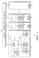
- FIG. 1 depicts a multi-service platform system 100 according to one embodiment of the invention.
- a multi-service platform system 100 can include one or more computer chassis, with software and any number of slots for inserting modules. Modules can add functionality to multi-service platform system 100 through the addition of processors, memory, storage devices, and the like. In one embodiment a backplane connector is used for connecting modules placed in the slots.
- a multi-service platform system can include model MVME5100 manufactured by Motorola Computer Group, 2900 South Diablo Way, Tempe, AZ 85282. The invention is not limited to this model or manufacturer and any multi-service platform system is included within the scope of the invention.
- Multi-service platform system 100 can include any number of modules coupled to intermodule communication infrastructure 104.
- Modules can include bridge element enabled module 102, first module 114, second module 116 and any number of other modules supported in the chassis as represented by the Xth module 126.
- Intermodule communication infrastructure 104 can include hardware and software necessary to implement a high-speed data network using parallel multi-drop or switched point-to-point topologies and protocols.
- An example of a parallel multi-drop topology is a VERSAmodule Eurocard (VMEbus) system using any of the VMEbus protocols known in the art.
- VMEbus VERSAmodule Eurocard
- Multi-service platform system 100 is controlled by a platform controller (not shown for clarity), which can include a processor for processing algorithms stored in memory.
- Memory comprises control algorithms, and can include, but is not limited to, random access memory (RAM), read only memory (ROM), flash memory, electrically erasable programmable ROM (EEPROM), and the like.
- Memory can contain stored instructions, tables, data, and the like, to be utilized by processor.
- Platform controller can be contained in one, or distributed among two or more modules with communication among the various modules of multi-service platform system 100 occurring via intermodule communication infrastructure 104. Platform controller also controls the functionality of multi-service platform system 100 including managing any modules placed in the slots of the chassis to add functionality to the multi-service platform system 100.
- Bridge element enabled module 102 includes bridge element 106, which can be hardware and/or software to provide an interface between host elements on the bridge element enabled module 102 and intermodule communication infrastructure 104.
- Bridge element enabled module 102 can include any number of host elements, for example first host element 108, second host element 110, and any number of other host elements as represented by the Xth host element 112. Each host element is coupled to communicate with bridge element 106.
- Bridge element 106 is coupled to communicate with intermodule communication infrastructure 104.
- Host elements can include, without limitation, processors, memory modules, storage devices, input/output (I/O) devices, and the like.
- host elements are coupled to bridge element 106 and communicate with bridge element 106 through a parallel multi-drop network, which can use for example, a Peripheral Interconnect-X (PCI-X) based protocol 128.
- PCI-X based protocols 128 can include both PCI and PCI-X2 protocols.
- Bridge element 106 is capable of communicating with first host element 108, second host element 110 and Xth host element 112 using any variant of the PCI-X based protocol 128. Examples of variants of PCI-X protocols 128, without limitation, include 133 MHz 64-bit PCI-X, 100 MHz 64-bit PCI-X down to 66 MHz 32-bit PCI-X, and the like.
- Bridge element 106 can also communicate with first host element 108, second host element 110 and Xth host element 112 using any variant of older PCI based protocols (a subset of PCI-X based protocols 128), for example and without limitation, 66 MHz 64-bit PCI down to 33 MHz 32-bit PCI, and the like.
- Bridge element 106 allows bridge element enabled module 102 to communicate with first module 114, second module 116 and Xth module 126 via the intermodule communication infrastructure 104 using protocol 130.
- bridge element 106 uses a protocol 130 selected from group of protocols 105, which can include any of the VMEbus based protocols.
- VMEbus based protocols can include, but are not limited to, Single Cycle Transfer protocol (SCT), Block Transfer protocol (BLT), Multiplexed Block Transfer protocol (MBLT), Two Edge VMEbus protocol (2eVME) and Two Edge Source Synchronous Transfer protocol (2eSST). These VMEbus protocols are known in the art.
- First module 114 can have one or more host elements analogous to those described above for bridge element enabled module 102, one of which is represented by first module host element 118. First module 114 can also be configured with a bridge element thereby becoming bridge element enabled (as represented in FIG. 1 by including dashed box 122). First module 114 can also lack a bridge element (by not including dashed box 122), and be non-bridge element enabled. The significance of being bridge element enabled and non-bridge element enabled is discussed with reference to FIG.4 below. Analogously, second module 116 includes any number of host elements as represented by second module host element 120 and can be either bridge element enabled (by including dashed box 124) or non-bridge element enabled (by not including dashed box 124).
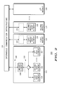
- FIG.2 depicts a multi-service platform system 200 according to another embodiment of the invention.
- bridge element enabled module 102 includes a switched point-to-point protocol 132 and network coupling first host element 108, second host element 110 and Xth host element 112 to bridge element 106.
- Switched point-to-point protocol 132 can include, for example and without limitation, RapidIO, Serial RapidIO, 3GIO, Infiniband, Hypertransport, and the like.
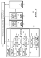
- FIG.3 depicts a multi-service platform system 300 according to yet another embodiment of the invention.
- bridge element 106 is shown coupled to host bus 372, where host bus 372 represents either parallel multi-drop bus with PCI-X protocol 128 of FIG. 1 or switched point-to-point protocol 132 of FIG.2.
- Xth host element 112 has been omitted from FIG.3 for clarity.
- bridge element 106 can communicate with first host element 108 and second host element 110 using either PCI-X based protocol 128 or switched point-to-point protocol 132 depending on the design of the host side of bridge element enabled module 102. Either topology along with its associated protocols is within the scope of the invention.
- Linkage 350 is used to interconnect functions provided by bridge element 106 and provide a common interface for other elements of bridge element 106.
- linkage 350 has five ports including VMEbus, Host bus, two Direct Memory Access (DMA) controller ports, and one memory port.
- the number of ports for linkage 350 is not limiting of the invention and a linkage 350 with any number of ports is within the scope of the invention.
- the host master 358 and host slave 356 can be hardware and/or software elements that operate to interface host bus 372 to intermodule communication infrastructure 104 and its associated group of protocols 105.
- host master 358 and host slave 356 can be PCI master and PCI slave respectively when host bus 372 uses a PCI-X based protocol 128.
- host master 358 and host slave 356 can be switched point-to-point master and slave respectively when host bus 372 uses switched point-to-point protocol 132.
- host slave 356 when host bus 372 uses PCI-X based protocol 128, host slave 356 is responsible for tracking and maintaining coherency to the host bus 372 protocols, which can include PCI-X based protocols, 32-bit and 64-bit data transfers and 32-bit and 64-bit addresses.
- the host slave 356 supports configuration cycles to PCI configuration registers and memory space access, through first-in-first-out (FIFO) methodology to linkage 350.
- Host master 358 provides the interface between linkage 350 and host bus 372.
- Host master 358 in this embodiment supports PCI-X based protocols, 32-bit and 64-bit data bus and 32-bit and 64-bit address bus.
- the VMEbus master 352 and VMEbus slave 354 can be hardware and/or software elements that operate to interface intermodule communication infrastructure 104 to host bus 372 and it's associated protocols.
- the VMEbus slave tracks and maintains coherency to the group of protocols 105, which can be VMEbus protocols.
- VMEbus slave 354 supports SCT, BLT, MBLT, 2eVME and 2eSST protocols.
- VMEbus master 352 provides the interface between linkage 350 and intermodule communication infrastructure 104, which can be a VMEbus.
- VMEbus master 352 also supports SCT, BLT, MBLT, 2eVME and 2eSST protocols.
- Memory 364 is coupled to linkage 350, and can include, but is not limited to, random access memory (RAM), read only memory (ROM), flash memory, electrically erasable programmable ROM (EEPROM), and the like. Memory 364 can contain stored instructions, tables, data, and the like, to be utilized by a processor (not shown for clarity). In an embodiment of the invention, memory 364 can comprise control registers for bridge element 106. Control registers can include, for example and without limitation, PCI Configuration Space registers (PCFS), Local Control and Status registers (LCSR), Global Control and Status registers (GCSR) and Configuration Control and Status registers (CR/CSR).
- PCFS PCI Configuration Space registers
- LCSR Local Control and Status registers
- GCSR Global Control and Status registers
- CSR Configuration Control and Status registers
- PCFS registers are PCI registers defined in the PCI standards.
- LCSR registers contain control and status registers, which include inbound and outbound map decoder registers, DMA controller registers, interrupt control registers.
- GCSR registers include control bits, which allow information to be passed between host elements on other modules and first host element 108 on bridge element enabled module 102.
- CR/CSR registers are defined in the VME64 standard.
- Location monitor 366 is coupled to location interface 367.
- Location interface 367 communicates the location 368 of bridge element enabled module 102 within multi-service platform system 100 to location monitor 366 on bridge element 106.
- Location interface 367 can be, for example, module slot identification pins.
- location interface 367 communicates the location 368 of bridge element enabled module 102 to bridge element 106 via location monitor 366.
- Bridge element 106 further communicates location 368 to the platform controller of multi-service platform system 300 via intermodule communication infrastructure 104.
- platform controller of multi-service platform system 300 knows that a specific type of bridge element enabled module 102 is located in a particular slot of multi-service platform system 100.
- bridge element 106 can also broadcast location 368 of bridge element enabled module 102 directly to other modules in multi-service platform system 300, such as first module 114, second module 116 and Xth module 126.
- bridge element 106 has DMA controllers 360, 362.
- DMA controllers 360, 362 can move data among host elements of multi-service platform system 300 without intervention by a processor (not shown for clarity). With the processor freed from involvement in the data transfer, overall the speed of multi-service platform system 300 is increased.
- bridge element 106 has two DMA controllers 360, 362.
- any number of DMA controllers is within the scope of the invention.
- either one of DMA controllers 360, 362 can perform the functions listed below.
- DMA controllers 360, 362 there are two operating modes for DMA controllers 360, 362: direct mode and linked-list mode.
- direct mode DMA controllers 360, 362 are programmed directly by a processor (not shown), with the data subsequently transferred per the commands programmed by the processor.
- linked-list mode DMA controllers 360, 362 execute a list of commands stored in memory 364. The list of commands can be retrieved using the host bus and executed on a FIFO basis. If DMA controllers 360, 362 are to transfer data using the intermodule communication infrastructure 104, each of the commands to transfer data includes a protocol 130 to be selected from group of protocols 105 for data transfer on the intermodule communication infrastructure 104.
- bridge element 106 selects protocol 130 from group of protocols 105 in order to transfer data over the intermodule communication infrastructure 104.
- Protocol 130 can be selected to correspond to any other module in multi-service platform system 300 to which bridge element enabled module 102 is to transfer data.
- the selection of a protocol can be based on the capabilities of the module that data is to be transferred to. For example, if first module 114 is to receive data from DMA controllers 360, 362, and first module 114 can only communicate using BLT protocol, then DMA controllers 360, 362 and bridge element 106 can transfer data using BLT protocol.
- DMA controllers 360, 362 can transfer data among the various host elements of multi-service platform system 300.
- DMA controllers 360, 362 can move data between first host element 108 and second host element 110 on bridge element enabled module 102.
- first host element 108 and second host element 110 can move data between each other using DMA controllers 360, 362 on bridge element 106. This has particular application when first host element 108 and second host element 110 do not have their own DMA controllers.
- DMA controllers 360, 362 can move data between first host element 108 and first module host element 118.
- bridge element 106 can include in the command to transfer data, protocol 130 selected from group of protocols 105 for moving data over intermodule communication infrastructure 104. Protocol 130 can be selected to correspond to a VMEbus protocol used by first module 114 as described above.
- DMA controllers 360, 362 can move data between first module 114 and second module 116. In effect, data is moved between first module 114 and second module 116 using DMA controllers 360, 362 located on bridge element 106 within bridge element enabled module 102.
- bridge element 106 can select protocol 130 from group of protocols 105 to move data between first module 114 and second module 116. Protocol 130 can be selected to correspond to a VMEbus protocol used by both first module 114 and second module 116. This operation is particularly advantageous where neither first module 114 nor second module 116 has their own DMA controllers.
- DMA controllers 360, 362 can be used to move data between two host elements on a module other than bridge element enabled module 102.
- FIG.4 depicts a multi-service platform system 400 according to still another embodiment of the invention.
- bridge element enabled module 102 can communicate with first module 114 via intermodule communication infrastructure 104, with first module 114 having either of two different configurations.
- First module 114 can be either bridge element enabled as represented by the inclusion of dashed box 122, or non-bridge element enabled as represented by a lack of dashed box 122.
- Bridge element enabled can mean that first module 114 includes a bridge element analogous to bridge element 106 included with bridge element enabled module 102.
- Non-bridge element enabled can mean that first module 114 does not include a bridge element in its architecture. This generally includes older modules installed in multi-service platform system 400 known as legacy modules.
- Bridge element 106 of bridge element enabled module 102 operates to communicate with intermodule communication infrastructure 104, including first module 114, using protocol 130 selected from group of protocols 105 including the 2eSST protocol 480. If first module 114 is bridge element enabled, then bridge element enabled module 102 communicates with first module 114 via intermodule communication infrastructure 104 using 2eSST protocol 480. In other words, bridge element 106 selects 2eSST protocol 480 from group of protocols 105 to use in communication between bridge element enabled module 102 and first module 114.
- bridge element enabled module 102 communicates with first module 114 via intermodule communication infrastructure 104 using protocol selected to correspond to first module 482.
- bridge element 106 selects protocol from group of protocols 105 to use in communication between bridge element enabled module 102 and first module 114.
- Protocol selected to correspond to first module 482 can include any VMEbus protocol used by first module 114.
- protocol selected to correspond to first module 482 can include any VMEbus protocol that first module 114 is designed to use, which generally includes VMEbus protocols older than 2eSST, for example and without limitation, SCT, BLT, MBLT and 2eVME protocols.
- a protocol can be selected such that data transfer occurs in any other optimal manner, such as fast, efficient, and the like.
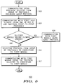
- FIG. 5 illustrates a flow diagram 500 of a method of the invention according to an embodiment of the invention.
- bridge element 106 coupled to bridge element enabled module 102 is communicating with intermodule communication infrastructure 104 using protocol 130 selected from group of protocols 105 including 2eSST protocol 480.
- Bridge element can also communicate with other modules of multi-service platform system 100, such as first module 114 and second module 116 using protocol 130 selected from group of protocols 105 including 2eSST protocol 480.
- bridge element 106 is communicating with first host element 108 that is coupled to bridge element 106 using one of a PCI-X based protocol 128 and a switched point-to-point protocol 132.
- step 506 it is determined if first module 114 is bridge element enabled. If so, bridge element 106 communicates with first module 114 via intermodule communication infrastructure 104 using 2eSST protocol 480 per step 508. If first module 114 is non-bridge element enabled, then bridge element 106 selects protocol from group of protocols to correspond to first module 482 per step 510. Then bridge element 106 communicates with first module 114 via intermodule communication infrastructure 104 using the protocol selected to correspond to the first module 482 per step 512. As described above, protocol selected to correspond to first module 482 can be a VMEbus protocol selected to correspond to a VMEbus protocol used by first module 114.
Landscapes
- Engineering & Computer Science (AREA)
- General Engineering & Computer Science (AREA)
- Theoretical Computer Science (AREA)
- General Physics & Mathematics (AREA)
- Computer Hardware Design (AREA)
- Physics & Mathematics (AREA)
- Signal Processing (AREA)
- Computer Networks & Wireless Communication (AREA)
- Bus Control (AREA)
- Measuring Fluid Pressure (AREA)
- Mobile Radio Communication Systems (AREA)
- Communication Control (AREA)
- Computer And Data Communications (AREA)
Abstract
Description
- In current high-speed data networks, such as multi-service platform systems, numerous protocols are used on the host and on the network side of individual modules. In such systems, it is desirable to move large amounts of data between modules with maximum speed and efficiency while maintaining compatibility between newer modules and older modules. In prior art multi-service platform systems, bridging elements between host and network side of the modules bridged primarily the Peripheral Component Interconnect PCI protocol on the host side and older versions of VERSAmodule Eurocard (VMEbus) protocols on the network side. With newer protocols available on both the host and network side, more efficient and versatile bridging elements are desirable. In addition, prior art bridging chips are not always backward compatible to support legacy module devices and protocols found in many multi-service platform systems.
- Accordingly, there is a significant need for an apparatus and method that overcomes the deficiencies of the prior art outlined above.
- Referring to the drawing:
- FIG. 1 depicts a multi-service platform system according to one embodiment of the invention;
- FIG. 2 depicts a multi-service platform system according to another embodiment of the invention;
- FIG.3 depicts a multi-service platform system according to yet another embodiment of the invention;
- FIG.4 depicts a multi-service platform system according to still another embodiment of the invention; and
- FIG. 5 illustrates a flow diagram of a method of the invention according to an embodiment of the invention.
-
- It will be appreciated that for simplicity and clarity of illustration, elements shown in the drawing have not necessarily been drawn to scale. For example, the dimensions of some of the elements are exaggerated relative to each other. Further, where considered appropriate, reference numerals have been repeated among the Figures to indicate corresponding elements.
- In the following detailed description of exemplary embodiments of the invention, reference is made to the accompanying drawings, which illustrate specific exemplary embodiments in which the invention may be practiced. These embodiments are described in sufficient detail to enable those skilled in the art to practice the invention, but other embodiments may be utilized and logical, mechanical, electrical and other changes may be made without departing from the scope of the present invention. The following detailed description is, therefore, not to be taken in a limiting sense, and the scope of the present invention is defined only by the appended claims.
- In the following description, numerous specific details are set forth to provide a thorough understanding of the invention. However, it is understood that the invention may be practiced without these specific details. In other instances, well-known circuits, structures and techniques have not been shown in detail in order not to obscure the invention.
- In the following description and claims, the terms "coupled" and "connected," along with their derivatives, may be used. It should be understood that these terms are not intended as synonyms for each other. Rather, in particular embodiments, "connected" may be used to indicate that two or more elements are in direct physical or electrical contact. However, "coupled" may mean that two or more elements are not in direct contact with each other, but yet still co-operate or interact with each other.
- For clarity of explanation, the embodiments of the present invention are presented, in part, as comprising individual functional blocks. The functions represented by these blocks may be provided through the use of either shared or dedicated hardware, including, but not limited to, hardware capable of executing software. The present invention is not limited to implementation by any particular set of elements, and the description herein is merely representational of one embodiment.
- FIG. 1 depicts a
multi-service platform system 100 according to one embodiment of the invention. Amulti-service platform system 100 can include one or more computer chassis, with software and any number of slots for inserting modules. Modules can add functionality tomulti-service platform system 100 through the addition of processors, memory, storage devices, and the like. In one embodiment a backplane connector is used for connecting modules placed in the slots. As an example of an embodiment, a multi-service platform system can include model MVME5100 manufactured by Motorola Computer Group, 2900 South Diablo Way, Tempe, AZ 85282. The invention is not limited to this model or manufacturer and any multi-service platform system is included within the scope of the invention. -
Multi-service platform system 100 can include any number of modules coupled tointermodule communication infrastructure 104. Modules can include bridge element enabledmodule 102,first module 114,second module 116 and any number of other modules supported in the chassis as represented by theXth module 126.Intermodule communication infrastructure 104 can include hardware and software necessary to implement a high-speed data network using parallel multi-drop or switched point-to-point topologies and protocols. An example of a parallel multi-drop topology is a VERSAmodule Eurocard (VMEbus) system using any of the VMEbus protocols known in the art. -
Multi-service platform system 100 is controlled by a platform controller (not shown for clarity), which can include a processor for processing algorithms stored in memory. Memory comprises control algorithms, and can include, but is not limited to, random access memory (RAM), read only memory (ROM), flash memory, electrically erasable programmable ROM (EEPROM), and the like. Memory can contain stored instructions, tables, data, and the like, to be utilized by processor. Platform controller can be contained in one, or distributed among two or more modules with communication among the various modules ofmulti-service platform system 100 occurring viaintermodule communication infrastructure 104. Platform controller also controls the functionality ofmulti-service platform system 100 including managing any modules placed in the slots of the chassis to add functionality to themulti-service platform system 100. - Bridge element enabled
module 102 includesbridge element 106, which can be hardware and/or software to provide an interface between host elements on the bridge element enabledmodule 102 andintermodule communication infrastructure 104. Bridge element enabledmodule 102 can include any number of host elements, for examplefirst host element 108,second host element 110, and any number of other host elements as represented by theXth host element 112. Each host element is coupled to communicate withbridge element 106.Bridge element 106 is coupled to communicate withintermodule communication infrastructure 104. Host elements can include, without limitation, processors, memory modules, storage devices, input/output (I/O) devices, and the like. - In the embodiment shown in FIG. 1, host elements are coupled to
bridge element 106 and communicate withbridge element 106 through a parallel multi-drop network, which can use for example, a Peripheral Interconnect-X (PCI-X) basedprotocol 128. In an embodiment of the invention, PCI-X basedprotocols 128 can include both PCI and PCI-X2 protocols.Bridge element 106 is capable of communicating withfirst host element 108,second host element 110 andXth host element 112 using any variant of the PCI-X basedprotocol 128. Examples of variants of PCI-X protocols 128, without limitation, include 133 MHz 64-bit PCI-X, 100 MHz 64-bit PCI-X down to 66 MHz 32-bit PCI-X, and the like.Bridge element 106 can also communicate withfirst host element 108,second host element 110 andXth host element 112 using any variant of older PCI based protocols (a subset of PCI-X based protocols 128), for example and without limitation, 66 MHz 64-bit PCI down to 33 MHz 32-bit PCI, and the like. -
Bridge element 106 allows bridge element enabledmodule 102 to communicate withfirst module 114,second module 116 andXth module 126 via theintermodule communication infrastructure 104 usingprotocol 130. In an embodiment of the invention,bridge element 106 uses aprotocol 130 selected from group ofprotocols 105, which can include any of the VMEbus based protocols. In an embodiment of the invention, VMEbus based protocols can include, but are not limited to, Single Cycle Transfer protocol (SCT), Block Transfer protocol (BLT), Multiplexed Block Transfer protocol (MBLT), Two Edge VMEbus protocol (2eVME) and Two Edge Source Synchronous Transfer protocol (2eSST). These VMEbus protocols are known in the art. -
First module 114 can have one or more host elements analogous to those described above for bridge element enabledmodule 102, one of which is represented by firstmodule host element 118.First module 114 can also be configured with a bridge element thereby becoming bridge element enabled (as represented in FIG. 1 by including dashed box 122).First module 114 can also lack a bridge element (by not including dashed box 122), and be non-bridge element enabled. The significance of being bridge element enabled and non-bridge element enabled is discussed with reference to FIG.4 below. Analogously,second module 116 includes any number of host elements as represented by secondmodule host element 120 and can be either bridge element enabled (by including dashed box 124) or non-bridge element enabled (by not including dashed box 124). - FIG.2 depicts a
multi-service platform system 200 according to another embodiment of the invention. As shown in FIG.2, bridge element enabledmodule 102 includes a switched point-to-point protocol 132 and network couplingfirst host element 108,second host element 110 andXth host element 112 to bridgeelement 106. Switched point-to-point protocol 132can include, for example and without limitation, RapidIO, Serial RapidIO, 3GIO, Infiniband, Hypertransport, and the like. - FIG.3 depicts a
multi-service platform system 300 according to yet another embodiment of the invention. As shown in FIG.3,bridge element 106 is shown coupled tohost bus 372, wherehost bus 372 represents either parallel multi-drop bus with PCI-X protocol 128 of FIG. 1 or switched point-to-point protocol 132 of FIG.2.Xth host element 112 has been omitted from FIG.3 for clarity. In other words,bridge element 106 can communicate withfirst host element 108 andsecond host element 110 using either PCI-X basedprotocol 128 or switched point-to-point protocol 132 depending on the design of the host side of bridge element enabledmodule 102. Either topology along with its associated protocols is within the scope of the invention. - Also shown in FIG.3 are various components of
bridge element 106.Linkage 350 is used to interconnect functions provided bybridge element 106 and provide a common interface for other elements ofbridge element 106. In one embodiment of the invention,linkage 350 has five ports including VMEbus, Host bus, two Direct Memory Access (DMA) controller ports, and one memory port. The number of ports forlinkage 350 is not limiting of the invention and alinkage 350 with any number of ports is within the scope of the invention. - The
host master 358 andhost slave 356 can be hardware and/or software elements that operate to interfacehost bus 372 tointermodule communication infrastructure 104 and its associated group ofprotocols 105. In one embodiment,host master 358 andhost slave 356 can be PCI master and PCI slave respectively whenhost bus 372 uses a PCI-X basedprotocol 128. In another embodiment,host master 358 andhost slave 356 can be switched point-to-point master and slave respectively whenhost bus 372 uses switched point-to-point protocol 132. - In an example of an embodiment of the invention, when
host bus 372 uses PCI-X basedprotocol 128,host slave 356 is responsible for tracking and maintaining coherency to thehost bus 372 protocols, which can include PCI-X based protocols, 32-bit and 64-bit data transfers and 32-bit and 64-bit addresses. Thehost slave 356 supports configuration cycles to PCI configuration registers and memory space access, through first-in-first-out (FIFO) methodology tolinkage 350.Host master 358 provides the interface betweenlinkage 350 andhost bus 372.Host master 358 in this embodiment supports PCI-X based protocols, 32-bit and 64-bit data bus and 32-bit and 64-bit address bus. - The
VMEbus master 352 andVMEbus slave 354 can be hardware and/or software elements that operate to interfaceintermodule communication infrastructure 104 to hostbus 372 and it's associated protocols. The VMEbus slave tracks and maintains coherency to the group ofprotocols 105, which can be VMEbus protocols.VMEbus slave 354 supports SCT, BLT, MBLT, 2eVME and 2eSST protocols.VMEbus master 352 provides the interface betweenlinkage 350 andintermodule communication infrastructure 104, which can be a VMEbus.VMEbus master 352 also supports SCT, BLT, MBLT, 2eVME and 2eSST protocols. -
Memory 364 is coupled tolinkage 350, and can include, but is not limited to, random access memory (RAM), read only memory (ROM), flash memory, electrically erasable programmable ROM (EEPROM), and the like.Memory 364 can contain stored instructions, tables, data, and the like, to be utilized by a processor (not shown for clarity). In an embodiment of the invention,memory 364 can comprise control registers forbridge element 106. Control registers can include, for example and without limitation, PCI Configuration Space registers (PCFS), Local Control and Status registers (LCSR), Global Control and Status registers (GCSR) and Configuration Control and Status registers (CR/CSR). - PCFS registers are PCI registers defined in the PCI standards. LCSR registers contain control and status registers, which include inbound and outbound map decoder registers, DMA controller registers, interrupt control registers. GCSR registers include control bits, which allow information to be passed between host elements on other modules and
first host element 108 on bridge element enabledmodule 102. CR/CSR registers are defined in the VME64 standard. -
Location monitor 366 is coupled tolocation interface 367.Location interface 367 communicates thelocation 368 of bridge element enabledmodule 102 withinmulti-service platform system 100 to location monitor 366 onbridge element 106.Location interface 367 can be, for example, module slot identification pins. When bridge element enabledmodule 102 is placed in a slot inmulti-service platform system 100,location interface 367 communicates thelocation 368 of bridge element enabledmodule 102 to bridgeelement 106 vialocation monitor 366.Bridge element 106 further communicateslocation 368 to the platform controller ofmulti-service platform system 300 viaintermodule communication infrastructure 104. As such, platform controller ofmulti-service platform system 300 knows that a specific type of bridge element enabledmodule 102 is located in a particular slot ofmulti-service platform system 100. In another embodiment of the invention,bridge element 106 can also broadcastlocation 368 of bridge element enabledmodule 102 directly to other modules inmulti-service platform system 300, such asfirst module 114,second module 116 andXth module 126. - In an embodiment of the invention,
bridge element 106 hasDMA controllers DMA controllers multi-service platform system 300 without intervention by a processor (not shown for clarity). With the processor freed from involvement in the data transfer, overall the speed ofmulti-service platform system 300 is increased. In the embodiment shown in FIG.3,bridge element 106 has twoDMA controllers DMA controllers - In an embodiment of the invention, there are two operating modes for
DMA controllers 360, 362: direct mode and linked-list mode. In direct mode,DMA controllers DMA controllers memory 364. The list of commands can be retrieved using the host bus and executed on a FIFO basis. IfDMA controllers intermodule communication infrastructure 104, each of the commands to transfer data includes aprotocol 130 to be selected from group ofprotocols 105 for data transfer on theintermodule communication infrastructure 104. In effect,bridge element 106 selectsprotocol 130 from group ofprotocols 105 in order to transfer data over theintermodule communication infrastructure 104.Protocol 130 can be selected to correspond to any other module inmulti-service platform system 300 to which bridge element enabledmodule 102 is to transfer data. The selection of a protocol can be based on the capabilities of the module that data is to be transferred to. For example, iffirst module 114 is to receive data fromDMA controllers first module 114 can only communicate using BLT protocol, thenDMA controllers bridge element 106 can transfer data using BLT protocol. -
DMA controllers multi-service platform system 300. In one embodiment,DMA controllers first host element 108 andsecond host element 110 on bridge element enabledmodule 102. In effect,first host element 108 andsecond host element 110 can move data between each other usingDMA controllers bridge element 106. This has particular application whenfirst host element 108 andsecond host element 110 do not have their own DMA controllers. - In another embodiment,
DMA controllers first host element 108 and firstmodule host element 118. In this embodiment,bridge element 106 can include in the command to transfer data,protocol 130 selected from group ofprotocols 105 for moving data overintermodule communication infrastructure 104.Protocol 130 can be selected to correspond to a VMEbus protocol used byfirst module 114 as described above. - In yet another embodiment,
DMA controllers first module 114 andsecond module 116. In effect, data is moved betweenfirst module 114 andsecond module 116 usingDMA controllers bridge element 106 within bridge element enabledmodule 102. In this embodiment,bridge element 106 can selectprotocol 130 from group ofprotocols 105 to move data betweenfirst module 114 andsecond module 116.Protocol 130 can be selected to correspond to a VMEbus protocol used by bothfirst module 114 andsecond module 116. This operation is particularly advantageous where neitherfirst module 114 norsecond module 116 has their own DMA controllers. In still yet another embodiment,DMA controllers module 102. - FIG.4 depicts a
multi-service platform system 400 according to still another embodiment of the invention. As shown in FIG.4, bridge element enabledmodule 102 can communicate withfirst module 114 viaintermodule communication infrastructure 104, withfirst module 114 having either of two different configurations.First module 114 can be either bridge element enabled as represented by the inclusion of dashedbox 122, or non-bridge element enabled as represented by a lack of dashedbox 122. Bridge element enabled can mean thatfirst module 114 includes a bridge element analogous to bridgeelement 106 included with bridge element enabledmodule 102. Non-bridge element enabled can mean thatfirst module 114 does not include a bridge element in its architecture. This generally includes older modules installed inmulti-service platform system 400 known as legacy modules. -
Bridge element 106 of bridge element enabledmodule 102 operates to communicate withintermodule communication infrastructure 104, includingfirst module 114, usingprotocol 130 selected from group ofprotocols 105 including the2eSST protocol 480. Iffirst module 114 is bridge element enabled, then bridge element enabledmodule 102 communicates withfirst module 114 viaintermodule communication infrastructure 104 using2eSST protocol 480. In other words,bridge element 106 selects2eSST protocol 480 from group ofprotocols 105 to use in communication between bridge element enabledmodule 102 andfirst module 114. - If
first module 114 is non-bridge element enabled, then bridge element enabledmodule 102 communicates withfirst module 114 viaintermodule communication infrastructure 104 using protocol selected to correspond tofirst module 482. In other words,bridge element 106 selects protocol from group ofprotocols 105 to use in communication between bridge element enabledmodule 102 andfirst module 114. Protocol selected to correspond tofirst module 482 can include any VMEbus protocol used byfirst module 114. In an embodiment of the invention, protocol selected to correspond tofirst module 482 can include any VMEbus protocol thatfirst module 114 is designed to use, which generally includes VMEbus protocols older than 2eSST, for example and without limitation, SCT, BLT, MBLT and 2eVME protocols. In an embodiment of the invention, iffirst module 114 is capable of communicating using more than one VMEbus protocol, then a protocol can be selected such that data transfer occurs in any other optimal manner, such as fast, efficient, and the like. - FIG. 5 illustrates a flow diagram 500 of a method of the invention according to an embodiment of the invention. In
step 502,bridge element 106 coupled to bridge element enabledmodule 102 is communicating withintermodule communication infrastructure 104 usingprotocol 130 selected from group ofprotocols 105 including2eSST protocol 480. Bridge element can also communicate with other modules ofmulti-service platform system 100, such asfirst module 114 andsecond module 116 usingprotocol 130 selected from group ofprotocols 105 including2eSST protocol 480. - In
step 504,bridge element 106 is communicating withfirst host element 108 that is coupled tobridge element 106 using one of a PCI-X basedprotocol 128 and a switched point-to-point protocol 132. Instep 506 it is determined iffirst module 114 is bridge element enabled. If so,bridge element 106 communicates withfirst module 114 viaintermodule communication infrastructure 104 using2eSST protocol 480 perstep 508. Iffirst module 114 is non-bridge element enabled, then bridgeelement 106 selects protocol from group of protocols to correspond tofirst module 482 perstep 510. Then bridgeelement 106 communicates withfirst module 114 viaintermodule communication infrastructure 104 using the protocol selected to correspond to thefirst module 482 perstep 512. As described above, protocol selected to correspond tofirst module 482 can be a VMEbus protocol selected to correspond to a VMEbus protocol used byfirst module 114. - While we have shown and described specific embodiments of the present invention, further modifications and improvements will occur to those skilled in the art. It is therefore, to be understood that appended claims are intended to cover all such modifications and changes as fall within the true spirit and scope of the invention.
Claims (10)
- A bridge element enabled module (102) coupled to an intermodule communication infrastructure (104), the bridge element enabled module characterized by:a bridge element (106), wherein the bridge element communicates with the intermodule communication infrastructure using a protocol selected from a group of protocols including an 2eSST protocol; anda first host element (108) coupled to the bridge element, wherein the bridge element communicates with the first host element using one of a PCI-X based protocol and a switched point-to-point protocol.
- The bridge element enabled module of claim 1, wherein the bridge element communicates with the intermodule communication infrastructure using one of SCT, BLT, MBLT, 2eVME, and 2eSST protocols.
- A multi-service platform system (100), characterized by:an intermodule communication infrastructure (104);a bridge element enabled module (102) having a bridge element (106), wherein the bridge element communicates with the intermodule communication infrastructure using a protocol selected from a group of protocols including an 2eSST protocol; anda first host element (108) coupled to the bridge element, wherein the bridge element communicates with the first host element using one of a PCI-X based protocol and a switched point-to-point protocol.
- The multi-service platform system of claim 3, further characterized by a first module, wherein if the first module is bridge element enabled, then the bridge element communicates with the first module via the intermodule communication infrastructure using the 2eSST protocol.
- The multi-service platform system of claim 3, further characterized by a first module, wherein if the first module is non-bridge element enabled, then the bridge element communicates with the first module via the intermodule communication infrastructure using the protocol selected to correspond to the first module.
- The multi-service platform system of claim 8, wherein the bridge element comprises a DMA controller.
- A method of operating a multi-service platform system, characterized by:providing an intermodule communication infrastructure;providing a bridge element enabled module having a bridge element and a first host element;the bridge element communicating with the intermodule communication infrastructure using a protocol selected from a group of protocols including an 2eSST protocol; andthe bridge element communicating with the first host element using one of a PCI-X based protocol and a switched point-to-point protocol.
- The method of claim 7, further characterized by if a first module is non-bridge element enabled, then the bridge element selecting the protocol from the group of protocols to correspond to the first module.
- The method of claim 8, further characterized by communicating with the first module via the intermodule communication infrastructure using the protocol selected to correspond to the first module.
- The method of claim 8, further characterized by selecting the protocol to correspond to a VMEbus protocol used by the first module.
Applications Claiming Priority (2)
| Application Number | Priority Date | Filing Date | Title |
|---|---|---|---|
| US10/151,454 US6985991B2 (en) | 2002-05-20 | 2002-05-20 | Bridge element enabled module and method |
| US151454 | 2002-05-20 |
Publications (2)
| Publication Number | Publication Date |
|---|---|
| EP1365544A1 true EP1365544A1 (en) | 2003-11-26 |
| EP1365544B1 EP1365544B1 (en) | 2007-10-17 |
Family
ID=29400509
Family Applications (1)
| Application Number | Title | Priority Date | Filing Date |
|---|---|---|---|
| EP03011314A Expired - Lifetime EP1365544B1 (en) | 2002-05-20 | 2003-05-19 | Bridge element enabled module and method |
Country Status (6)
| Country | Link |
|---|---|
| US (1) | US6985991B2 (en) |
| EP (1) | EP1365544B1 (en) |
| JP (1) | JP2003345736A (en) |
| AT (1) | ATE376303T1 (en) |
| CA (1) | CA2428414A1 (en) |
| DE (1) | DE60316866T2 (en) |
Families Citing this family (7)
| Publication number | Priority date | Publication date | Assignee | Title |
|---|---|---|---|---|
| US20050246474A1 (en) * | 2004-04-29 | 2005-11-03 | Wolfe Sarah M | Monolithic VMEbus backplane having VME bridge module |
| US7620047B2 (en) * | 2004-11-23 | 2009-11-17 | Emerson Network Power - Embedded Computing, Inc. | Method of transporting a RapidIO packet over an IP packet network |
| US7120725B2 (en) * | 2004-11-23 | 2006-10-10 | Motorola, Inc. | Method of communicating a VMEbus signal over IP packet network |
| JP4810409B2 (en) * | 2006-11-29 | 2011-11-09 | 株式会社東芝 | VME board and CR / CSR register access detection method |
| DE102009002281A1 (en) * | 2009-04-08 | 2010-10-14 | Robert Bosch Gmbh | Method for connecting slave cards to a bus system |
| CN114980038B (en) * | 2021-02-24 | 2025-05-16 | 京东科技信息技术有限公司 | Robotic system, method and device for data communication |
| US12461878B2 (en) * | 2021-12-22 | 2025-11-04 | Intel Corporation | System, method, apparatus and architecture for dynamically configuring device fabrics |
Citations (1)
| Publication number | Priority date | Publication date | Assignee | Title |
|---|---|---|---|---|
| US6175889B1 (en) * | 1998-10-21 | 2001-01-16 | Compaq Computer Corporation | Apparatus, method and system for a computer CPU and memory to high speed peripheral interconnect bridge having a plurality of physical buses with a single logical bus number |
Family Cites Families (5)
| Publication number | Priority date | Publication date | Assignee | Title |
|---|---|---|---|---|
| US5414814A (en) * | 1992-05-08 | 1995-05-09 | The United States Of America As Represented By The Secretary Of The Navy | I/O interface between VME bus and asynchronous serial data computer |
| US5796963A (en) * | 1996-05-16 | 1998-08-18 | National Instruments Corporation | System and method for converting VXI bus cycles to PCI burst cycles |
| US6425033B1 (en) * | 1997-06-20 | 2002-07-23 | National Instruments Corporation | System and method for connecting peripheral buses through a serial bus |
| DE19926849A1 (en) * | 1999-06-11 | 2000-12-14 | Bodenseewerk Geraetetech | Data transmission between modules of an electrical device |
| US6757762B1 (en) * | 1999-10-29 | 2004-06-29 | Unisys Corporation | Multi-mode processor bus bridge |
-
2002
- 2002-05-20 US US10/151,454 patent/US6985991B2/en not_active Expired - Fee Related
-
2003
- 2003-05-09 CA CA002428414A patent/CA2428414A1/en not_active Abandoned
- 2003-05-19 EP EP03011314A patent/EP1365544B1/en not_active Expired - Lifetime
- 2003-05-19 AT AT03011314T patent/ATE376303T1/en not_active IP Right Cessation
- 2003-05-19 DE DE60316866T patent/DE60316866T2/en not_active Expired - Fee Related
- 2003-05-20 JP JP2003141487A patent/JP2003345736A/en active Pending
Patent Citations (1)
| Publication number | Priority date | Publication date | Assignee | Title |
|---|---|---|---|---|
| US6175889B1 (en) * | 1998-10-21 | 2001-01-16 | Compaq Computer Corporation | Apparatus, method and system for a computer CPU and memory to high speed peripheral interconnect bridge having a plurality of physical buses with a single logical bus number |
Non-Patent Citations (1)
| Title |
|---|
| NWAEKWE L ET AL: "PCI-X BOOSTS BUS BANDWIDTH TO 1 GBPS", EDN ELECTRICAL DESIGN NEWS, CAHNERS PUBLISHING CO. NEWTON, MASSACHUSETTS, US, vol. 45, no. 10, 11 May 2000 (2000-05-11), pages 135 - 136,138,140,142,144, XP001073244, ISSN: 0012-7515 * |
Also Published As
| Publication number | Publication date |
|---|---|
| US6985991B2 (en) | 2006-01-10 |
| JP2003345736A (en) | 2003-12-05 |
| EP1365544B1 (en) | 2007-10-17 |
| ATE376303T1 (en) | 2007-11-15 |
| DE60316866T2 (en) | 2008-07-31 |
| DE60316866D1 (en) | 2007-11-29 |
| CA2428414A1 (en) | 2003-11-20 |
| US20030217217A1 (en) | 2003-11-20 |
Similar Documents
| Publication | Publication Date | Title |
|---|---|---|
| EP1244973B1 (en) | System and method for providing hot swap capability using existing circuits and drivers with minimal changes | |
| US4935868A (en) | Multiple port bus interface controller with slave bus | |
| KR101324844B1 (en) | System and method for transforming pcie sr-iov functions to appear as legacy functions | |
| US20060200620A1 (en) | Memory hub with integrated non-volatile memory | |
| US20090292854A1 (en) | Use of bond option to alternate between pci configuration space | |
| WO2002101566A2 (en) | Flexible i/o interface and method for providing a common interface to a processing core | |
| US7827343B2 (en) | Method and apparatus for providing accelerator support in a bus protocol | |
| KR101695336B1 (en) | Memory management system offering direct as well as managed access to local storage memory | |
| CN101452430B (en) | Communication method between multi-processors and communication device comprising multi-processors | |
| JP4800607B2 (en) | Universal controller for peripheral devices in computing systems | |
| US6985991B2 (en) | Bridge element enabled module and method | |
| EP3716084A1 (en) | Apparatus and method for sharing a flash device among multiple masters of a computing platform | |
| EP2502150A1 (en) | Method and apparatus of master-to-master transfer of data on a chip and system on chip | |
| JPH0652095A (en) | Bus adaptor system | |
| CN106066842A (en) | A kind of method of switch mode, SOC(system on a chip) and base station | |
| JP4799222B2 (en) | Information processing apparatus, information processing system, and initialization method | |
| JP2004030669A (en) | Multi-service platform system and its method | |
| CN118606259B (en) | A bridge chip, multi-chip communication method and system | |
| US7636797B2 (en) | LPC configuration sharing method | |
| KR101111466B1 (en) | Communication steering for use in a multi-master shared resource system | |
| CN118503174A (en) | Hard disk connection topology identification method, main board, hard disk backboard and readable storage medium | |
| JP2008506204A (en) | Apparatus and method for exchanging data between a plurality of data buses | |
| CN114265799B (en) | SPI read-write system and server based on CPLD | |
| CN120499254A (en) | Method for negotiating link establishment, chip, network interface card and computing equipment | |
| JP2002175262A (en) | Hierarchical bus system |
Legal Events
| Date | Code | Title | Description |
|---|---|---|---|
| PUAI | Public reference made under article 153(3) epc to a published international application that has entered the european phase |
Free format text: ORIGINAL CODE: 0009012 |
|
| AK | Designated contracting states |
Kind code of ref document: A1 Designated state(s): AT BE BG CH CY CZ DE DK EE ES FI FR GB GR HU IE IT LI LU MC NL PT RO SE SI SK TR |
|
| AX | Request for extension of the european patent |
Extension state: AL LT LV MK |
|
| 17P | Request for examination filed |
Effective date: 20040526 |
|
| AKX | Designation fees paid |
Designated state(s): AT BE BG CH CY CZ DE DK EE ES FI FR GB GR HU IE IT LI LU MC NL PT RO SE SI SK TR |
|
| 17Q | First examination report despatched |
Effective date: 20060628 |
|
| GRAP | Despatch of communication of intention to grant a patent |
Free format text: ORIGINAL CODE: EPIDOSNIGR1 |
|
| GRAS | Grant fee paid |
Free format text: ORIGINAL CODE: EPIDOSNIGR3 |
|
| GRAA | (expected) grant |
Free format text: ORIGINAL CODE: 0009210 |
|
| AK | Designated contracting states |
Kind code of ref document: B1 Designated state(s): AT BE BG CH CY CZ DE DK EE ES FI FR GB GR HU IE IT LI LU MC NL PT RO SE SI SK TR |
|
| REG | Reference to a national code |
Ref country code: GB Ref legal event code: FG4D |
|
| REG | Reference to a national code |
Ref country code: CH Ref legal event code: EP |
|
| REG | Reference to a national code |
Ref country code: IE Ref legal event code: FG4D |
|
| REF | Corresponds to: |
Ref document number: 60316866 Country of ref document: DE Date of ref document: 20071129 Kind code of ref document: P |
|
| NLV1 | Nl: lapsed or annulled due to failure to fulfill the requirements of art. 29p and 29m of the patents act | ||
| PG25 | Lapsed in a contracting state [announced via postgrant information from national office to epo] |
Ref country code: SE Free format text: LAPSE BECAUSE OF FAILURE TO SUBMIT A TRANSLATION OF THE DESCRIPTION OR TO PAY THE FEE WITHIN THE PRESCRIBED TIME-LIMIT Effective date: 20080117 Ref country code: NL Free format text: LAPSE BECAUSE OF FAILURE TO SUBMIT A TRANSLATION OF THE DESCRIPTION OR TO PAY THE FEE WITHIN THE PRESCRIBED TIME-LIMIT Effective date: 20071017 Ref country code: LI Free format text: LAPSE BECAUSE OF FAILURE TO SUBMIT A TRANSLATION OF THE DESCRIPTION OR TO PAY THE FEE WITHIN THE PRESCRIBED TIME-LIMIT Effective date: 20071017 Ref country code: ES Free format text: LAPSE BECAUSE OF FAILURE TO SUBMIT A TRANSLATION OF THE DESCRIPTION OR TO PAY THE FEE WITHIN THE PRESCRIBED TIME-LIMIT Effective date: 20080128 Ref country code: CH Free format text: LAPSE BECAUSE OF FAILURE TO SUBMIT A TRANSLATION OF THE DESCRIPTION OR TO PAY THE FEE WITHIN THE PRESCRIBED TIME-LIMIT Effective date: 20071017 |
|
| REG | Reference to a national code |
Ref country code: CH Ref legal event code: PL |
|
| PG25 | Lapsed in a contracting state [announced via postgrant information from national office to epo] |
Ref country code: SI Free format text: LAPSE BECAUSE OF FAILURE TO SUBMIT A TRANSLATION OF THE DESCRIPTION OR TO PAY THE FEE WITHIN THE PRESCRIBED TIME-LIMIT Effective date: 20071017 Ref country code: PT Free format text: LAPSE BECAUSE OF FAILURE TO SUBMIT A TRANSLATION OF THE DESCRIPTION OR TO PAY THE FEE WITHIN THE PRESCRIBED TIME-LIMIT Effective date: 20080317 Ref country code: BG Free format text: LAPSE BECAUSE OF FAILURE TO SUBMIT A TRANSLATION OF THE DESCRIPTION OR TO PAY THE FEE WITHIN THE PRESCRIBED TIME-LIMIT Effective date: 20080117 |
|
| PG25 | Lapsed in a contracting state [announced via postgrant information from national office to epo] |
Ref country code: AT Free format text: LAPSE BECAUSE OF FAILURE TO SUBMIT A TRANSLATION OF THE DESCRIPTION OR TO PAY THE FEE WITHIN THE PRESCRIBED TIME-LIMIT Effective date: 20071017 |
|
| PG25 | Lapsed in a contracting state [announced via postgrant information from national office to epo] |
Ref country code: DK Free format text: LAPSE BECAUSE OF FAILURE TO SUBMIT A TRANSLATION OF THE DESCRIPTION OR TO PAY THE FEE WITHIN THE PRESCRIBED TIME-LIMIT Effective date: 20071017 Ref country code: CZ Free format text: LAPSE BECAUSE OF FAILURE TO SUBMIT A TRANSLATION OF THE DESCRIPTION OR TO PAY THE FEE WITHIN THE PRESCRIBED TIME-LIMIT Effective date: 20071017 |
|
| PGFP | Annual fee paid to national office [announced via postgrant information from national office to epo] |
Ref country code: DE Payment date: 20080530 Year of fee payment: 6 |
|
| EN | Fr: translation not filed | ||
| PLBE | No opposition filed within time limit |
Free format text: ORIGINAL CODE: 0009261 |
|
| STAA | Information on the status of an ep patent application or granted ep patent |
Free format text: STATUS: NO OPPOSITION FILED WITHIN TIME LIMIT |
|
| PG25 | Lapsed in a contracting state [announced via postgrant information from national office to epo] |
Ref country code: SK Free format text: LAPSE BECAUSE OF FAILURE TO SUBMIT A TRANSLATION OF THE DESCRIPTION OR TO PAY THE FEE WITHIN THE PRESCRIBED TIME-LIMIT Effective date: 20071017 Ref country code: RO Free format text: LAPSE BECAUSE OF FAILURE TO SUBMIT A TRANSLATION OF THE DESCRIPTION OR TO PAY THE FEE WITHIN THE PRESCRIBED TIME-LIMIT Effective date: 20071017 Ref country code: BE Free format text: LAPSE BECAUSE OF FAILURE TO SUBMIT A TRANSLATION OF THE DESCRIPTION OR TO PAY THE FEE WITHIN THE PRESCRIBED TIME-LIMIT Effective date: 20071017 |
|
| 26N | No opposition filed |
Effective date: 20080718 |
|
| PG25 | Lapsed in a contracting state [announced via postgrant information from national office to epo] |
Ref country code: FR Free format text: LAPSE BECAUSE OF FAILURE TO SUBMIT A TRANSLATION OF THE DESCRIPTION OR TO PAY THE FEE WITHIN THE PRESCRIBED TIME-LIMIT Effective date: 20080801 |
|
| PG25 | Lapsed in a contracting state [announced via postgrant information from national office to epo] |
Ref country code: MC Free format text: LAPSE BECAUSE OF NON-PAYMENT OF DUE FEES Effective date: 20080531 |
|
| PGFP | Annual fee paid to national office [announced via postgrant information from national office to epo] |
Ref country code: GB Payment date: 20080407 Year of fee payment: 6 |
|
| PG25 | Lapsed in a contracting state [announced via postgrant information from national office to epo] |
Ref country code: GR Free format text: LAPSE BECAUSE OF FAILURE TO SUBMIT A TRANSLATION OF THE DESCRIPTION OR TO PAY THE FEE WITHIN THE PRESCRIBED TIME-LIMIT Effective date: 20080118 |
|
| PG25 | Lapsed in a contracting state [announced via postgrant information from national office to epo] |
Ref country code: FI Free format text: LAPSE BECAUSE OF FAILURE TO SUBMIT A TRANSLATION OF THE DESCRIPTION OR TO PAY THE FEE WITHIN THE PRESCRIBED TIME-LIMIT Effective date: 20071017 |
|
| PG25 | Lapsed in a contracting state [announced via postgrant information from national office to epo] |
Ref country code: IE Free format text: LAPSE BECAUSE OF NON-PAYMENT OF DUE FEES Effective date: 20080519 Ref country code: EE Free format text: LAPSE BECAUSE OF FAILURE TO SUBMIT A TRANSLATION OF THE DESCRIPTION OR TO PAY THE FEE WITHIN THE PRESCRIBED TIME-LIMIT Effective date: 20071017 |
|
| PG25 | Lapsed in a contracting state [announced via postgrant information from national office to epo] |
Ref country code: CY Free format text: LAPSE BECAUSE OF FAILURE TO SUBMIT A TRANSLATION OF THE DESCRIPTION OR TO PAY THE FEE WITHIN THE PRESCRIBED TIME-LIMIT Effective date: 20071017 |
|
| GBPC | Gb: european patent ceased through non-payment of renewal fee |
Effective date: 20090519 |
|
| PG25 | Lapsed in a contracting state [announced via postgrant information from national office to epo] |
Ref country code: GB Free format text: LAPSE BECAUSE OF NON-PAYMENT OF DUE FEES Effective date: 20090519 |
|
| PG25 | Lapsed in a contracting state [announced via postgrant information from national office to epo] |
Ref country code: DE Free format text: LAPSE BECAUSE OF NON-PAYMENT OF DUE FEES Effective date: 20091201 |
|
| PG25 | Lapsed in a contracting state [announced via postgrant information from national office to epo] |
Ref country code: LU Free format text: LAPSE BECAUSE OF NON-PAYMENT OF DUE FEES Effective date: 20080519 Ref country code: HU Free format text: LAPSE BECAUSE OF FAILURE TO SUBMIT A TRANSLATION OF THE DESCRIPTION OR TO PAY THE FEE WITHIN THE PRESCRIBED TIME-LIMIT Effective date: 20080418 |
|
| PG25 | Lapsed in a contracting state [announced via postgrant information from national office to epo] |
Ref country code: TR Free format text: LAPSE BECAUSE OF FAILURE TO SUBMIT A TRANSLATION OF THE DESCRIPTION OR TO PAY THE FEE WITHIN THE PRESCRIBED TIME-LIMIT Effective date: 20071017 |
|
| PG25 | Lapsed in a contracting state [announced via postgrant information from national office to epo] |
Ref country code: IT Free format text: LAPSE BECAUSE OF NON-PAYMENT OF DUE FEES Effective date: 20080531 |