EP1365526A1 - Method and apparatus for receiving/transmitting an optical signal through the air with a variable fading margin - Google Patents
Method and apparatus for receiving/transmitting an optical signal through the air with a variable fading margin Download PDFInfo
- Publication number
- EP1365526A1 EP1365526A1 EP02291254A EP02291254A EP1365526A1 EP 1365526 A1 EP1365526 A1 EP 1365526A1 EP 02291254 A EP02291254 A EP 02291254A EP 02291254 A EP02291254 A EP 02291254A EP 1365526 A1 EP1365526 A1 EP 1365526A1
- Authority
- EP
- European Patent Office
- Prior art keywords
- bit
- rate
- switch
- receiving
- optical
- Prior art date
- Legal status (The legal status is an assumption and is not a legal conclusion. Google has not performed a legal analysis and makes no representation as to the accuracy of the status listed.)
- Granted
Links
Images

Classifications
-
- H—ELECTRICITY
- H04—ELECTRIC COMMUNICATION TECHNIQUE
- H04B—TRANSMISSION
- H04B10/00—Transmission systems employing electromagnetic waves other than radio-waves, e.g. infrared, visible or ultraviolet light, or employing corpuscular radiation, e.g. quantum communication
- H04B10/11—Arrangements specific to free-space transmission, i.e. transmission through air or vacuum
- H04B10/112—Line-of-sight transmission over an extended range
- H04B10/1123—Bidirectional transmission
- H04B10/1127—Bidirectional transmission using two distinct parallel optical paths
Definitions
- the present invention relates to the field of wireless transmissions and in particular to the field of optical wireless transmissions. Still more in particular, the present invention relates to a method and apparatus for receiving/transmitting an optical signal through the air with a variable fading margin.
- wireless optical telecommunication systems could become an extremely advantageous alternative to both standard optical fiber and microwave radio telecommunication systems mainly for economic and practical reasons but also for the high capacity in stable weather conditions. Very often, in fact, lying optical fibers results in being time consuming, highly expensive or even impossible (just consider, for instance, historic places in old cities and towns). Free space optics systems are also convenient for overcoming emergency situations.
- a further advantageous use of wireless optical systems is for mobile telecommunication providers that are highly in trouble when they have to find right locations for their infrastructures (the so called problem of site availability).
- a typical optical wireless telecommunication system comprises a transmitting apparatus and a receiving one.
- the transmitting apparatus is based on one or more laser sources whose beam/s, after being duly modulated and filtered by a proper optical system, is directed towards a corresponding remote receiver.
- the receiving side comprises one or more apertures focusing the light of the laser beam in a photo-detector or in a multimode fiber linked to the detector.
- the known wireless optical systems use air as transmitting medium (differently from optical fiber systems where optical fibers are used).
- the behaviour of an optical fiber is generally highly predictable while the behaviour of air as transmission medium is not.
- air is characterized by high changes according to altitude, latitude, season characteristics,... It results in that the properties of an optical communication channel also depend on meteorological parameters, namely reduced visibility, rainfalls, winds, temperature, as well as system parameters, for instance wavelength, divergence of the laser beam, receiver aperture, distance between receiver and transmitter, etc.
- the main natural agents influencing the laser propagation into the troposphere are two, namely:
- the time and space variations of refractive index cause misalignments (due to variations of radius of curvature of the electromagnetic beam) and fast fluctuations of the received signal (due to the combination of field contributions received with random phase). Furthermore, the visibility reductions cause a long and very strong decreasing.
- the known method for overcoming such a reduction of the received signal is to design the whole optical system in such a way that it has a proper power/fading margin.
- P TX is the optical power (in dBm) at the focus of the transmitting optics
- L OPT are the power losses (in dB) caused by the transmitting and receiving optics to the detector, namely the optical-electrical transducer
- L GEOM are the power losses (in dB) deriving from the ratio between the actual receiving area and the beam section at the receiver
- S RX the sensitivity (in dBm) at the receiver, namely the signal threshold under which the signal is not detected by the transducer
- sensitivity depends on the transmission bandwidth. In principle, a low sensitivity is appreciated but in this case bandwidth is low. On the contrary, because in principle the object of any transmission system is to have a large bandwidth, the sensitivity will be high (this means that a signal just below a certain high value will not be detected).
- the signal level can easily decrease and become close to the threshold, resulting in that data could be lost and the optical link interrupted.
- the outstanding problem to solve is to have more fading margin available in an optical wireless system in order to counteract atmospherical phenomena causing the fading of the received power during communication over air by means of laser carriers.
- the main object of the present invention is to overcome the above problem. This and further objects are obtained by a method and apparatus according to the present invention having the features indicated in independent claims 1 and 8, respectively. Further advantageous characteristics are indicated in the respective dependent claims.
- the basic idea of the present invention is to provide a selective method for increasing the fading margin only when it is necessary by slowing down the transmitting and the receiving bit rate, i.e. the laser signal bandwidth. In other words, when the signal level becomes low, the laser signal bandwidth is reduced and the fading margin is correspondingly increased.
- equation (1) For a certain geographic area, the statistics of attenuative events is available. Thus, having fixed the parameters of equation (1), the annual optical link unavailability percentage P% can be calculated. It is clearly desiderable to have such an unavailability percentage as low as possible.
- a possible solution to the problem of reducing said percentage P% is to decrease the nominal value of the sensitivity S RX at the receiver by acting on the signal bandwidth of the wave incident on the detector. It could be demonstrated that the sensitivity S RX is proportional to such a bandwidth.
- Sensitivity of an optical transmitter could be defined as the minimum value of optical power (P 0 ) providing a certain signal-to-noise ratio (S/N) determijned by a particular application.
- P 0 hf 0 R b (18 F + 6(2 TKT L / R L ) 1/2 / M q ) where:
- the basic idea of the present invention is to provide a dynamic transmitting/receiving system operating according to both the field and meteorological information that is received and able to correspondingly reduce the bandwidth of the signal that is transmitted and received on the same wavelength. This is done by a proper algorithm.
- the advantage consists in having a non-interrupted link even if the amount of the transmitted information is reduced, in principle up to the system capacity limit.
- the solution according to the present invention provides a further advantage over the prior art arrangements as an exceeding power margin is not allocated for most of the time, thus reducing the design costs.
- a further advantage of the present invention is that the complexity of the system is unchanged, differently from backed-up free space optics systems (for instance the above mentioned FSO systems with radio back-up).
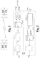
- Fig. 1 shows a Free Space Optics (FSO) system. It simply comprises two FSO apparatus, namely a first FSO transceiver and a second FSO transceiver placed at a certain distance one to each other.
- Each FSO transceiver comprises a Tx side (with a laser transmitter) and an Rx side (with a laser receiver).
- the laser transmitter transmits laser signals through the air, the laser signals being received at the laser receiver of the corresponding FSO transceiver.
- FIG. 2 a first embodiment of the present invention is shown.
- Fig 2 and Fig. 3 show a FSO transceiver very schematically with the purpose of illustrating the main features of the present invention. Details not directly related to the present invention will be not shown.
- the receiving side RX of the embodiment of Fig. 2 comprises an optical interface OI for receiving optical signals ROS transmitted through the air, a laser detector LD for detecting and focusing the laser signal ROS, an electrical interface El for converting the signal into electrical, a transimpedance amplifier TA for transducing a current into a signal voltage, a RX switch which is fed by the output of the transimpedence amplifier TA, a number of output filters FLT1, FLT2 for producing signals at different bit-rates (Bit-Rate 1, Bit-Rate 2).
- the signals output from the filters FLT are sent to demodulators DEMOD (not shown) and will be managed as usual.
- the transmitting side of the embodiment of Fig. 2 comprises a laser transmitter LT which is fed by a signal at a certain bit-rate of a number of bit-rates, the bit-rate by which the laser transmitter is fed being selected by a TX Switch.
- Both the RX and TX switches are driven through a switching algorithm block SAB.
- the switching algorithm mainly operates according to the power level PL of the optical signal that is received and to the information from auto-tracking systems.
- Power level information PL are derived by the transimpedance amplifier TA and fed to the switching algorithm block SAB for performing a power monitoring.
- the switching algorithm block receives further information INFO.
- further information INFO relates to link visibility and meteorological conditions possibly decreasing the power level of the signal at the receiving side.
- the transmission bit-rate is, for instance, Bit-Rate 1. If the detected power level becomes lower for any cause (generally not for mis-alignment problems) or the meteorological conditions become bad, the bit-rate is changed to a lower bit-rate, for instance Bit-Rate 2.
- the same bit-rate switching command SC from the switching algorithm block is sent to the RX Switch and to the TX Switch at the very same time because it is assumed that the transmission medium (air) has mutual characteristics in transmission and in reception. This switch operation results in a transmission at a lower bit-rate and in the receiver that is arranged for receiving at such a lower bit-rate.
- bit-rate will be changed back to Bit-Rate 1. It is thus realized that the present invention could be termed as a "co-lambda back-up technique" as the bit-rate switch is operated at the same wavelength.
- the transmission bit-rate is switched to a lower bit-rate (for instance Bit-Rate 2)
- the output from the transimpedence amplifier TA is sent to the second corresponding filter FLT2 and to common demodulation blocks DEMOD (not shown).
- the laser transmitter LT will receive the signal to be air-transmitted at a lower bit-rate (for instance Bit-Rate 2) from the TX Switch, driven by the switching command SC from the switching algorithm block SAB.
- the above switching command SC is also provided out of the transceiver for selecting the information to be transmitted in case of lower bit-rate.
- some information could not be transmitted. For this reason, it is requested to decide in advance a certain priority of the information to be transmitted. For instance, there will be high priority information to be transmitted also at the lowest bit-rate; medium priority information to be transmitted at an intermediate bit-rate (together with the high priority information); low priority information to be transmitted at the higher bit-rate (together with both the high and medium priority information).
- the traffic will be organized in only two priorities: low priority traffic will be sent only when the first bit-rate is selected.
- Fig. 3 shows a further embodiment of the transceiver TX/RX according to the present invention.
- the main difference is in the transmission side and lies in using an optical switch ORX-Switch and a number of different receiving lines that are optimized for a corresponding bit-rate.
- the receiving side RX of the embodiment shown in Fig. 1 comprises: an optical interface OI, an optical switch ORX-Switch, a number n of laser detectors LD, a number n of electrical interfaces El, a number n of transimpedence amplifiers TA and a number n of filters FLT.
- the output from filters FLT is sent to demodulation blocks (not shown).
- demodulation blocks not shown.
- n is equal to 2 in the example of Fig. 3.
- the transmission side is the same as the one of Fig. 2.
- the switching algorithm block is fed by the same information as in the first embodiment (power level PL of the received signal from any of the transimpedence amplifiers, visibility and meteorological information INFO).
- the main difference is that it will drive the optical switch ORX-Switch by a switching command SC.
- the switching command SC is also provided out of the transceiver for selecting the information to be transmitted in case of lower bit-rate.
- EWT TE RX + EWM where EWM , the early warning margin, could be 3dB, for instance.
- the possible switch criteria could be: "issuing a switching command and perform a bit-rate switch when RL ⁇ EW for a time longer than a certain period". The persistence period of a certain situation before operating the switch is provided in order to avoid useless and frequent changes. An acceptable exemplifying period could be 3 minutes.
- the period is calculated by a counter that is started as soon as it is detected that RL ⁇ EW : the start time is set at present time (the time when it is detected the RL ⁇ EW condition). If present time - start time is equal to x, then switch is true (the bit-rate is switched), otherwise switch is false (the bit-rate is not switched).
Landscapes
- Physics & Mathematics (AREA)
- Electromagnetism (AREA)
- Engineering & Computer Science (AREA)
- Computer Networks & Wireless Communication (AREA)
- Signal Processing (AREA)
- Optical Communication System (AREA)
- Investigating Or Analysing Materials By Optical Means (AREA)
Abstract
Description
- time and space changes of the refractive index n;
- visibility reductions (resulting in a strong attenuation) due to fog, mist, snow and rainfalls.
- Fig. 1 shows a Free Space Optics system;
- Fig. 2 is a schematic representation of a first embodiment of free space optics transceiver according to the present invention; and
- Fig. 3 is a schematic representation of a second embodiment of free space optics transceiver according to the present invention.
Claims (11)
- Method for receiving/trasmitting an optical signal through the air, the method comprising the steps of:the method being characterized by further comprising the steps of:providing a first free space optics apparatus (RX/TX);providing a second free space optics apparatus (RX/TX), the first and second apparatuses being spaced by a certain distance;at the first apparatus, transmitting an optical signal (TOS) through the air at a bit-rate;receiving (ROS), at the second apparatus, said optical signal transmitted through the air by the first apparatus,measuring the power level (PL) of the received signal (ROS); andoperating a bit-rate switch for accomodating the bit-rate in order to change the fading margin in the apparatus.
- Method according to claim 1, characterized in that the step of operating a bit-rate switch is performed by a switching algorithm block (SAB) further respondent to visibility, weather and meterological conditions (INFO).
- Method according to claim 1 or 2, characterized in that the step of operating a switch comprises the step of switching the bit-rate both at the transmission side and the receiving side of the first and second apparatus.
- Method according to any of precending claims, characterized by the further steps of classifying the signals to be transmitted into at least two classes, the number of classes being correspondent to the number of available switchable bit-rates, each class having a corresponding priority; and transmitting lower priorities signals only when the selected transmission bit-rate is the highest one.
- Method according to any preceding claims, characterized in that the step of operating a bit-rate switch is performed, at the receiving side (RX) of the free space optics apparatus (RX/TX), after an amplifying step (TA) and before a demodulation step (DEMOD).
- Method according to any preceding claims, characterized in that the step of operating a bit-rate switch is performed, at the receiving side of the free space optics apparatus, at an optical interface.
- Method according to any of claims 1-6, characterized in that the step of operating a switch is performed when the received power level RL is lower than an early warningthreshold EWT for a certain pre-determined period of time, the early warning EWT being calculated by summing the threshold errors in reception TERX with a predetermined early warning margin EWM.
- A free space optics apparatus for receiving/trasmitting an optical signal through the air from/to a further apparatus being spaced by a certain distance one to each other, the apparatus comprising:characterized in that it further comprises switching means for receiving/transmitting with at least one two different bit-rates, said switching means being responsive at least to the power level (PL) of the received signal.a receiving side (RX) comprising: an optical interface (OI) for receiving optical signals (ROS); at least a transimpedance amplifier (TA); and a number of filters (FLT), with each filter operating at a certain bit-rate;a transmitting side (TX) comprising a laser transmitter (LT);
- Apparatus according to claim 8, characterized in that said switching means are driven by a switching algorithm block further respondent to visibility, weather and meterological conditions.
- Apparatus according to claim 8 or 9, characterized in that said switching means comprise:a switch in the receiving side between the transimpedence amplifier and the filters; anda switch in the transmission side whose output is fed to the laser transmitter.
- Apparatus according to claim 8 or 9, characterized in that said switching means comprise:an optical switch in the receiving side at the input optical interface; anda switch in the transmission side whose output is fed to the laser transmitter.
Priority Applications (4)
| Application Number | Priority Date | Filing Date | Title |
|---|---|---|---|
| AT02291254T ATE453256T1 (en) | 2002-05-22 | 2002-05-22 | METHOD AND DEVICE FOR RECEIVING/TRANSMITTING A FREE-SPACE OPTICAL SIGNAL WITH A CHANGABLE LOSS MARGIN |
| DE60234818T DE60234818D1 (en) | 2002-05-22 | 2002-05-22 | Method and apparatus for receiving / transmitting a free-space optical signal with variable fading margin |
| EP02291254A EP1365526B1 (en) | 2002-05-22 | 2002-05-22 | Method and apparatus for receiving/transmitting an optical signal through the air with a variable fading margin |
| US10/442,044 US20030231887A1 (en) | 2002-05-22 | 2003-05-21 | Method and apparatus for receiving/transmitting an optical signal through the air with a variable fading margin |
Applications Claiming Priority (1)
| Application Number | Priority Date | Filing Date | Title |
|---|---|---|---|
| EP02291254A EP1365526B1 (en) | 2002-05-22 | 2002-05-22 | Method and apparatus for receiving/transmitting an optical signal through the air with a variable fading margin |
Publications (2)
| Publication Number | Publication Date |
|---|---|
| EP1365526A1 true EP1365526A1 (en) | 2003-11-26 |
| EP1365526B1 EP1365526B1 (en) | 2009-12-23 |
Family
ID=29286236
Family Applications (1)
| Application Number | Title | Priority Date | Filing Date |
|---|---|---|---|
| EP02291254A Expired - Lifetime EP1365526B1 (en) | 2002-05-22 | 2002-05-22 | Method and apparatus for receiving/transmitting an optical signal through the air with a variable fading margin |
Country Status (4)
| Country | Link |
|---|---|
| US (1) | US20030231887A1 (en) |
| EP (1) | EP1365526B1 (en) |
| AT (1) | ATE453256T1 (en) |
| DE (1) | DE60234818D1 (en) |
Cited By (3)
| Publication number | Priority date | Publication date | Assignee | Title |
|---|---|---|---|---|
| EP1592153A1 (en) * | 2004-04-27 | 2005-11-02 | Northrop Grumman Corporation | Laser communication system with adaptive data rates |
| CN102104426A (en) * | 2010-12-24 | 2011-06-22 | 安凯 | Adaptive method for determining code rate of diffusion laser communication |
| WO2012041403A1 (en) * | 2010-09-29 | 2012-04-05 | Telefonaktiebolaget L M Ericsson (Publ) | Free space optical communications link node, network and method of transmitting traffic |
Families Citing this family (12)
| Publication number | Priority date | Publication date | Assignee | Title |
|---|---|---|---|---|
| US7178992B2 (en) * | 2003-11-18 | 2007-02-20 | Broadcom Corporation | Apparatus and method of signal detection in an optical transceiver |
| WO2005119942A2 (en) * | 2004-06-01 | 2005-12-15 | The Penn State Research Foundation | Optical wireless communications using ultra short light pulses and pulse shaping |
| JP2008301289A (en) * | 2007-05-31 | 2008-12-11 | Sharp Corp | Optical space transmission receiver circuit, optical space transmission device, optical space transmission system, and electronic device |
| US9496951B2 (en) * | 2013-08-08 | 2016-11-15 | Mark E. Boduch | Method and apparatus for performing path protection for rate-adaptive optics |
| US10038497B2 (en) * | 2013-12-18 | 2018-07-31 | Northrup Grumman Systems Corporation | Optical transceiver with variable data rate and sensitivity control |
| US9236939B2 (en) * | 2014-06-04 | 2016-01-12 | The United States Of America As Represented By The Secretary Of The Navy | Atmospheric transmissometer using a modulated optical source |
| JP6691155B2 (en) * | 2018-02-27 | 2020-04-28 | ファナック株式会社 | Optical communication system and optical transmission module |
| JP2019153872A (en) * | 2018-03-01 | 2019-09-12 | 富士通株式会社 | Transmission device, transmission system, and transmission method |
| US11476949B2 (en) * | 2018-03-29 | 2022-10-18 | Cable Television Laboratories, Inc. | Systems and methods for coherent optics in an access network |
| US10587339B1 (en) | 2018-11-27 | 2020-03-10 | Ciena Corporation | Systems and methods for achieving best effort home route capacity on protection paths during optical restoration |
| TWI763470B (en) * | 2021-05-04 | 2022-05-01 | 瑞昱半導體股份有限公司 | Operation method of network device and control chip of network device |
| CN115396382B (en) * | 2021-05-08 | 2024-08-09 | 瑞昱半导体股份有限公司 | Operation method of network device and control chip of network device |
Citations (2)
| Publication number | Priority date | Publication date | Assignee | Title |
|---|---|---|---|---|
| JPH09261180A (en) * | 1996-01-19 | 1997-10-03 | Toshiba Corp | Space transmission communication device |
| US5760937A (en) * | 1994-08-02 | 1998-06-02 | Fujitsu Limited | Optical demultiplexer |
Family Cites Families (1)
| Publication number | Priority date | Publication date | Assignee | Title |
|---|---|---|---|---|
| FR2655497A1 (en) * | 1989-12-01 | 1991-06-07 | Telecommunications Sa | SYSTEM FOR TRANSMITTING MESSAGES. |
-
2002
- 2002-05-22 EP EP02291254A patent/EP1365526B1/en not_active Expired - Lifetime
- 2002-05-22 AT AT02291254T patent/ATE453256T1/en not_active IP Right Cessation
- 2002-05-22 DE DE60234818T patent/DE60234818D1/en not_active Expired - Lifetime
-
2003
- 2003-05-21 US US10/442,044 patent/US20030231887A1/en not_active Abandoned
Patent Citations (2)
| Publication number | Priority date | Publication date | Assignee | Title |
|---|---|---|---|---|
| US5760937A (en) * | 1994-08-02 | 1998-06-02 | Fujitsu Limited | Optical demultiplexer |
| JPH09261180A (en) * | 1996-01-19 | 1997-10-03 | Toshiba Corp | Space transmission communication device |
Cited By (5)
| Publication number | Priority date | Publication date | Assignee | Title |
|---|---|---|---|---|
| EP1592153A1 (en) * | 2004-04-27 | 2005-11-02 | Northrop Grumman Corporation | Laser communication system with adaptive data rates |
| WO2012041403A1 (en) * | 2010-09-29 | 2012-04-05 | Telefonaktiebolaget L M Ericsson (Publ) | Free space optical communications link node, network and method of transmitting traffic |
| US8989585B2 (en) | 2010-09-29 | 2015-03-24 | Telefonaktiebolaget L M Ericsson (Publ) | Free space optical communications link node, network and method of transmitting traffic |
| CN102104426A (en) * | 2010-12-24 | 2011-06-22 | 安凯 | Adaptive method for determining code rate of diffusion laser communication |
| CN102104426B (en) * | 2010-12-24 | 2013-11-20 | 安凯 | Adaptive method for determining code rate of diffusion laser communication |
Also Published As
| Publication number | Publication date |
|---|---|
| EP1365526B1 (en) | 2009-12-23 |
| US20030231887A1 (en) | 2003-12-18 |
| DE60234818D1 (en) | 2010-02-04 |
| ATE453256T1 (en) | 2010-01-15 |
Similar Documents
| Publication | Publication Date | Title |
|---|---|---|
| EP1365526B1 (en) | Method and apparatus for receiving/transmitting an optical signal through the air with a variable fading margin | |
| US6738584B1 (en) | Method for optical fiber communication, and terminal device and system for use in carrying out the method | |
| US6122084A (en) | High dynamic range free-space optical communication receiver | |
| Kim et al. | Measurement of scintillation for free-space laser communication at 785 nm and 1550 nm | |
| US6940627B2 (en) | Control system for electrochromic devices | |
| EP0637148B1 (en) | Wavelength division multiplex optical transmission system using optical amplification | |
| EP1620961B1 (en) | Method and system for optical performance monitoring | |
| Bloom | The physics of free-space optics | |
| AU721856B2 (en) | Switchable fiber optic device for fiber transmission system and components thereof | |
| US6798567B2 (en) | Method and apparatus for controlling power transients in an optical communication system | |
| Nykolak et al. | 2.5 Gbit/s free space optical link over 4.4 km | |
| JP2004531948A (en) | Optical transmission system with monitoring system | |
| US7113709B2 (en) | Redundant WDM transmission system optical receiver with reduced variable optical attenuators and/or variable dispersion compensation modules | |
| EP0844751A2 (en) | Optical transmitter, terminal-station apparatus having the optical transmitter and optical communication system, monitoring the optical transmitted signal | |
| EP1376904B1 (en) | Optical amplifier and control method therefor | |
| Khajwal et al. | Performance analysis of FSO-SISO and FSO-WDM systems under different atmospheric conditions | |
| EP1411653A2 (en) | Method and device for the control of the power radiated in a free-space optical transmission system | |
| JP5200894B2 (en) | Optical receiver, optical receiving method, and optical transmission device | |
| Winzer et al. | 10-Gb/s upgrade of bidirectional CWDM systems using electronic equalization and FEC | |
| CN1426180A (en) | Light wave length/mode converter | |
| CN102253492B (en) | Laser emission optical system easily coupled with laser-optical fiber combination | |
| US4460241A (en) | Telecommunication system with fiberguide signal filtering | |
| CA2118449A1 (en) | Method and system for indicating an optical transmit amplifier fault | |
| EP1416651B1 (en) | Optical receiver | |
| CN112039598B (en) | Channel power automatic search adjustment method and system based on bit error rate |
Legal Events
| Date | Code | Title | Description |
|---|---|---|---|
| PUAI | Public reference made under article 153(3) epc to a published international application that has entered the european phase |
Free format text: ORIGINAL CODE: 0009012 |
|
| AK | Designated contracting states |
Kind code of ref document: A1 Designated state(s): AT BE CH CY DE DK ES FI FR GB GR IE IT LI LU MC NL PT SE TR |
|
| AX | Request for extension of the european patent |
Extension state: AL LT LV MK RO SI |
|
| 17P | Request for examination filed |
Effective date: 20040526 |
|
| AKX | Designation fees paid |
Designated state(s): AT BE CH CY DE DK ES FI FR GB GR IE IT LI LU MC NL PT SE TR |
|
| RAP1 | Party data changed (applicant data changed or rights of an application transferred) |
Owner name: ALCATEL LUCENT |
|
| 17Q | First examination report despatched |
Effective date: 20080318 |
|
| GRAP | Despatch of communication of intention to grant a patent |
Free format text: ORIGINAL CODE: EPIDOSNIGR1 |
|
| GRAS | Grant fee paid |
Free format text: ORIGINAL CODE: EPIDOSNIGR3 |
|
| GRAA | (expected) grant |
Free format text: ORIGINAL CODE: 0009210 |
|
| AK | Designated contracting states |
Kind code of ref document: B1 Designated state(s): AT BE CH CY DE DK ES FI FR GB GR IE IT LI LU MC NL PT SE TR |
|
| REG | Reference to a national code |
Ref country code: GB Ref legal event code: FG4D |
|
| REG | Reference to a national code |
Ref country code: CH Ref legal event code: EP |
|
| REG | Reference to a national code |
Ref country code: IE Ref legal event code: FG4D |
|
| REF | Corresponds to: |
Ref document number: 60234818 Country of ref document: DE Date of ref document: 20100204 Kind code of ref document: P |
|
| REG | Reference to a national code |
Ref country code: NL Ref legal event code: VDEP Effective date: 20091223 |
|
| PG25 | Lapsed in a contracting state [announced via postgrant information from national office to epo] |
Ref country code: FI Free format text: LAPSE BECAUSE OF FAILURE TO SUBMIT A TRANSLATION OF THE DESCRIPTION OR TO PAY THE FEE WITHIN THE PRESCRIBED TIME-LIMIT Effective date: 20091223 Ref country code: SE Free format text: LAPSE BECAUSE OF FAILURE TO SUBMIT A TRANSLATION OF THE DESCRIPTION OR TO PAY THE FEE WITHIN THE PRESCRIBED TIME-LIMIT Effective date: 20091223 |
|
| PG25 | Lapsed in a contracting state [announced via postgrant information from national office to epo] |
Ref country code: AT Free format text: LAPSE BECAUSE OF FAILURE TO SUBMIT A TRANSLATION OF THE DESCRIPTION OR TO PAY THE FEE WITHIN THE PRESCRIBED TIME-LIMIT Effective date: 20091223 |
|
| PG25 | Lapsed in a contracting state [announced via postgrant information from national office to epo] |
Ref country code: PT Free format text: LAPSE BECAUSE OF FAILURE TO SUBMIT A TRANSLATION OF THE DESCRIPTION OR TO PAY THE FEE WITHIN THE PRESCRIBED TIME-LIMIT Effective date: 20100423 Ref country code: NL Free format text: LAPSE BECAUSE OF FAILURE TO SUBMIT A TRANSLATION OF THE DESCRIPTION OR TO PAY THE FEE WITHIN THE PRESCRIBED TIME-LIMIT Effective date: 20091223 Ref country code: ES Free format text: LAPSE BECAUSE OF FAILURE TO SUBMIT A TRANSLATION OF THE DESCRIPTION OR TO PAY THE FEE WITHIN THE PRESCRIBED TIME-LIMIT Effective date: 20100403 |
|
| PG25 | Lapsed in a contracting state [announced via postgrant information from national office to epo] |
Ref country code: BE Free format text: LAPSE BECAUSE OF FAILURE TO SUBMIT A TRANSLATION OF THE DESCRIPTION OR TO PAY THE FEE WITHIN THE PRESCRIBED TIME-LIMIT Effective date: 20091223 |
|
| PG25 | Lapsed in a contracting state [announced via postgrant information from national office to epo] |
Ref country code: CY Free format text: LAPSE BECAUSE OF FAILURE TO SUBMIT A TRANSLATION OF THE DESCRIPTION OR TO PAY THE FEE WITHIN THE PRESCRIBED TIME-LIMIT Effective date: 20091223 Ref country code: GR Free format text: LAPSE BECAUSE OF FAILURE TO SUBMIT A TRANSLATION OF THE DESCRIPTION OR TO PAY THE FEE WITHIN THE PRESCRIBED TIME-LIMIT Effective date: 20100324 |
|
| PLBE | No opposition filed within time limit |
Free format text: ORIGINAL CODE: 0009261 |
|
| STAA | Information on the status of an ep patent application or granted ep patent |
Free format text: STATUS: NO OPPOSITION FILED WITHIN TIME LIMIT |
|
| 26N | No opposition filed |
Effective date: 20100924 |
|
| PG25 | Lapsed in a contracting state [announced via postgrant information from national office to epo] |
Ref country code: MC Free format text: LAPSE BECAUSE OF NON-PAYMENT OF DUE FEES Effective date: 20100531 |
|
| REG | Reference to a national code |
Ref country code: CH Ref legal event code: PL |
|
| PG25 | Lapsed in a contracting state [announced via postgrant information from national office to epo] |
Ref country code: DK Free format text: LAPSE BECAUSE OF FAILURE TO SUBMIT A TRANSLATION OF THE DESCRIPTION OR TO PAY THE FEE WITHIN THE PRESCRIBED TIME-LIMIT Effective date: 20091223 |
|
| PG25 | Lapsed in a contracting state [announced via postgrant information from national office to epo] |
Ref country code: CH Free format text: LAPSE BECAUSE OF NON-PAYMENT OF DUE FEES Effective date: 20100531 Ref country code: LI Free format text: LAPSE BECAUSE OF NON-PAYMENT OF DUE FEES Effective date: 20100531 |
|
| PG25 | Lapsed in a contracting state [announced via postgrant information from national office to epo] |
Ref country code: IT Free format text: LAPSE BECAUSE OF FAILURE TO SUBMIT A TRANSLATION OF THE DESCRIPTION OR TO PAY THE FEE WITHIN THE PRESCRIBED TIME-LIMIT Effective date: 20091223 |
|
| PG25 | Lapsed in a contracting state [announced via postgrant information from national office to epo] |
Ref country code: IE Free format text: LAPSE BECAUSE OF NON-PAYMENT OF DUE FEES Effective date: 20100522 |
|
| PG25 | Lapsed in a contracting state [announced via postgrant information from national office to epo] |
Ref country code: LU Free format text: LAPSE BECAUSE OF NON-PAYMENT OF DUE FEES Effective date: 20100522 |
|
| PG25 | Lapsed in a contracting state [announced via postgrant information from national office to epo] |
Ref country code: TR Free format text: LAPSE BECAUSE OF FAILURE TO SUBMIT A TRANSLATION OF THE DESCRIPTION OR TO PAY THE FEE WITHIN THE PRESCRIBED TIME-LIMIT Effective date: 20091223 |
|
| REG | Reference to a national code |
Ref country code: FR Ref legal event code: GC Effective date: 20131018 |
|
| REG | Reference to a national code |
Ref country code: FR Ref legal event code: RG Effective date: 20141016 |
|
| REG | Reference to a national code |
Ref country code: FR Ref legal event code: PLFP Year of fee payment: 14 |
|
| REG | Reference to a national code |
Ref country code: FR Ref legal event code: CA Effective date: 20150521 |
|
| REG | Reference to a national code |
Ref country code: FR Ref legal event code: CA Effective date: 20150521 |
|
| PGFP | Annual fee paid to national office [announced via postgrant information from national office to epo] |
Ref country code: GB Payment date: 20150521 Year of fee payment: 14 Ref country code: DE Payment date: 20150521 Year of fee payment: 14 |
|
| PGFP | Annual fee paid to national office [announced via postgrant information from national office to epo] |
Ref country code: FR Payment date: 20150521 Year of fee payment: 14 |
|
| REG | Reference to a national code |
Ref country code: DE Ref legal event code: R119 Ref document number: 60234818 Country of ref document: DE |
|
| GBPC | Gb: european patent ceased through non-payment of renewal fee |
Effective date: 20160522 |
|
| REG | Reference to a national code |
Ref country code: FR Ref legal event code: ST Effective date: 20170131 |
|
| PG25 | Lapsed in a contracting state [announced via postgrant information from national office to epo] |
Ref country code: FR Free format text: LAPSE BECAUSE OF NON-PAYMENT OF DUE FEES Effective date: 20160531 Ref country code: DE Free format text: LAPSE BECAUSE OF NON-PAYMENT OF DUE FEES Effective date: 20161201 |
|
| PG25 | Lapsed in a contracting state [announced via postgrant information from national office to epo] |
Ref country code: GB Free format text: LAPSE BECAUSE OF NON-PAYMENT OF DUE FEES Effective date: 20160522 |