EP1365301A2 - Method and system for maneuvering a movable object - Google Patents
Method and system for maneuvering a movable object Download PDFInfo
- Publication number
- EP1365301A2 EP1365301A2 EP03011400A EP03011400A EP1365301A2 EP 1365301 A2 EP1365301 A2 EP 1365301A2 EP 03011400 A EP03011400 A EP 03011400A EP 03011400 A EP03011400 A EP 03011400A EP 1365301 A2 EP1365301 A2 EP 1365301A2
- Authority
- EP
- European Patent Office
- Prior art keywords
- movable object
- point
- weights
- thrust
- ship
- Prior art date
- Legal status (The legal status is an assumption and is not a legal conclusion. Google has not performed a legal analysis and makes no representation as to the accuracy of the status listed.)
- Granted
Links
Images


Classifications
-
- G—PHYSICS
- G05—CONTROLLING; REGULATING
- G05D—SYSTEMS FOR CONTROLLING OR REGULATING NON-ELECTRIC VARIABLES
- G05D1/00—Control of position, course or altitude of land, water, air, or space vehicles, e.g. automatic pilot
- G05D1/02—Control of position or course in two dimensions
- G05D1/0206—Control of position or course in two dimensions specially adapted to water vehicles
Definitions
- the present invention relates to a method and system for maneuvering a movable object and more particularly to a method and system for automatically track-keeping a movable object so as to move along a planned route.
- a marine track-keeping method For instance, Japanese Patent Publication Kokai Gazette No. 2001-287697 discloses an track-keeping method. This track-keeping method is carried out in the following way: a destination point is set at a position a specified distance away from the present location on the planned route; course and heading deviations are calculated from the destination point; and thrust that needs to be output from a plurality of propellers (hereinafter, referred to as "actuators") is calculated from the calculated deviations.
- the route is a continuous planned ship course constituted by a plurality of line segments and a circular arc having a certain radius.
- a position control method for a movable object is disclosed in the Forty-fourth Automatic Control Association Lecture Meeting Gazette No. 01-253, pp 116 to 119.
- This position control method for a movable object teaches position control of a hover craft by the non-linear optimizing feed-back control, but does not discuss maneuver in consideration of constraints to a planned route.
- Another position control method for the same movable object is disclosed in "Measurement and Control" Vol. 36, No. 11 (November, 1997), pp776 to 783.
- This movable object position control method employs a maneuver technique for avoiding obstacles according to which penalty functions associated with the position of a movable object are included in a performance index.
- the present invention is directed to overcoming the foregoing drawbacks and a primary object of the invention is therefore to provide a movable object maneuver method and system capable of automatically track-keepig a movable object so as to track an optimum route which passes a desired destination point, while minimizing power in compliance with given constraints.
- the object can be accomplished by a method and system for maneuvering a movable object according to the invention, wherein a destination point is set, wherein a thrust value is calculated in real time which minimizes or maximizes a performance index associated with one or more state variables and thrust required for a movable object to reach the destination point and which takes into account non-linear conditions inherent to the movable object, and wherein the movable object is moved based on the calculated thrust value.
- This obviates not to need for calculating a route beforehand like the prior art and controls the movable object through actual position control while calculating an optimum route directed to the destination point in real time, so that even if disturbances affect the movable object, it can automatically track the optimum route with the minimum power that meets given conditions.
- a method and system for maneuvering a movable object wherein a destination point is set, a thrust value is calculated in real time which minimizes or maximizes a performance index associated with a thrust required for a movable object to reach the destination point, and the movable object is moved based on the calculated thrust value; and wherein one or more transit points are set on a planned route for the movable object and on or more set transit points are sequentially set as the destination point.
- the thrust value may be calculated in real time which minimizes or maximizes the performance index over a specified period of time from the present time to a future time.
- the performance index may include weights for the state variables, the thrust and each term, the weights may be set as constraints which limit the values of the state variables and the thrust, and the thrust value restricted by the set constraints may be calculated. Thanks to this arrangement, the desired response and performance of the movable object can be obtained by adjusting the weights with the minimum thrust.
- the planned route may include only two transit points which are a starting point and a terminal point, and the two transit points may be set to the same point. This makes it possible to carry out route tracking and way point keeping with the same algorithm, which leads to simplification of the control method.
- a guide point may be set which consists of a virtual point and moves on the planned route, preceding the movable object, and when the guide point has reached a transit point which is the present destination point, the destination point may be switched to the next transit point.
- the performance index may include weights for the state variables, the thrust and each term, the weights may be set for each zone of the planned route as constraints which limit the values of the state variables and the thrust, each zone being defined by the transit points, and the thrust value restricted by the constraints corresponding to each transit point may be calculated.
- the weights may be set as constants.
- the weights may be set as function of positions.
- the weights may be set as functions of the position and attitude of the movable object.
- the weights may be set as functions of deviation from the state variables at the destination point.
- the weights may be set as function of speeds.
- the maximum speed of the movable object for instance, can be set by properly setting the weights.
- the weights may be set as function of times.
- the movable object can be automatically stopped or started, for instance, by setting the weight for the speed of the movable object so as to properly vary with respect to time.
- the weights may be set as functions of an event signal.
- the speed of the movable object can be varied in accordance with an event signal, for instance, by setting the weight for the speed of the movable object so as to properly vary relative to an event signal, and it becomes possible to stop or start the movable object upon receipt of an event signal.
- the weights may be set as functions of data on obstacles.
- the movable object can be allowed to avoid obstacles, by setting the weight for deviation from the route so as to properly vary in accordance with data on the obstacles.
- the destination point may be set by switching it from the present location to any of other points than the present location.
- the movable object can be stopped or started, for instance, by causing an event through pressing of an operation button.
- the performance index may include the state variables and the thrust as variables and the state of the movable object may be estimated, using a non-linear or linear state observer. This makes it possible to properly carry out the optimizing control, by estimating the state variables which is directly undetectable.
- Necessary items including the target point and the performance index may be set using a human-machine interface. This enables easy setting of necessary items.
- the movable object may be a ship.
- the movable object may be an underwater craft.
- the movable object may be an aircraft.
- Figure 1 is a block diagram showing a structure of a control system of a movable object maneuver system according to a first embodiment of the invention.
- Figure 2 is a block diagram showing a structure of the control unit shown in Figure 1.
- Figure 3 diagrammatically shows a layout of individual actuators.
- a ship maneuver system 1 exemplifies the movable object maneuver system in the present embodiment.
- the movable object is a ship 5.
- the ship maneuver system 1 has a route data input device 2, a control unit 3, actuators 4, a position detecting device 6, and an heading angle detecting device 7.
- the position detecting device 6 is constituted, for instance, by a GPS (Global Positioning System) and measures the position of the ship 5 to output as positional data.
- the heading angle detecting device 7 is constituted, for instance, by a gyro compass and measures the heading of the ship 5 to output as data.
- the route data input device 2 is constituted by an HMI (Human-machine interface) having a display connected to a computer, a mouse, a key board and the like.
- the route data input device 2 functions to input, for setting, route data to the control unit 3, the route data including a planned route (planned ship course: hereinafter referred to as "route”) and the degrees of constraints.
- the control unit 3 is constituted by a computer and performs non-linear optimizing feed-back control on the ship 5, based on the route data input from the route data input device, position data input from the position detecting device 6 and heading angle data input from the heading angle detecting device 7. More concretely, the control unit 3 outputs operation commands for the optimizing feed-back control.
- the actuators 4 produce thrust according to the operation commands output from the control unit 3 to move (maneuver) the ship 5.
- the actuators 4 are composed of, as shown in Figure 3, individual actuators respectively arranged in the ship 5, that is, one thruster 21, two propellers 22, 23 and two rudders 24, 25. With these actuators, the ship 5 can be moved in a desired two-dimensional direction and arbitrarily turned.
- the control unit 3 includes a route optimizing operation unit 8, a thrust allocation unit 9 and an observer 10, which are realized by specified software.
- the route optimizing operation unit 8 performs route optimizing operation to output thrust commands, using an algorithm for minimizing a performance index (described later).
- the thrust allocation unit 9 optimally allocates the thrust commands output from the route optimizing operation unit 8 to the individual actuators 21 to 25 shown in Figure 3 and outputs them as operation commands.
- the observer 10 inputs the state variables of the performance index to be used for the route optimizing operation to the route optimizing operation unit 8.
- the basic configuration of the observer 10 is known and therefore will be briefly described herein.
- the operation commands output from the thrust allocation unit 9 are input to mathematical models of the ship 5 and the actuators 4 as manipulated variables.
- the output from the mathematical models are compared with the position data and heading angle data on the ship 5 (i.e., the outputs of the position detecting device 6 and the heading angle detecting device 7) and the differences are input to the mathematical models.
- state variables (x, y, ⁇ , u, v, r) are taken from proper locations of the mathematical models to input to the route optimizing operation unit 8 as estimated values for the state variables of the ship 5.
- the thrust commands output from the route optimizing operation unit 8 may be arranged as thrust commands directed to the actuators.
- Figure 4 diagrammatically shows a method of setting a route.
- Figure 5 is a graph showing the definitions of state variables.
- Figures 6(a),(b) are diagrammatical views showing an example of setting of a weight for an performance index, wherein Figure 6(a) shows the condition of a route whereas Figure 6(b) shows changes in the weight.
- Figure 7 is a table exemplifying the definitions of constraint levels.
- a plurality of transit points (hereinafter referred to as "way points") WP are assumed to exist on a virtual plane as shown in Figure 4 and straight lines connecting the plural way points WP are defined as a route 101. While sequentially switching the plural way points WP on the route 101 to set as a destination point, the optimizing control is performed.
- the route 101 is defined in the global coordinate system, while a local coordinate system x i -y i is defined for every section 102 between two way points on the route 101 (hereinafter simply referred to as "section").
- this local coordinate system x i -y i can be arbitrarily defined, it is defined herein such that the way point WP i is set as an origin point and the x i axis coincides with a section 102 i which extends forward from the way point WP i .
- control is performed with the local coordinate system corresponding to the present way point WP.
- the position and heading angle of the ship 5 is converted to the local coordinate system corresponding to each way point WP.
- the terminal condition of the performance index is regarded as the state of the next way point WP i+1 on the local coordinate system x i -y i corresponding to the present way point WP i and weights for the performance index are determined for every section 102.
- the coordinate system is switched to the local coordinate system X i+1 -y i+1 corresponding to the way point WP i+1 and the weights for the performance index are switched to those for the section 102 i+1 .
- the present invention is designed such that a guide point GP which moves on the route 101 in accordance with the movement of the ship 5 is set and the destination point is changed whenever the guide point GP has reached a way point WP.
- the guide point GP is positioned a distance D ahead of a projection point P mxi on the axis x i of the local coordinate system for the center of the ship 5 and moves at the same speed as the moving speed of the projection point P mxi .
- the distance D is a function of, for instance, sailing speed, lateral deviation from the route 101, heading angle deviation, the distance to a way point WP serving as the destination point, the values of weights for a preset performance index and the like, but not limited to these factors.
- the optimum value which minimizes the performance index such as described by the equation (2) where t is a given time and t+T is a future time, is calculated using the state equation for the ship such as the equation (1) (i.e., optimization over a time period T from a time t to a future time t + T), and only the initial value u(t) of the optimizing control is given as an actual manipulated variables.
- x (t) f (x(t),u(t),p(t)) where x(t) is a vector of state variables, u(t) is a vector of manipulated variables, and p(t) is a given time variant parameter.
- x ref is a target state (the position and state of the ship at a WP serving as the destination point)
- S is a weight for a terminal state
- Q is a weight for a state variables
- R is a weight for manipulated variables.
- this performance index appropriate functions are selected for ⁇ and L, appropriate values are set for S, Q and R, and u(t) which minimizes the performance index is obtained. Then, an operation command value for the actuators is calculated, using u(t) as a command value for thrust for the ship. This arithmetic operation is performed in real time.
- the first term is for evaluating the state at a future time which comes a specified time after the present time
- the second term is for evaluating the state variables and manipulated variables (thrust) over a specified period of time from the present time to the future time.
- the weights S, Q and R of the performance index are variant so that their values can be arbitrary changed depending on data on the KEEP OUT zone, the distance to the way point WP serving as the destination point and user's instructions.
- equation (3) is defined as a preferable concrete example of the performance index of the equation (2).
- equations (10) to (12) are the approximate expressions of the dynamic characteristics of the thrust allocation unit 9 and the actuators 4 shown in Figure 2. Although each dynamic characteristic is approximated by a primary delay system herein, the approximation is not limited to this but an arbitrary equation may be employed.
- x the x coordinate of the center of the ship
- y the y coordinate of the center of the ship
- ⁇ the heading angle of the ship
- u the speed of the ship in a fore-off direction (longitudinal direction);
- v the speed of the ship in a lateral direction (widthwise direction);
- r the angular speed of the ship
- X a thrust working on the ship in its fore-off direction
- Y a thrust working on the ship in its lateral direction
- N a moment about the center of the ship
- Xr a command value indicative of a thrust to be exerted in the fore-off direction of the ship
- Yr a command value indicative of a thrust to be exerted in the lateral direction of the ship
- Nr a command value indicative of a moment about the center of the ship
- M the mass of the ship
- mx an added mass in the fore-off direction
- my an added mass in the lateral direction
- Izz a
- the weights S fi , q i , r i of the performance index of the equation (3) are variant, so that their values are changed according to data on KEEP OUT zones, the distance to a way point WP serving as the destination point, the degree of a route constraint and others.
- a weight q 3 for y is set taking account of the region 201 as shown in Figure 6(b). More specifically, with respect to the direction of the y i axis in a local coordinate system, the weight q 3 is set to take a constant value V0 within the area where the region 201 does not exist and to rapidly increase in the area where the region 201 exists.
- a zone A1 where the value of the weight is constant and a zone A2 where the value of the weight increases are set based on the route 101, taking account of the condition of the deviation (i.e., the difference between the state variables at the destination point and the state variables at the present location). Since the weight does not take discrete values, the weight is set to have continuous values.
- the zone A1 where the weight has a constant value is changed according to, for instance, the distance to the way point WP serving as the destination point. The degree of a constraint to the route 101 is adjusted, depending on the length of the zone A1 where the weight has a constant value.
- the degree of this constraint can be set so as to vary continuously, but, in the present embodiment, it is divided into, for example, five levels, "Non”, “Loose”, “Middle”, “Tight”, “Strict", in proportion to the length of the zone A1 where the weight has a constant value, as shown in Figure 7.
- the lower limit value V0 of the weight is changed depending on the distance to the way point WP serving as the destination point or the like.
- the zone A2 where the weight increases can be set for both the starboard side and port side of the ship.
- the degree of the route constraint may be set by changing the weight for other state variables such as the heading angle or speed of the ship, similarly to the case where the weight for the position of the ship is changed.
- Figures 8(a),8(b) are views each showing a controlled state of a ship, wherein Figure 8(a) shows a present embodiment whereas Figure 8(b) shows a prior art example.
- the route data input device 2 sends way points WP, the state variables at the destination point, the leading distance D of the guide point and weights (including the degree of a route constraint) for each section 102 and the like to be input to the control unit 3 for setting.
- the route optimizing operation unit 8 calculates, in real time, a two-directional force (thrust commands Xr, Yr) and a moment (thrust command Nr) which minimize the performance index of the equation (3).
- These calculated thrust commands are allocated to the individual actuators 21 to 25 of the actuators 4 by the thrust allocation unit 9, and the allocated thrust commands are output to the actuators 4 as operation commands.
- the individual actuators 21 to 25 output thrusts based on the operation commands.
- the ship 5 moves.
- the position detecting device 6 and the heading angle detecting device 7 measure the position and heading angle of the ship 5 respectively and the observer 10 inputs the present state variables based on the measured position, the measured heading angle and the operation commands output from the thrust allocation unit 9 to the route optimizing operation unit 8.
- the ship 5 is controlled so as to track an optimum route from the present location to the way point WP serving as the destination point, as shown in Figure 8(a).
- the route optimizing operation unit 8 switches the destination point to the next way point WP and controls the ship 5 similarly.
- the degree of the route (101) constraint imposed on the ship 5 varies according to the weights for the performance index set for every section 102.
- the ship is controlled so as to null the deviation from the target value as shown in Figure 8(b) and therefore the ship sails, outputting necessary power to null the deviation even if disturbances such as winds and currents affect on the ship, so that a great amount of power is consumed.
- the present embodiment is designed such that the ship is controlled while calculating an optimum route to the destination point in real time, so that even if disturbances occur, the ship can track the optimum route with power minimized in compliance with given conditions, provided that the ship sails within a preset constraint degree range.
- Figure 9 shows a simulation result associated with Example 1.
- the abscissa represents the x coordinate whereas the ordinate represents the y coordinate.
- Thick lines represent the target position and target heading angle of the ship 5 at the way points WP0 and WP1, respectively. While the ship 5 moves from the way point WP0 to the way point WP1 (with its position changing), the heading angle of the ship 5 changes from the heading angle at the way point WP0 to the heading angle at the way point WP1.
- the optimizing control is performed by use of a performance index in which each term is weighed like the equations (1) and (3), if the weights are increased, the performance index increases with the increase in the weights, so that the state of the ship does not become close to the zone where the weights increase.
- the weights for the position and heading angle of the ship 5 are set to increase, but the constraint level for them is set to "Loose" (small: see Figure 7) and therefore the degree of the route constraint due to the weights is small. Therefore, the ship 5 moves from the way point WP to the way point WP1, tracking a course that is relatively distant from the route 101.
- Figure 10 shows a simulation result associated with Example 2.
- the abscissa represents the x coordinate whereas the ordinate represents the y coordinate.
- the constraint level with respect to the position of the ship is set to "Strict” (extremely great: see Figure 7)
- the constraint level with respect to the heading angle of the ship is set to "Loose” (small). Accordingly, the ship 5 substantially sails on the route 101, moving from the way point WP0 to the way point WP1.
- Figure 11 shows a simulation result associated with Example 3.
- the abscissa represents the x coordinate whereas the ordinate represents the y coordinate.
- the level of the constraint to the position of the ship is set to "Middle” (middle: see Figure 7) and the level of the constraint to the heading angle of the ship is set to "Loose" (small). Therefore, the ship 5 tracks a course that is slightly distant from the route 101, moving from the way point WP0 to the way point WP1.
- Figure 12 shows a simulation result associated with Example 4.
- the abscissa represents the x coordinate whereas the ordinate represents the y coordinate.
- the levels of the constraints to the position of the ship and to the heading angle of the ship are both set to change from "Loose" (small) to "Strict” (extremely great). Therefore, the ship 5 is substantially located on the route 101 and its heading angle becomes close to the target heading angle at the way point WP1 when it sails on the way from the way point WP0 to the way point WP1. When sailing from there to the way point WP1, the ship substantially tracks the route 101 with its heading angle slightly changing.
- the ship 5 can be moved between way points WP, taking a desired course and attitude, by appropriately setting weights for the position and heading angle of the ship 5. These weights can be readily set by the operator's sensuous judgement.
- Figure 13 diagrammatically illustrates a shipping route employed in the simulation of Example 5.
- Figure 14 illustrates a simulation result according to Example 5.
- the abscissa represents the x coordinate whereas the ordinate represents the y coordinate.
- a jetty 302 having an opening 302a at its center is located in the port and a pier 301 is located at the right far side of the opening 302a.
- a first way point WP0 is set at the approximate center of the opening 302a of the jetty 302, and a second way point WP 1 is set on the left hand of the pier 301 in front of the opening 302a.
- Third to fifth way points WP2 to WP4 are set to depart from the second way point WP 1, surrounding the leading end of the pier 301.
- a sixth way point WP5 is set alongside the pear 301 at a position straight ahead of the fifth way point WP4.
- the heading angle of the ship 5 at the first to third way points WP0 to WP2 is the same as the heading angle which the ship takes when coming into the port and the heading angle of the ship 5 at the fourth and sixth way points WP3 to WP5 is opposite to the heading angle at the time of entry into the port.
- the level of the constraint to the position of the ship 5 is set to "Loose” (small) for all the sections 102.
- the level of the constraint to the heading angle of the ship 5 is set to "Loose” for the section 102 between the fifth way point WP4 and the sixth way point WP5 and to "Non” (nothing: See Figure 7) for other sections 102.
- Figure 15 shows a simulation result associated with Example 6.
- the abscissa represents the x coordinate whereas the ordinate represents the y coordinate.
- the levels of the constraints to the position of the ship 5 and to the heading angle of the ship 5 are both set to "Loose" (small) for all the sections 102.
- the ship 5 made a turn with a large radius while sailing from the third way point WP2 to the fourth way point WP3 so that the bow of the ship excessively came close to the jetty 302, causing a dangerous situation.
- Figure 16 shows a simulation result associated with Example 7.
- the abscissa represents the x coordinate whereas the ordinate represents the y coordinate.
- the level of the constraint to the position of the ship 5 was set to "Strict" (extremely great) for all the sections 102.
- the level of the constraint to the heading angle of the ship 5 was set to "Loose” (small) for the section 102 between the first way point WP0 and the second way point WP1; set to change from “Loose” (small) to “Strict” (extremely great) for each section 102 between the second way point WP1 and the fifth way point WP4; and set to "Strict” (extremely great) for each section 102 between the fifth way point WP4 and the six way point WPS.
- the ship 5 substantially sailed on the route 101 between the third way point WP2 and the fourth way point WP3 and turned in the vicinity of the fourth way point 3, so that the risk that the bow came close to the jetty 302 could be avoided and a good result was obtained.
- control of the present embodiment enables adequate automatic mooring of the ship 5 by properly setting a route and properly selecting weights for the position and heading angle of the ship 5.
- a second embodiment of the present invention exemplifies the preferred HMI.
- Figures 17(a) to 17(d) are diagrammatic views each illustrating an HMI route setting screen (an image of screen) according to the present embodiment, wherein Figure 17(a) shows setting of a KEEP OUT zone, Figure 17(b) shows a state in which a route has been partly set, and Figure 17(c) shows a state in which setting of a route has been completed.
- the HMI of this embodiment is constituted by, as previously discussed in the first embodiment, a display unit such as a display connected to the control unit 3 (computer: see Figure 1) and an input device such as a mouse and a key board.
- a display unit such as a display connected to the control unit 3 (computer: see Figure 1)
- an input device such as a mouse and a key board.
- a route setting screen is first displayed on the display unit and then, KEEP OUT zones such as the obstacles 301, 302 are manually set, operating the mouse or the like on the setting screen. It is also possible to automatically set the KEEP OUT zones by inputting GPS data or MAP data to the control unit 3.
- the way points WP0 to WP5 are specified by operating the mouse, as shown in Figures 17(b) and 17(c). Then, the position data on the way points WP0 to WP5 is transferred to and stored in the control unit 3 (setting). The way points WP0 to WP5 are sequentially connected by straight lines which are, in turn, displayed on the screen. In this way, a route is set.
- Figure 18 diagrammatically shows setting of the degree of the route constraint.
- a screen 402 is displayed for setting the degree of the route constraint for the section 102.
- slide bars ((403a, 403b), (404a, 404b)) for use in setting the degree of a constraint to the position of the ship are displayed beside way points WP i , WP i+1 , respectively, on the starting point side and terminal point side of the section 102.
- Rotating bars ((405, 406), (407a, 407b), (408a, 408b)) for use in setting the degree of a constraint to the heading angle of the ship are displayed on the way points WP i, WP i+1 , respectively, on the starting point side and terminal point side of the section 102. Further, a slide bar 411 used for setting a speed limit (the maximum speed value) for the ship is displayed at an appropriate position on the screen. After the slide bars 403a, 403b for the starting point side and the terminal point side have been positioned at their respective desired positions, a straight line 403c connecting the positions of the slide bars 403a and 403b is displayed.
- the positions of the slide bars 403a, 403b and the straight line 403c indicate the positions at each of which the weight starts to increase in relation to a deviation from the route 101 to port (a deviation in the y-direction). In this way, the degree of the constraint to the position of the ship with respect to the port side of the ship, i.e., the y direction is set.
- a straight line 404c connecting the positions of the slide bars 404a, 404b is displayed.
- the positions of the slide bars 404a, 404b and the straight line 404c indicate the positions at each of which the weight starts to increase in relation to a deviation from the route 101 to starboard (a deviation in the y-direction). In this way, the degree of the constraint to the position of the ship with respect to the starboard side of the ship, i.e., the y direction is set.
- the rotation angles of the rotating bars 405, 406 on the starting point side and the terminal point side indicate target heading angle values at the way points on the starting point side and on the terminal point side, respectively. By positioning the rotating bars 405, 406 at their respective desired rotation angles, target heading angle values at the way points on the starting point side and on the terminal point side can be set.
- the rotation angles of the rotating bar 407a on the starting point side and the rotating bar 407b on the terminal point side indicate the heading angles at each of which the weight for the port deviation of the heading angle from the target angle at the way point on the starting point side (the terminal point side) increases.
- the degrees of the constraint to the port deviation of the heading angle of the ship at the way points on the starting point side and on the terminal point side are set.
- the rotation angles of the rotating bar 408a on the starting point side and the rotating bar 408b on the terminal point side indicate the heading angles at each of which the weight for the starboard deviation of the heading angle from the target angle at the way point on the starting point side (the terminal point side) increases.
- the degrees of the constraint to the starboard deviation of the heading angle of the ship at the way points on the starting point side and on the terminal point side are set.
- the degree of the constraint to the heading angle of the ship can be set so as to change as described later by a specified operation, when the ship is sailing from the starting point side to the terminal point side in an arbitrary section.
- the position of the slide bar 411 indicates the speed at which the weight for the speed of the ship starts to increase. Therefore, the maximum value of the speed of the ship can be set by positioning the slide bar 411 at a desired position.
- Figures 19(a) to 19(g) are diagrammatical views showing examples of setting of weights for a position and for an heading angle, wherein Figures 19(a) to 19(c) show examples of setting of a weight for a position, Figure 19(d) shows an example of setting of the lengths of constant weight zones as functions of a distance to a way point serving as the destination point, and Figures 19(e) to 19(g) show examples of setting of a weight for an heading angle.
- weights for the position with respective to the y direction on the above-described starting point side and terminal point side are set as shown in Figures 19(b), 19(c).
- the lengths Wrs, Wls, Wre, Wle of the constant weight zones on the starting point side and terminal point side correspond to the positions of the slide bars 404a, 403a, 404b, 403b, respectively, shown in Figure 18.
- the lengths Wr, Wl of the constant weight zones on the starboard side and the port side are set so as to vary relative to the distance (i.e., the position with respect to the x direction) to the way point WP i+1 serving as the destination point as shown in Figure 19(d).
- a weight for the position with respect to the x direction can be set as shown in Figure 19(a).
- the weight for the position with respect to the x direction may be a constant value. Where the weight is varied, it is set, for example, as a function of the degree of the constraint to the position with respect to the y direction on the starboard side or port side.
- weights for heading angles on the starting point side and terminal point side are set as shown in Figures 19(e) and 19(f) respectively.
- the lengths Rrs, Rls, Rre, Rle of the weight constant zones on the starting point side and terminal point side correspond to the difference between the heading angles of the rotating bars 408a, 407a, 408b, 407b and their respective target values.
- the lengths Rr, Rl of the constant weight zones where the weight is constant when the ship turns to starboard or port are set to vary relative to the distance (i.e., the position with respect to the x direction) to the way point WP i+1 serving as the destination point, as shown in Figure 19(g).
- Figure 20 shows a method of drawing a curve indicative of changes in a weight for an arbitrary state variables. As shown in Figure 20, this curve is prepared in such a way that a plurality of points each of which indicates a weight value are first plotted and then, these points are connected with an approximate curve.
- Figures 21(a) to 21(p) show examples of the curve prepared through such a process, each of which is indicative of changes in a weight relative to a state variables.
- the route 101 shown in Figure 4 associated with the first embodiment has only two way points, that is, a starting point and a terminal point, and these two way points are set to the same point.
- the ship 5 is controlled so as to be kept at a fixed point.
- this control can be performed with the same algorithm (procedure) as in the case where the ship sails along the route 101, so that the control unit can be simplified.
- the guide point GP of the first embodiment shown in Figure 4 is set as the destination point.
- the local coordinate system and the degree of the route constraint are updated in real time. This arrangement obviates the need for setting way points.
- Figures 22(a),22(b) are views showing the operation and structure of a ship maneuver system according to a fifth embodiment of the invention, wherein Figure 22(a) shows an action for avoiding an obstacle, whereas Figure 22(b) shows changes in a weight for a position with respect to the y direction.
- the ship maneuver system 1 includes an obstacle detector 1.
- the obstacle detector is composed of a radar, an ultrasonic sonar or the like.
- reference numeral 502 designates an obstacle detectable range for the obstacle detector. If the obstacle detector detects an obstacle 501 near the ship 5, the control unit 3 (see Figure 1) sets a weight for the position with respect to the y direction such that it increases, as shown in Figure 22(b), short of the region where the obstacle 501 exists. Specifically, the weight for the position with respect to the y direction is updated in real time based on data on an obstacle. With this arrangement, the ship 5 moves so as to avoid the obstacle 501 as shown in Figure 22(a). As a result, the ship 5 automatically avoids the obstacle 501 near the route 101 and sails safely.
- the weights of the performance index are set as a function of time. For example, if the weight for the speed of the ship is set to change after an elapse of a certain time, the ship will change its speed after an elapse of the certain time. Accordingly, the ship can be automatically stopped or started by properly setting the weight.
- a seventh embodiment of the invention if an event is detected, the speed of the ship will be changed.
- the weights of the performance index are set as a function of an event signal.
- the control unit 3 is designed such that if an operation button has been pressed, the sensor detects it to issue a specified signal (event signal). After the specified signal has been input to the route optimizing operation unit 8, the weight for the speed of the ship is set to vary. With this arrangement, the speed of the ship is changed by pressing the operation button so that the ship can be started or stopped.
- the destination point is switched between other points (e.g., the present destination point (the next way point WP)) than the present location and the present location.
- the operation button is pressed while the ship is sailing, the ship will stop and if the operation button is pressed while the ship is stopped, the ship will start to move.
- the ship goes past the destination point after switching owing to the dynamic characteristics of the ship so that control is performed so as to make the ship return.
- the timing of stopping delays to that extent. It is therefore preferable to take the following measure: the position at which the ship will stop if a specified thrust is exerted, at the present time, in a direction opposite to the heading direction of the ship is predicted, taking account of the dynamic characteristics of the ship and the destination point is switched to the predicted position.
- the ship can be brought to a stop in a shorter time. In this case, the ship can be started by switching the destination point to any of points other than the above predicted point.
- An eighth embodiment of the invention is associated with maneuver of movable objects other than ships.
- the optimizing control with the performance index of the equation (3) is applicable not only to ships but also to other general movable objects.
- the equations (3) to (12) can be applied without change, especially to cases where a movable object moves within a two-dimensional space under the force or moment of resistance, friction and the like.
- Example 8 is associated with an application of the present invention to maneuver of an aircraft.
- Figure 23 is a block diagram showing a structure of the control system of an aircraft maneuver system according to the present example.
- Figure 24 shows an aircraft model and the definitions of state variables according to the present example. It should be noted that the reference numerals common to Figures 1 and 23 represent the same or equivalent parts.
- an object to be controlled by an aircraft maneuver system 601 of the present example is an aircraft 602, and the aircraft maneuver system 601 has an Euler angle detecting device 603 in place of the heading angle detecting device 7 provided for the ship maneuver system 1 shown in Figure 1. Except the above points, the aircraft maneuver system 601 is similar to the ship maneuver system 1.
- the Euler angle detecting device 603 is composed of, for example, a directional gyro and measures the Euler angles of the aircraft to output as Euler angle data.
- the state variables of Example 8 include state variables with respect to the z-axis and Euler angles ( ⁇ , ⁇ , ⁇ ).
- the performance index for the non-linear optimizing control of the present example is set as represented by Equation (31).
- X ref is a target state, that is, the position and state of the aircraft body at a way point WP serving as the destination point.
- Figure 25 diagrammatically shows an example of setting of an aircraft flight course in the aircraft body control of Example 8.
- one or more way points WP are set in a three-dimensional space (space above the ground) represented by three-dimensional coordinates composed of an east-west axis, south-north axis and altitude axis which intersect with one another at right angles.
- the way points thus set are connected with straight lines, thereby determining a flight course 604.
- a guidance route for aircraft landing is shown.
- Figure 26 shows a simulation result of the aircraft body control of Example 8. There is shown, herein, a result of a simulation where the aircraft takes the guidance route 604 shown in Figure 25. As seen from Figure 26, the aircraft 602 can be automatically steered so as to take the optimal route 605, by the aircraft body control of the present example.
- Example 9 is associated with an application of the present invention to maneuver of an underwater craft.
- Figure 27 is a table showing the definitions of the state variables of an underwater craft according to the present example.
- the following equation represents the relationship between the Euler angle expression and directional cosine matrix expression of the attitude angle of the ship, regarding the state variables [C] shown in Figure 27.
- the underwater craft serving as the controlled object of the present example is a submarine.
- Example 9 differ in code from, but are substantially the same as those of Example 8. Specifically, [F WA ], [F TH ], [F P ] correspond to X, Y, Z, L, M and N of Example 8.
- the performance index for the non-linear optimizing control of the present example is determined, similarly to Example 8.
- Figures 28(a),28(b),29(a) and 29(b) are views each showing a simulation result of the ship control according to the conventional PID control law.
- Figure 28(a) shows a ship trajectory
- Figure 28(b) shows variations in horizontal rudder angle, vertical ruder angle, and diving rudder angle (they are hereinafter referred to as "rudder angles”).
- Figure 29(a) shows variations in roll angle, pitch angle and yaw angle (they are hereinafter referred to as "attitude angles”).
- Figure 29(b) shows variations in ship speed and yaw rate.
- Figures 30(a),30(b),31(a) and 31(b) are views each showing a simulation result of the ship control according to Example 9.
- Figure 30(a) shows a ship trajectory and
- Figure 30(b) shows variations in rudder angles.
- Figure 31(a) shows variations in attitude angles and
- Figure 31(b) shows variations in ship speed and yaw rate.
Abstract
Description
- The present invention relates to a method and system for maneuvering a movable object and more particularly to a method and system for automatically track-keeping a movable object so as to move along a planned route.
- One known example of automatic movable object maneuver methods is a marine track-keeping method. For instance, Japanese Patent Publication Kokai Gazette No. 2001-287697 discloses an track-keeping method. This track-keeping method is carried out in the following way: a destination point is set at a position a specified distance away from the present location on the planned route; course and heading deviations are calculated from the destination point; and thrust that needs to be output from a plurality of propellers (hereinafter, referred to as "actuators") is calculated from the calculated deviations. The route is a continuous planned ship course constituted by a plurality of line segments and a circular arc having a certain radius.
- It, however, is necessary for this track-keeping method to momentarily calculate the destination point and to calculate a continuous route from given passing points beforehand. Further, since the ship is controlled so as to decrease the deviations from their respective target values, the ship travels while generating a necessary power so as to decrease the deviations even in disturbances such as winds and currents, involving the ship. This consumes a great amount of power in some cases.
- Another known marine track-keeping method is disclosed in Japanese Patent Publication Kokai Gazette No. 07-242199. According to this track-keeping method, during an operation for changing the ship course from the present course to a new one, the ship turns with a fixed turn rate irrespective of a deviation from the present ship course and takes the new course upon completion of the turn. This track-keeping method controls in different manners in the course keeping operation and in the course change operation so that switching of control is necessary. In addition, since a turn with a fixed turn rate (i.e., feed forward control) is made in the course change operation, there arises the possibility that the deviation from the desired ship course increases.
- A position control method for a movable object is disclosed in the Forty-fourth Automatic Control Association Lecture Meeting Gazette No. 01-253, pp 116 to 119. This position control method for a movable object teaches position control of a hover craft by the non-linear optimizing feed-back control, but does not discuss maneuver in consideration of constraints to a planned route. Another position control method for the same movable object is disclosed in "Measurement and Control" Vol. 36, No. 11 (November, 1997), pp776 to 783. This movable object position control method employs a maneuver technique for avoiding obstacles according to which penalty functions associated with the position of a movable object are included in a performance index. This technique is useful where the advent of obstacles is predictable, but cannot cope with situations where obstacles unexpectedly appear or move because the functions are time invariant. In addition, the penalty functions evaluate only the condition at a future time that is to come after an elapse of a time period T from the present time, and therefore, it can be hardly said that the avoidance of obstacles is always done on the optimum route.
- The present invention is directed to overcoming the foregoing drawbacks and a primary object of the invention is therefore to provide a movable object maneuver method and system capable of automatically track-keepig a movable object so as to track an optimum route which passes a desired destination point, while minimizing power in compliance with given constraints.
- The object can be accomplished by a method and system for maneuvering a movable object according to the invention, wherein a destination point is set, wherein a thrust value is calculated in real time which minimizes or maximizes a performance index associated with one or more state variables and thrust required for a movable object to reach the destination point and which takes into account non-linear conditions inherent to the movable object, and wherein the movable object is moved based on the calculated thrust value. This obviates not to need for calculating a route beforehand like the prior art and controls the movable object through actual position control while calculating an optimum route directed to the destination point in real time, so that even if disturbances affect the movable object, it can automatically track the optimum route with the minimum power that meets given conditions.
- According to the invention, there are provided a method and system for maneuvering a movable object wherein a destination point is set, a thrust value is calculated in real time which minimizes or maximizes a performance index associated with a thrust required for a movable object to reach the destination point, and the movable object is moved based on the calculated thrust value; and wherein one or more transit points are set on a planned route for the movable object and on or more set transit points are sequentially set as the destination point. This enables the optimum movement that is not bound by the route more than necessary so that power can be considerably reduced compared to the case of faithful tracking of the route.
- The thrust value may be calculated in real time which minimizes or maximizes the performance index over a specified period of time from the present time to a future time. With this arrangement, variations in the performance index over a specified period of time from the present time to a future time is reflected upon the minimizing operation or maximizing operation, so that a movement on the optimal route can be realized with minimum but sufficient operating time.
- The performance index may include weights for the state variables, the thrust and each term, the weights may be set as constraints which limit the values of the state variables and the thrust, and the thrust value restricted by the set constraints may be calculated. Thanks to this arrangement, the desired response and performance of the movable object can be obtained by adjusting the weights with the minimum thrust.
- The planned route may include only two transit points which are a starting point and a terminal point, and the two transit points may be set to the same point. This makes it possible to carry out route tracking and way point keeping with the same algorithm, which leads to simplification of the control method.
- A guide point may be set which consists of a virtual point and moves on the planned route, preceding the movable object, and when the guide point has reached a transit point which is the present destination point, the destination point may be switched to the next transit point. With this arrangement, a delay caused by the dynamic characteristics of the movable object and the actuators can be compensated.
- The performance index may include weights for the state variables, the thrust and each term, the weights may be set for each zone of the planned route as constraints which limit the values of the state variables and the thrust, each zone being defined by the transit points, and the thrust value restricted by the constraints corresponding to each transit point may be calculated. By virtue of this arrangement, the desired response and performance of the movable object can be obtained by adjusting the weights with the minimum thrust.
- The weights may be set as constants.
- Alternatively, the weights may be set as function of positions.
- Alternatively, the weights may be set as functions of the position and attitude of the movable object.
- Alternatively, the weights may be set as functions of deviation from the state variables at the destination point.
- Alternatively, the weights may be set as function of speeds. With any of the above arrangements, the maximum speed of the movable object, for instance, can be set by properly setting the weights.
- Alternatively, the weights may be set as function of times. With this arrangement, the movable object can be automatically stopped or started, for instance, by setting the weight for the speed of the movable object so as to properly vary with respect to time.
- Alternatively, the weights may be set as functions of an event signal. With this arrangement, the speed of the movable object can be varied in accordance with an event signal, for instance, by setting the weight for the speed of the movable object so as to properly vary relative to an event signal, and it becomes possible to stop or start the movable object upon receipt of an event signal.
- Alternatively, the weights may be set as functions of data on obstacles. With this arrangement, the movable object can be allowed to avoid obstacles, by setting the weight for deviation from the route so as to properly vary in accordance with data on the obstacles.
- Upon detection of an event, the destination point may be set by switching it from the present location to any of other points than the present location. With this arrangement, the movable object can be stopped or started, for instance, by causing an event through pressing of an operation button.
- The performance index may include the state variables and the thrust as variables and the state of the movable object may be estimated, using a non-linear or linear state observer. This makes it possible to properly carry out the optimizing control, by estimating the state variables which is directly undetectable.
- Necessary items including the target point and the performance index may be set using a human-machine interface. This enables easy setting of necessary items.
- The movable object may be a ship.
- Alternatively, the movable object may be an underwater craft.
- Alternatively, the movable object may be an aircraft.
- These objects as well as other objects, features and advantages of the invention will become apparent to those skilled in the art from the following description with reference to the accompanying drawings.
-
- Figure 1 is a block diagram showing a structure of a control system of a movable object maneuver system according to a first embodiment of the invention.
- Figure 2 is a block diagram showing a structure of the control unit shown in Figure 1.
- Figure 3 diagrammatically shows a layout of individual actuators.
- Figure 4 diagrammatically shows a method of setting a route.
- Figure 5 is a graph showing definitions of state variables.
- Figures 6(a),6(b) are diagrammatical views showing an example of setting of a weight for an performance index , wherein Figure 6(a) shows the condition of a route whereas Figure 6(b) shows changes in the weight.
- Figure 7 is a table exemplifying the definitions of constraint levels.
- Figures 8(a),8(b) are views each showing a controlled state of a ship, wherein Figure 8(a) shows a present embodiment whereas Figure 8(b) shows a prior art example.
- Figure 9 illustrates a simulation result according to Example 1.
- Figure 10 illustrates a simulation result according to Example 2.
- Figure 11 illustrates a simulation result according to Example 3.
- Figure 12 illustrates a simulation result according to Example 4.
- Figure 13 diagrammatically illustrates a shipping route employed in a simulation associated with Example 5.
- Figure 14 illustrates a simulation result according to Example 5.
- Figure 15 illustrates a simulation result according to Example 6.
- Figure 16 illustrates a simulation result according to Example 7.
- Figures 17(a) to 17(c) are diagrammatic views each illustrating an HMI route setting screen according to a second embodiment of the invention, wherein Figure 17(a) shows setting of a KEEP OUT zone, Figure 17(b) shows a state in which a route has been partly set, and Figure 17(c) shows a state in which setting of the route has been completed.
- Figure 18 diagrammatically shows setting of the degree of a route constraint.
- Figures 19(a) to 19(g) are diagrammatical views showing examples of setting of weights for a position and for an heading angle, wherein Figures 19(a) to 19(c) show examples of setting of a weight for a position, Figure 19(d) shows an example of setting of the lengths of constant weight zones as functions of a distance to a way point serving as the destination point, and Figures 19(e) to 19(g) show examples of setting of a weight for an heading angle.
- Figure 20 shows a method of drawing a curve indicative of changes in a weight for a desired state variables.
- Figures 21(a) to 21(o) show examples of curves each representing changes in a weight for a state variables.
- Figures 22(a),22(b) are views showing the operation and structure of a ship maneuver system according to a fifth embodiment of the invention, wherein Figure 22(a) shows an action for avoiding an obstacle, whereas Figure 22(b) shows changes in a weight for a position with respect to the y direction.
- Figure 23 is a block diagram showing a structure of the control system of an aircraft maneuver system according to Example 8.
- Figure 24 shows an aircraft model and the definitions of state variables according to Example 8.
- Figure 25 diagrammatically shows an example of setting of an aircraft flight course in aircraft body control according to Example 8.
- Figure 26 shows a simulation result of the aircraft body control of Example 8.
- Figure 27 is a table showing the definitions of state variables in an underwater craft according to Example 9.
- Figures 28(a),28(b) are views showing a simulation result of ship control according to the conventional PID control law, wherein Figure 28(a) shows a ship trajectory and Figure 28(b) shows variations in rudder angles.
- Figures 29(a),29(b) are views showing a simulation result of the ship control according to the conventional PID control law, wherein Figure 29(a) shows variations in attitude angles and Figure 28(b) shows variations in ship speed and yaw rate.
- Figures 30(a),30(b) are views showing a simulation result of ship control according to Example 9, wherein Figure 30(a) shows a ship trajectory and Figure 30(b) shows variations in rudder angles.
- Figures 31(a),31(b) are views showing a simulation result of the ship control according to Example 9, wherein Figure 31(a) shows variations in attitude angles and Figure 31(b) shows variations in ship speed and yaw rate.
-
- With reference to the accompanying drawings, preferred embodiments of the invention will be hereinafter described.
- Figure 1 is a block diagram showing a structure of a control system of a movable object maneuver system according to a first embodiment of the invention. Figure 2 is a block diagram showing a structure of the control unit shown in Figure 1. Figure 3 diagrammatically shows a layout of individual actuators.
- Referring to Figure 1, a ship maneuver system 1 exemplifies the movable object maneuver system in the present embodiment. In this embodiment, the movable object is a ship 5. The ship maneuver system 1 has a route data input device 2, a control unit 3, actuators 4, a position detecting device 6, and an heading angle detecting device 7.
- The position detecting device 6 is constituted, for instance, by a GPS (Global Positioning System) and measures the position of the ship 5 to output as positional data. The heading angle detecting device 7 is constituted, for instance, by a gyro compass and measures the heading of the ship 5 to output as data. The route data input device 2 is constituted by an HMI (Human-machine interface) having a display connected to a computer, a mouse, a key board and the like. The route data input device 2 functions to input, for setting, route data to the control unit 3, the route data including a planned route (planned ship course: hereinafter referred to as "route") and the degrees of constraints. The control unit 3 is constituted by a computer and performs non-linear optimizing feed-back control on the ship 5, based on the route data input from the route data input device, position data input from the position detecting device 6 and heading angle data input from the heading angle detecting device 7. More concretely, the control unit 3 outputs operation commands for the optimizing feed-back control. The actuators 4 produce thrust according to the operation commands output from the control unit 3 to move (maneuver) the ship 5. In the present embodiment, the actuators 4 are composed of, as shown in Figure 3, individual actuators respectively arranged in the ship 5, that is, one thruster 21, two propellers 22, 23 and two rudders 24, 25. With these actuators, the ship 5 can be moved in a desired two-dimensional direction and arbitrarily turned.
- Next, the control unit 3 will be explained in detail. In Figure 2, the control unit 3 includes a route optimizing operation unit 8, a thrust allocation unit 9 and an observer 10, which are realized by specified software. The route optimizing operation unit 8 performs route optimizing operation to output thrust commands, using an algorithm for minimizing a performance index (described later). The thrust allocation unit 9 optimally allocates the thrust commands output from the route optimizing operation unit 8 to the individual actuators 21 to 25 shown in Figure 3 and outputs them as operation commands. The observer 10 inputs the state variables of the performance index to be used for the route optimizing operation to the route optimizing operation unit 8. The basic configuration of the observer 10 is known and therefore will be briefly described herein. In the observer 10, the operation commands output from the thrust allocation unit 9 are input to mathematical models of the ship 5 and the actuators 4 as manipulated variables. The output from the mathematical models are compared with the position data and heading angle data on the ship 5 (i.e., the outputs of the position detecting device 6 and the heading angle detecting device 7) and the differences are input to the mathematical models. Then, state variables (x, y,Ψ, u, v, r) are taken from proper locations of the mathematical models to input to the route optimizing operation unit 8 as estimated values for the state variables of the ship 5.
- Although the route optimizing operation unit 8 is separated from the thrust allocation unit 9 in the present embodiment, the thrust commands output from the route optimizing operation unit 8 may be arranged as thrust commands directed to the actuators.
- Next, the route optimizing operation executed in the route optimizing operation unit 8 will be described in detail. Figure 4 diagrammatically shows a method of setting a route. Figure 5 is a graph showing the definitions of state variables. Figures 6(a),(b) are diagrammatical views showing an example of setting of a weight for an performance index, wherein Figure 6(a) shows the condition of a route whereas Figure 6(b) shows changes in the weight. Figure 7 is a table exemplifying the definitions of constraint levels.
- The definition of a route will be first explained.
- In this embodiment, a plurality of transit points (hereinafter referred to as "way points") WP are assumed to exist on a virtual plane as shown in Figure 4 and straight lines connecting the plural way points WP are defined as a route 101. While sequentially switching the plural way points WP on the route 101 to set as a destination point, the optimizing control is performed.
- Concretely, the route 101 is defined in the global coordinate system, while a local coordinate system xi-yi is defined for every section 102 between two way points on the route 101 (hereinafter simply referred to as "section"). Although this local coordinate system xi-yi can be arbitrarily defined, it is defined herein such that the way point WPi is set as an origin point and the xi axis coincides with a section 102i which extends forward from the way point WPi. Until the ship 5 arrives at the next way point WP, control is performed with the local coordinate system corresponding to the present way point WP. Specifically, the position and heading angle of the ship 5 is converted to the local coordinate system corresponding to each way point WP. And, until the ship 5 reaches the next way point WPi+1, the terminal condition of the performance index is regarded as the state of the next way point WPi+1 on the local coordinate system xi-yi corresponding to the present way point WPi and weights for the performance index are determined for every section 102. At the time when the ship 5 has reached the next way point WPi+1, the coordinate system is switched to the local coordinate system Xi+1-yi+1 corresponding to the way point WPi+1 and the weights for the performance index are switched to those for the section 102i+1.
- For simplicity, it is explained in the above description that the coordinate system and weights for the performance index are changed (that is, the destination point is changed) at the time when the ship 5 has arrived at a way point WP. However, in reality, the ship 5 is guided to move on the route 101 and therefore does not accurately track the route 101. In other words, the ship 5 does not necessarily pass through a particular way point WP. In such a case, there arises a need to make a sign for switching of the destination point, instead of the arrival of the ship 5 at a way point WP. To cope with this, the present invention is designed such that a guide point GP which moves on the route 101 in accordance with the movement of the ship 5 is set and the destination point is changed whenever the guide point GP has reached a way point WP.
- The guide point GP is positioned a distance D ahead of a projection point Pmxi on the axis xi of the local coordinate system for the center of the ship 5 and moves at the same speed as the moving speed of the projection point Pmxi. The distance D is a function of, for instance, sailing speed, lateral deviation from the route 101, heading angle deviation, the distance to a way point WP serving as the destination point, the values of weights for a preset performance index and the like, but not limited to these factors.
- By setting the guide point GP so as to be ahead of the ship 5, delay due to the dynamic characteristics of the ship 5 and the actuators 4 can be compensated.
- Next, the algorithm for the route optimizing operation will be described.
- In this algorithm, the optimum value, which minimizes the performance index such as described by the equation (2) where t is a given time and t+T is a future time, is calculated using the state equation for the ship such as the equation (1) (i.e., optimization over a time period T from a time t to a future time t + T), and only the initial value u(t) of the optimizing control is given as an actual manipulated variables.where xref is a target state (the position and state of the ship at a WP serving as the destination point), S is a weight for a terminal state, Q is a weight for a state variables and R is a weight for manipulated variables.
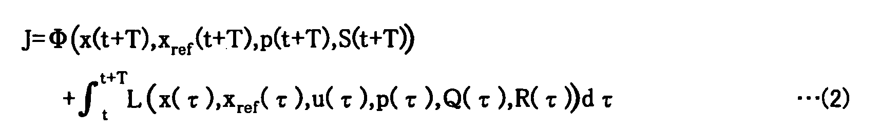
- In this performance index, appropriate functions are selected for Φ and L, appropriate values are set for S, Q and R, and u(t) which minimizes the performance index is obtained. Then, an operation command value for the actuators is calculated, using u(t) as a command value for thrust for the ship. This arithmetic operation is performed in real time. In this performance index, the first term is for evaluating the state at a future time which comes a specified time after the present time, and the second term is for evaluating the state variables and manipulated variables (thrust) over a specified period of time from the present time to the future time.
- The weights S, Q and R of the performance index are variant so that their values can be arbitrary changed depending on data on the KEEP OUT zone, the distance to the way point WP serving as the destination point and user's instructions.
- In the present embodiment, the following equation (3) is defined as a preferable concrete example of the performance index of the equation (2).

- Herein, x1=x, x2=u, x3=y, x4=v, x5=ψ, x6=r, x7=X, x8=Y x9=N, u1=Xr, u2=Yr, and u3=Nr. They conform to the following dynamic equations.
- Herein, the equations (10) to (12) are the approximate expressions of the dynamic characteristics of the thrust allocation unit 9 and the actuators 4 shown in Figure 2. Although each dynamic characteristic is approximated by a primary delay system herein, the approximation is not limited to this but an arbitrary equation may be employed.
- As shown in Figures 4 and 5, the parameters of the equations (3) to (12) are as follows.
- x: the x coordinate of the center of the ship; y: the y coordinate of the center of the ship; Ψ: the heading angle of the ship; u: the speed of the ship in a fore-off direction (longitudinal direction); v: the speed of the ship in a lateral direction (widthwise direction); r: the angular speed of the ship; X: a thrust working on the ship in its fore-off direction; Y: a thrust working on the ship in its lateral direction; N: a moment about the center of the ship; Xr: a command value indicative of a thrust to be exerted in the fore-off direction of the ship; Yr: a command value indicative of a thrust to be exerted in the lateral direction of the ship; Nr: a command value indicative of a moment about the center of the ship; M: the mass of the ship; mx: an added mass in the fore-off direction; my: an added mass in the lateral direction; Izz: a moment of inertia; Jzz: an added moment of inertia; XG: the distance between the center and gravity point of the ship; XH: a fluid force working on the ship in its fore-off direction; YH: a fluid force working on the ship in its lateral direction; NH: a fluid moment working around the center of the ship; Kx, Ky, Kn: coefficients representative of an amplitude ratio of output from input; Tx, Ty, Tn: coefficients representative of a time constant of the first order time delay.
- As discussed earlier, the weights Sfi, qi, ri of the performance index of the equation (3) are variant, so that their values are changed according to data on KEEP OUT zones, the distance to a way point WP serving as the destination point, the degree of a route constraint and others.
- For example, if a region 201 which is off-limits for ships (e.g., KEEP OUT zones) exists beside a route 101, a weight q3 for y is set taking account of the region 201 as shown in Figure 6(b). More specifically, with respect to the direction of the yi axis in a local coordinate system, the weight q3 is set to take a constant value V0 within the area where the region 201 does not exist and to rapidly increase in the area where the region 201 exists.
- In this case, a zone A1 where the value of the weight is constant and a zone A2 where the value of the weight increases are set based on the route 101, taking account of the condition of the deviation (i.e., the difference between the state variables at the destination point and the state variables at the present location). Since the weight does not take discrete values, the weight is set to have continuous values. The zone A1 where the weight has a constant value is changed according to, for instance, the distance to the way point WP serving as the destination point. The degree of a constraint to the route 101 is adjusted, depending on the length of the zone A1 where the weight has a constant value.
- The degree of this constraint can be set so as to vary continuously, but, in the present embodiment, it is divided into, for example, five levels, "Non", "Loose", "Middle", "Tight", "Strict", in proportion to the length of the zone A1 where the weight has a constant value, as shown in Figure 7.
- The lower limit value V0 of the weight is changed depending on the distance to the way point WP serving as the destination point or the like. The zone A2 where the weight increases can be set for both the starboard side and port side of the ship. The degree of the route constraint may be set by changing the weight for other state variables such as the heading angle or speed of the ship, similarly to the case where the weight for the position of the ship is changed.
- Next, the operation of the ship maneuver system 1 having the above structure (the ship maneuver method) will be described. Figures 8(a),8(b) are views each showing a controlled state of a ship, wherein Figure 8(a) shows a present embodiment whereas Figure 8(b) shows a prior art example.
- Referring to Figures 1 to 4, the route data input device 2 sends way points WP, the state variables at the destination point, the leading distance D of the guide point and weights (including the degree of a route constraint) for each section 102 and the like to be input to the control unit 3 for setting. Then, the route optimizing operation unit 8 calculates, in real time, a two-directional force (thrust commands Xr, Yr) and a moment (thrust command Nr) which minimize the performance index of the equation (3). These calculated thrust commands are allocated to the individual actuators 21 to 25 of the actuators 4 by the thrust allocation unit 9, and the allocated thrust commands are output to the actuators 4 as operation commands. Then, the individual actuators 21 to 25 output thrusts based on the operation commands. According to the output thrusts, the ship 5 moves. During this time, the position detecting device 6 and the heading angle detecting device 7 measure the position and heading angle of the ship 5 respectively and the observer 10 inputs the present state variables based on the measured position, the measured heading angle and the operation commands output from the thrust allocation unit 9 to the route optimizing operation unit 8. As a result, the ship 5 is controlled so as to track an optimum route from the present location to the way point WP serving as the destination point, as shown in Figure 8(a). When the guide point GP shown in Figure 4 has reached the way point WP serving as the destination point, the route optimizing operation unit 8 switches the destination point to the next way point WP and controls the ship 5 similarly. At that time, the degree of the route (101) constraint imposed on the ship 5 varies according to the weights for the performance index set for every section 102.
- The following is understood from the comparison between the control of the present embodiment and the control of the prior art: In the prior art, the ship is controlled so as to null the deviation from the target value as shown in Figure 8(b) and therefore the ship sails, outputting necessary power to null the deviation even if disturbances such as winds and currents affect on the ship, so that a great amount of power is consumed. In contrast with this, the present embodiment is designed such that the ship is controlled while calculating an optimum route to the destination point in real time, so that even if disturbances occur, the ship can track the optimum route with power minimized in compliance with given conditions, provided that the ship sails within a preset constraint degree range.
- Next, the degree of the route (101) constraint on the ship 5 will be explained according to examples based on simulations.
- Figure 9 shows a simulation result associated with Example 1. In Figure 9, the abscissa represents the x coordinate whereas the ordinate represents the y coordinate. Thick lines represent the target position and target heading angle of the ship 5 at the way points WP0 and WP1, respectively. While the ship 5 moves from the way point WP0 to the way point WP1 (with its position changing), the heading angle of the ship 5 changes from the heading angle at the way point WP0 to the heading angle at the way point WP1.
- Where the optimizing control is performed by use of a performance index in which each term is weighed like the equations (1) and (3), if the weights are increased, the performance index increases with the increase in the weights, so that the state of the ship does not become close to the zone where the weights increase. In this example, the weights for the position and heading angle of the ship 5 are set to increase, but the constraint level for them is set to "Loose" (small: see Figure 7) and therefore the degree of the route constraint due to the weights is small. Therefore, the ship 5 moves from the way point WP to the way point WP1, tracking a course that is relatively distant from the route 101.
- Figure 10 shows a simulation result associated with Example 2. In Figure 10, the abscissa represents the x coordinate whereas the ordinate represents the y coordinate. In this example, the constraint level with respect to the position of the ship is set to "Strict" (extremely great: see Figure 7), the constraint level with respect to the heading angle of the ship is set to "Loose" (small). Accordingly, the ship 5 substantially sails on the route 101, moving from the way point WP0 to the way point WP1.
- Figure 11 shows a simulation result associated with Example 3. In Figure 11, the abscissa represents the x coordinate whereas the ordinate represents the y coordinate. In this example, the level of the constraint to the position of the ship is set to "Middle" (middle: see Figure 7) and the level of the constraint to the heading angle of the ship is set to "Loose" (small). Therefore, the ship 5 tracks a course that is slightly distant from the route 101, moving from the way point WP0 to the way point WP1.
- Figure 12 shows a simulation result associated with Example 4. In Figure 12, the abscissa represents the x coordinate whereas the ordinate represents the y coordinate. In this example, the levels of the constraints to the position of the ship and to the heading angle of the ship are both set to change from "Loose" (small) to "Strict" (extremely great). Therefore, the ship 5 is substantially located on the route 101 and its heading angle becomes close to the target heading angle at the way point WP1 when it sails on the way from the way point WP0 to the way point WP1. When sailing from there to the way point WP1, the ship substantially tracks the route 101 with its heading angle slightly changing.
- As apparent from the foregoing examples 1 to 4, with the control of the present embodiment, the ship 5 can be moved between way points WP, taking a desired course and attitude, by appropriately setting weights for the position and heading angle of the ship 5. These weights can be readily set by the operator's sensuous judgement.
- Next, automatic mooring will be explained by way of an example based on a simulation.
- Figure 13 diagrammatically illustrates a shipping route employed in the simulation of Example 5. Figure 14 illustrates a simulation result according to Example 5. In Figure 14, the abscissa represents the x coordinate whereas the ordinate represents the y coordinate.
- As shown in Figure 13, in the simulation of this example, a jetty 302 having an opening 302a at its center is located in the port and a pier 301 is located at the right far side of the opening 302a. A first way point WP0 is set at the approximate center of the opening 302a of the jetty 302, and a second way point WP 1 is set on the left hand of the pier 301 in front of the opening 302a. Third to fifth way points WP2 to WP4 are set to depart from the second way point WP 1, surrounding the leading end of the pier 301. A sixth way point WP5 is set alongside the pear 301 at a position straight ahead of the fifth way point WP4. The heading angle of the ship 5 at the first to third way points WP0 to WP2 is the same as the heading angle which the ship takes when coming into the port and the heading angle of the ship 5 at the fourth and sixth way points WP3 to WP5 is opposite to the heading angle at the time of entry into the port.
- In this example, the level of the constraint to the position of the ship 5 is set to "Loose" (small) for all the sections 102. The level of the constraint to the heading angle of the ship 5 is set to "Loose" for the section 102 between the fifth way point WP4 and the sixth way point WP5 and to "Non" (nothing: See Figure 7) for other sections 102. As a result, when the ship 5 was sailing from the third way point WP2 to the fourth way point WP3, it came near the pier 301, deviating from the route 101, and when the ship 5 came alongside the pier 301, it made a big turn, hitting the pier 301. The result was thus undesirable.
- Figure 15 shows a simulation result associated with Example 6. In Figure 15, the abscissa represents the x coordinate whereas the ordinate represents the y coordinate. In this example, the levels of the constraints to the position of the ship 5 and to the heading angle of the ship 5 are both set to "Loose" (small) for all the sections 102. As a result, a collision between the ship 5 and the pier 301 could be avoided, but the ship 5 made a turn with a large radius while sailing from the third way point WP2 to the fourth way point WP3 so that the bow of the ship excessively came close to the jetty 302, causing a dangerous situation.
- Figure 16 shows a simulation result associated with Example 7. In Figure 16, the abscissa represents the x coordinate whereas the ordinate represents the y coordinate. In this example, the level of the constraint to the position of the ship 5 was set to "Strict" (extremely great) for all the sections 102. The level of the constraint to the heading angle of the ship 5 was set to "Loose" (small) for the section 102 between the first way point WP0 and the second way point WP1; set to change from "Loose" (small) to "Strict" (extremely great) for each section 102 between the second way point WP1 and the fifth way point WP4; and set to "Strict" (extremely great) for each section 102 between the fifth way point WP4 and the six way point WPS. As a result, the ship 5 substantially sailed on the route 101 between the third way point WP2 and the fourth way point WP3 and turned in the vicinity of the fourth way point 3, so that the risk that the bow came close to the jetty 302 could be avoided and a good result was obtained.
- It will be apparent from the foregoing examples 5 to 7 that the control of the present embodiment enables adequate automatic mooring of the ship 5 by properly setting a route and properly selecting weights for the position and heading angle of the ship 5.
- A second embodiment of the present invention exemplifies the preferred HMI.
- Figures 17(a) to 17(d) are diagrammatic views each illustrating an HMI route setting screen (an image of screen) according to the present embodiment, wherein Figure 17(a) shows setting of a KEEP OUT zone, Figure 17(b) shows a state in which a route has been partly set, and Figure 17(c) shows a state in which setting of a route has been completed.
- The HMI of this embodiment is constituted by, as previously discussed in the first embodiment, a display unit such as a display connected to the control unit 3 (computer: see Figure 1) and an input device such as a mouse and a key board. Setting of desired items in a computer by inputting specified data with an input device while a specified screen being displayed on the screen of the display unit is generally known, and therefore, the following discussion on a route and setting of the degree of the route constraint will be presented in conjunction with the setting screens alone and the software will not be discussed.
- As shown in Figure 17(a), according to the present embodiment, a route setting screen is first displayed on the display unit and then, KEEP OUT zones such as the obstacles 301, 302 are manually set, operating the mouse or the like on the setting screen. It is also possible to automatically set the KEEP OUT zones by inputting GPS data or MAP data to the control unit 3.
- Thereafter, the way points WP0 to WP5 are specified by operating the mouse, as shown in Figures 17(b) and 17(c). Then, the position data on the way points WP0 to WP5 is transferred to and stored in the control unit 3 (setting). The way points WP0 to WP5 are sequentially connected by straight lines which are, in turn, displayed on the screen. In this way, a route is set.
- Next, setting of the degree of the route constraint will be explained. Figure 18 diagrammatically shows setting of the degree of the route constraint.
- As shown in Figure 18, after a desired section 102 has been clicked on a screen 401 (corresponding to the screen shown in Figure 17(c)) wherein route setting has been completed, a screen 402 is displayed for setting the degree of the route constraint for the section 102. On the screen 402, slide bars ((403a, 403b), (404a, 404b)) for use in setting the degree of a constraint to the position of the ship are displayed beside way points WPi, WPi+1, respectively, on the starting point side and terminal point side of the section 102. Rotating bars ((405, 406), (407a, 407b), (408a, 408b)) for use in setting the degree of a constraint to the heading angle of the ship are displayed on the way points WPi, WPi+1, respectively, on the starting point side and terminal point side of the section 102. Further, a slide bar 411 used for setting a speed limit (the maximum speed value) for the ship is displayed at an appropriate position on the screen. After the slide bars 403a, 403b for the starting point side and the terminal point side have been positioned at their respective desired positions, a straight line 403c connecting the positions of the slide bars 403a and 403b is displayed. The positions of the slide bars 403a, 403b and the straight line 403c indicate the positions at each of which the weight starts to increase in relation to a deviation from the route 101 to port (a deviation in the y-direction). In this way, the degree of the constraint to the position of the ship with respect to the port side of the ship, i.e., the y direction is set. After the slide bars 404a, 404b for the starting point side and the terminal point side have been positioned at their respective desired positions, a straight line 404c connecting the positions of the slide bars 404a, 404b is displayed. The positions of the slide bars 404a, 404b and the straight line 404c indicate the positions at each of which the weight starts to increase in relation to a deviation from the route 101 to starboard (a deviation in the y-direction). In this way, the degree of the constraint to the position of the ship with respect to the starboard side of the ship, i.e., the y direction is set.
- The rotation angles of the rotating bars 405, 406 on the starting point side and the terminal point side indicate target heading angle values at the way points on the starting point side and on the terminal point side, respectively. By positioning the rotating bars 405, 406 at their respective desired rotation angles, target heading angle values at the way points on the starting point side and on the terminal point side can be set. The rotation angles of the rotating bar 407a on the starting point side and the rotating bar 407b on the terminal point side indicate the heading angles at each of which the weight for the port deviation of the heading angle from the target angle at the way point on the starting point side (the terminal point side) increases. Accordingly, by positioning the rotating bars 407a, 407b at their respective desired rotation angles, the degrees of the constraint to the port deviation of the heading angle of the ship at the way points on the starting point side and on the terminal point side are set. The rotation angles of the rotating bar 408a on the starting point side and the rotating bar 408b on the terminal point side indicate the heading angles at each of which the weight for the starboard deviation of the heading angle from the target angle at the way point on the starting point side (the terminal point side) increases. Accordingly, by positioning the rotating bars 408a, 408b at their respective desired rotation angles, the degrees of the constraint to the starboard deviation of the heading angle of the ship at the way points on the starting point side and on the terminal point side are set. Although not shown in the present embodiment, the degree of the constraint to the heading angle of the ship can be set so as to change as described later by a specified operation, when the ship is sailing from the starting point side to the terminal point side in an arbitrary section.
- The position of the slide bar 411 indicates the speed at which the weight for the speed of the ship starts to increase. Therefore, the maximum value of the speed of the ship can be set by positioning the slide bar 411 at a desired position.
- Data on the degrees of various constraints thus set is transferred to and stored in the control unit 3 (See Figure 1). The aforesaid bars 403 to 409 and 411 are operated, for example, by a mouse.
- Figures 19(a) to 19(g) are diagrammatical views showing examples of setting of weights for a position and for an heading angle, wherein Figures 19(a) to 19(c) show examples of setting of a weight for a position, Figure 19(d) shows an example of setting of the lengths of constant weight zones as functions of a distance to a way point serving as the destination point, and Figures 19(e) to 19(g) show examples of setting of a weight for an heading angle.
- In the present embodiment, weights for the position with respective to the y direction on the above-described starting point side and terminal point side are set as shown in Figures 19(b), 19(c). The lengths Wrs, Wls, Wre, Wle of the constant weight zones on the starting point side and terminal point side correspond to the positions of the slide bars 404a, 403a, 404b, 403b, respectively, shown in Figure 18. The lengths Wr, Wl of the constant weight zones on the starboard side and the port side are set so as to vary relative to the distance (i.e., the position with respect to the x direction) to the way point WPi+1 serving as the destination point as shown in Figure 19(d). The straight lines, which are indicative of changes in the lengths Wr, Wl of the constant weight zones on the starboard side and the port side relative to the position with respect to the x direction, correspond to the straight lines 404c, 403c shown in Figure 18. In this embodiment, a weight for the position with respect to the x direction can be set as shown in Figure 19(a). The weight for the position with respect to the x direction may be a constant value. Where the weight is varied, it is set, for example, as a function of the degree of the constraint to the position with respect to the y direction on the starboard side or port side.
- In the present embodiment, weights for heading angles on the starting point side and terminal point side are set as shown in Figures 19(e) and 19(f) respectively. The lengths Rrs, Rls, Rre, Rle of the weight constant zones on the starting point side and terminal point side correspond to the difference between the heading angles of the rotating bars 408a, 407a, 408b, 407b and their respective target values. The lengths Rr, Rl of the constant weight zones where the weight is constant when the ship turns to starboard or port are set to vary relative to the distance (i.e., the position with respect to the x direction) to the way point WPi+1 serving as the destination point, as shown in Figure 19(g).
- Figure 20 shows a method of drawing a curve indicative of changes in a weight for an arbitrary state variables. As shown in Figure 20, this curve is prepared in such a way that a plurality of points each of which indicates a weight value are first plotted and then, these points are connected with an approximate curve.
- Figures 21(a) to 21(p) show examples of the curve prepared through such a process, each of which is indicative of changes in a weight relative to a state variables.
- In a third embodiment of the invention, the route 101 shown in Figure 4 associated with the first embodiment has only two way points, that is, a starting point and a terminal point, and these two way points are set to the same point. With this arrangement, the ship 5 is controlled so as to be kept at a fixed point. In addition, this control can be performed with the same algorithm (procedure) as in the case where the ship sails along the route 101, so that the control unit can be simplified.
- In a fourth embodiment of the invention, the guide point GP of the first embodiment shown in Figure 4 is set as the destination point. In this case, the local coordinate system and the degree of the route constraint are updated in real time. This arrangement obviates the need for setting way points.
- Figures 22(a),22(b) are views showing the operation and structure of a ship maneuver system according to a fifth embodiment of the invention, wherein Figure 22(a) shows an action for avoiding an obstacle, whereas Figure 22(b) shows changes in a weight for a position with respect to the y direction.
- In the present embodiment, the ship maneuver system 1 (see Figure 1) includes an obstacle detector 1. The obstacle detector is composed of a radar, an ultrasonic sonar or the like. In Figure 22(a), reference numeral 502 designates an obstacle detectable range for the obstacle detector. If the obstacle detector detects an obstacle 501 near the ship 5, the control unit 3 (see Figure 1) sets a weight for the position with respect to the y direction such that it increases, as shown in Figure 22(b), short of the region where the obstacle 501 exists. Specifically, the weight for the position with respect to the y direction is updated in real time based on data on an obstacle. With this arrangement, the ship 5 moves so as to avoid the obstacle 501 as shown in Figure 22(a). As a result, the ship 5 automatically avoids the obstacle 501 near the route 101 and sails safely.
- In a sixth embodiment of the invention, the weights of the performance index are set as a function of time. For example, if the weight for the speed of the ship is set to change after an elapse of a certain time, the ship will change its speed after an elapse of the certain time. Accordingly, the ship can be automatically stopped or started by properly setting the weight.
- According to a seventh embodiment of the invention, if an event is detected, the speed of the ship will be changed.
- In a first arrangement, the weights of the performance index are set as a function of an event signal. For instance, in Figure 2 associated with the first embodiment, the control unit 3 is designed such that if an operation button has been pressed, the sensor detects it to issue a specified signal (event signal). After the specified signal has been input to the route optimizing operation unit 8, the weight for the speed of the ship is set to vary. With this arrangement, the speed of the ship is changed by pressing the operation button so that the ship can be started or stopped.
- In a second arrangement, if the event signal has been input to the route optimizing operation unit 8, the destination point is switched between other points (e.g., the present destination point (the next way point WP)) than the present location and the present location. With this arrangement, if the operation button is pressed while the ship is sailing, the ship will stop and if the operation button is pressed while the ship is stopped, the ship will start to move.
- Strictly speaking, if the destination point is switched to the present location in this case, the ship goes past the destination point after switching owing to the dynamic characteristics of the ship so that control is performed so as to make the ship return. As a result, the timing of stopping delays to that extent. It is therefore preferable to take the following measure: the position at which the ship will stop if a specified thrust is exerted, at the present time, in a direction opposite to the heading direction of the ship is predicted, taking account of the dynamic characteristics of the ship and the destination point is switched to the predicted position. With this arrangement, the ship can be brought to a stop in a shorter time. In this case, the ship can be started by switching the destination point to any of points other than the above predicted point.
- An eighth embodiment of the invention is associated with maneuver of movable objects other than ships. As apparent from the equations (1) to (12) of the first embodiment, the optimizing control with the performance index of the equation (3) is applicable not only to ships but also to other general movable objects. The equations (3) to (12) can be applied without change, especially to cases where a movable object moves within a two-dimensional space under the force or moment of resistance, friction and the like. In cases where a movable object moves within a three-dimensional space under fluid resistance, state variables and thrusts (manipulated variables) associated with the position with respect to the z direction, heading angle in the x-z plane and heading angle in the y-z plane are added to the performance index of the equation (3), and a term relating to the z axis is added to the dynamic equations (4) to (9), whereby these equations can be applied to the control of a movable object moving in a three-dimensional space.
- With this arrangement, even if disturbances affect the movable object, it can be automatically steered so as to move along a route while minimizing power in compliance with given conditions.
- Example 8 is associated with an application of the present invention to maneuver of an aircraft.
- Figure 23 is a block diagram showing a structure of the control system of an aircraft maneuver system according to the present example. Figure 24 shows an aircraft model and the definitions of state variables according to the present example. It should be noted that the reference numerals common to Figures 1 and 23 represent the same or equivalent parts.
- As shown in Figure 23, an object to be controlled by an aircraft maneuver system 601 of the present example is an aircraft 602, and the aircraft maneuver system 601 has an Euler angle detecting device 603 in place of the heading angle detecting device 7 provided for the ship maneuver system 1 shown in Figure 1. Except the above points, the aircraft maneuver system 601 is similar to the ship maneuver system 1. The Euler angle detecting device 603 is composed of, for example, a directional gyro and measures the Euler angles of the aircraft to output as Euler angle data.
- As shown in Figure 24, the following eighteen state variables are defined in the aircraft model employed in the aircraft body control of the present example.
- (x, y, z): the position of the gravity point of the aircraft body in the global fixed coordinate system
- (u, v, w): the body fixed coordinate axis components of the speed vector of the aircraft body
- (p, q, r): the body fixed axis components of the angular speed of the aircraft body
- (Θ,Φ,Ψ): Euler angles (the angles that define the orientation of the body axis with respect to the ground fixed coordinate system)
- (X, Y, Z): thrusts for translational motion
- (L, M, N): thrust moments for rotating motion
-
- In contrast with the state variables of the first embodiment (Figure 5), the state variables of Example 8 include state variables with respect to the z-axis and Euler angles (Θ,Φ,Ψ).
- The dynamic equation of the aircraft model is as follows.
- The performance index for the non-linear optimizing control of the present example is set as represented by Equation (31).where Xref is a target state, that is, the position and state of the aircraft body at a way point WP serving as the destination point.

- Figure 25 diagrammatically shows an example of setting of an aircraft flight course in the aircraft body control of Example 8.
- As shown in Figure 25, one or more way points WP are set in a three-dimensional space (space above the ground) represented by three-dimensional coordinates composed of an east-west axis, south-north axis and altitude axis which intersect with one another at right angles. The way points thus set are connected with straight lines, thereby determining a flight course 604. Herein, a guidance route for aircraft landing is shown.
- Figure 26 shows a simulation result of the aircraft body control of Example 8. There is shown, herein, a result of a simulation where the aircraft takes the guidance route 604 shown in Figure 25. As seen from Figure 26, the aircraft 602 can be automatically steered so as to take the optimal route 605, by the aircraft body control of the present example.
- Example 9 is associated with an application of the present invention to maneuver of an underwater craft.
- Figure 27 is a table showing the definitions of the state variables of an underwater craft according to the present example. The following equation represents the relationship between the Euler angle expression and directional cosine matrix expression of the attitude angle of the ship, regarding the state variables [C] shown in Figure 27.

- It should be noted that the underwater craft serving as the controlled object of the present example is a submarine.
- The dynamic equation for this underwater craft model is as follows.


- The state variables of Example 9 differ in code from, but are substantially the same as those of Example 8. Specifically, [FWA], [FTH], [FP] correspond to X, Y, Z, L, M and N of Example 8.
- The performance index for the non-linear optimizing control of the present example is determined, similarly to Example 8.
- Next, a simulation result of the ship control of the present example will be explained in comparison with the ship control according to the conventional PID control law.
- Figures 28(a),28(b),29(a) and 29(b) are views each showing a simulation result of the ship control according to the conventional PID control law. Figure 28(a) shows a ship trajectory and Figure 28(b) shows variations in horizontal rudder angle, vertical ruder angle, and diving rudder angle (they are hereinafter referred to as "rudder angles"). Figure 29(a) shows variations in roll angle, pitch angle and yaw angle (they are hereinafter referred to as "attitude angles"). Figure 29(b) shows variations in ship speed and yaw rate.
- Figures 30(a),30(b),31(a) and 31(b) are views each showing a simulation result of the ship control according to Example 9. Figure 30(a) shows a ship trajectory and Figure 30(b) shows variations in rudder angles. Figure 31(a) shows variations in attitude angles and Figure 31(b) shows variations in ship speed and yaw rate.
- According to these simulation results, the ship control based on the conventional PID control law is unable to make the ship turn rapidly as apparent from Figure 28(a), whereas the ship control according to the present example enables a rapid turn of the ship as apparent from Figure 30(a).
- Numerous modifications and alternative embodiments of the invention will be apparent to those skilled in the art in view of the foregoing description. Accordingly, the description is to be construed as illustrative only, and is provided for the purpose of teaching those skilled in the art the best mode of carrying out the invention. The details of the structure and/or function may be varied substantially without departing from the spirit of the invention.
Claims (44)
- A method of maneuvering a movable object, comprising:setting a destination point;calculating a thrust value in real time which minimizes or maximizes a performance index associated with one or more state variables and thrust required for a movable object to reach the destination point and which takes into account non-linear conditions inherent to the movable object, andmoving the movable object based on the calculated thrust value.
- The method according to claim 1, wherein the thrust value is calculated in real time which minimizes or maximizes the performance index over a specified period of time from the present time to a future time.
- A method of maneuvering a movable object, comprising:setting a destination point;calculating a thrust value in real time which minimizes or maximizes a performance index associated with thrust required for a movable object to reach the destination point;moving the movable object based on the calculated thrust value;setting one or more transit points on a planned route for the movable object;and sequentially setting one or more set transit points as the destination point.
- The method according to claim 3, wherein the thrust value is calculated in real time which minimizes or maximizes the performance index over a specified period of time from the present time to a future time.
- The method according to any one of claim 3, wherein the performance index includes weights for the state variables, the thrust and each term, wherein the weights are set as constraints which limit the values of the state variables and the thrust, and wherein the thrust value restricted by the set constraints is calculated.
- The method according to claim 3, wherein the planned route includes only two transit points which are a starting point and a terminal point, and the two transit points are set to the same point.
- The method according to claim 3, wherein a guide point is set which consists of a virtual point and moves on the planned route, preceding the movable object, and wherein when the guide point has reached a transit point which is the present destination point, the destination point is switched to the next transit point.
- The method according to claim 3, wherein the performance index includes weights for the state variables, the thrust and each term, wherein the weights are set for each zone of the planned route as constraints which limit the values of the state variables and the thrust, each zone being defined by the transit points and wherein the thrust value restricted by the constraints corresponding to each transit point is calculated.
- The method according to claim 5, wherein the weights are set as constants.
- The method according to claim 5, wherein the weights are set as function of positions.
- The method according to claim 5, wherein the weights are set as functions of the position and attitude of the movable object.
- The method according to claim 5, wherein the weights are set as functions of deviation from the state variables at the destination point.
- The method according to claim 5, wherein the weights are set as function of speeds.
- The method according to claim 5, wherein the weights are set as function of times.
- The method according to claim 5, wherein the weights are set as functions of an event signal.
- The method according to claim 5, wherein the weights are set as functions of data on obstacles.
- The method according to claim 1, wherein upon detection of an event, the destination point is set by switching between the present location and any of other points than the present location.
- The method according to any one of claims 1, wherein the performance index includes the state variables and the thrust as variables and wherein the state of the movable object is estimated, using a non-linear or linear state observer.
- The method according to any one of claims 1, wherein necessary items including the destination point and the performance index are set using a human-machine interface.
- A system for maneuvering a movable object, comprising:means for setting a destination point;arithmetic operation means for calculating a thrust value in real time which minimizes or maximizes a performance index associated with one or more state variables and thrust required for a movable object to reach the destination point and which takes into account non-linear conditions inherent to the movable object; andactuators for moving the movable object based on the calculated thrust value.
- The system according to claim 20, wherein the arithmetic operation means calculates the thrust value in real time which minimizes or maximizes the performance index over a specified period of time from the present time to a future time.
- A system for maneuvering a movable object, comprising: means for setting a destination point; arithmetic operation means for calculating a thrust value in real time which minimizes or maximizes a performance index associated with thrust required for a movable object to reach the destination point; and actuators for moving the movable object based on the calculated thrust value,
the system further comprising means for setting a planned route for the movable object and one or more transit points on the planned route,
wherein one or more set transit points are sequentially set as the destination point. - The system according to claim 22, wherein the arithmetic operation means calculates the thrust value in real time which minimizes or maximizes the performance index over a specified period of time from the present time to a future time.
- The system according to any one of claims 22,
wherein the performance index includes weights for the state variables, the thrust and each term,
which further comprises means for setting the weights as constraints which limit the values of the state variables and the thrust, and
wherein the arithmetic operation means calculates the thrust value restricted by the set constraints. - The system according to claim 22, wherein the planned route includes only two transit points which are a starting point and a terminal point, and the two transit points are set to the same point.
- The system according to claim 22, further comprising means for setting a guide point which consists of a virtual point and moves on the planned route, preceding the movable object,
wherein when the guide point has reached a transit point which is the present destination point, the destination point is switched to the next transit point. - The system according to claim 22,
wherein the performance index includes weights for the state variables, the thrust and each term,
which further comprises means for setting the weights for each zone of the planned route as constraints which limit the values of the state variables and the thrust, each zone being defined by the transit points and
wherein the arithmetic operation means calculates the thrust value restricted by the constraints corresponding to each transit point. - The system according to claim 22, wherein the weights are set as constants.
- The system according to claim 24, wherein the weights are set as function of positions.
- The system according to claim 24, wherein the weights are set as functions of the position and attitude of the movable object.
- The system according to claim 24, wherein the weights are set as functions of deviation from the state variables at the destination point.
- The system according to claim 24, wherein the weights are set as function of speeds.
- The system according to claim 24, wherein the weights are set as function of times.
- The system according to claim 24, wherein the weights are set as functions of an event signal.
- The system according to claim 24, wherein the weights are set as functions of data on obstacles.
- The system according to claim 24 further comprising means for detecting an event,
wherein upon detection of an event, the destination point is set by switching between the present location and any of other points than the present location. - The system according to any one of claims 22,
wherein the performance index includes the state variables and the thrust as variables, and
which further comprises a non-linear or linear state observer for estimating the state of the movable object. - The system according to any one of claims 22, further comprising a human-machine interface for setting necessary items including the destination point and the performance index.
- The method according to any one of claims 3, wherein the movable object is a ship.
- The method according to any one of claims 3, wherein the movable object is an underwater craft.
- The method according to any one of claims 3, wherein the movable object is an aircraft.
- The system according to any one of claims 22, wherein the movable object is a ship.
- The system according to any one of claims 22, wherein the movable object is an underwater craft.
- The system according to any one of claims 22, wherein the movable object is an aircraft.
Applications Claiming Priority (4)
| Application Number | Priority Date | Filing Date | Title |
|---|---|---|---|
| JP2002144878 | 2002-05-20 | ||
| JP2002144878 | 2002-05-20 | ||
| JP2003136373 | 2003-05-14 | ||
| JP2003136373A JP4301861B2 (en) | 2002-05-20 | 2003-05-14 | Method and apparatus for maneuvering moving body |
Publications (3)
| Publication Number | Publication Date |
|---|---|
| EP1365301A2 true EP1365301A2 (en) | 2003-11-26 |
| EP1365301A3 EP1365301A3 (en) | 2005-02-23 |
| EP1365301B1 EP1365301B1 (en) | 2016-04-13 |
Family
ID=29405343
Family Applications (1)
| Application Number | Title | Priority Date | Filing Date |
|---|---|---|---|
| EP03011400.3A Expired - Lifetime EP1365301B1 (en) | 2002-05-20 | 2003-05-20 | Method and system for maneuvering a movable object |
Country Status (3)
| Country | Link |
|---|---|
| US (1) | US7366593B2 (en) |
| EP (1) | EP1365301B1 (en) |
| JP (1) | JP4301861B2 (en) |
Cited By (11)
| Publication number | Priority date | Publication date | Assignee | Title |
|---|---|---|---|---|
| EP1794547A2 (en) * | 2004-09-22 | 2007-06-13 | Kenneth Litvack | Navigation assistance method and system |
| WO2010077554A1 (en) * | 2008-12-29 | 2010-07-08 | General Electric Company | System and method for optimizing a path for a marine vessel through a waterway |
| WO2008100684A3 (en) * | 2007-02-15 | 2010-07-22 | The Boeing Company | System and method of facilitating navigation of vessels in specific water environments |
| DE102010008807A1 (en) | 2010-02-22 | 2011-08-25 | Engelskirchen, Jürgen, Dipl.-Ing., 22395 | Method for automatic remote controlling of controllable object on predetermined arbitrary virtual path, involves determining actual position of object on predetermined virtual path by one or multiple external sensors |
| EP2386480A1 (en) * | 2003-12-01 | 2011-11-16 | Rolls-Royce Naval Marine, Inc. | Control of a waterjet propelled vessel |
| EP2498056A1 (en) * | 2009-11-04 | 2012-09-12 | Kawasaki Jukogyo Kabushiki Kaisha | Maneuvering control method and maneuvering control system |
| RU2615849C1 (en) * | 2015-11-06 | 2017-04-11 | Федеральное государственное бюджетное образовательное учреждение высшего профессионального образования "Мурманский государственный технический университет" (ФГБОУ ВПО "МГТУ") | Moving vessel control method |
| RU174602U1 (en) * | 2016-11-11 | 2017-10-23 | Федеральное государственное бюджетное учреждение науки Институт проблем управления им. В.А. Трапезникова Российской академии наук | The system of automatic control of the movement of the vessel with the assessment of external disturbance |
| SE1751310A1 (en) * | 2017-10-23 | 2019-04-24 | Rolls Royce Ab | Navigation system with independent control of lateral and longitudinal thrust |
| EP3627106A3 (en) * | 2018-08-31 | 2020-06-24 | ABB Schweiz AG | Apparatus and method for maneuvering marine vessel |
| CN116841205A (en) * | 2023-07-14 | 2023-10-03 | 华中科技大学 | Method and system for controlling track tracking limited time preset performance of hand boat coupling system |
Families Citing this family (53)
| Publication number | Priority date | Publication date | Assignee | Title |
|---|---|---|---|---|
| JP4275442B2 (en) * | 2003-03-31 | 2009-06-10 | ヤマハ発動機株式会社 | Attitude angle control device, attitude angle control method, attitude angle control device control program, and cruise control device |
| NO318966B1 (en) * | 2003-05-26 | 2005-05-30 | Teekay Norway As | Method and device of a simulator for training the master of a vessel |
| US7386392B1 (en) | 2003-09-18 | 2008-06-10 | Garmin Ltd. | Methods, systems, and devices for condition specific alerts |
| US7268703B1 (en) * | 2003-09-18 | 2007-09-11 | Garmin Ltd. | Methods, systems, and devices for cartographic alerts |
| NO320841B1 (en) * | 2004-06-08 | 2006-01-30 | Marine Cybernetics As | Procedure for testing a combined dynamic positioning and power control system |
| JP5052165B2 (en) * | 2007-03-05 | 2012-10-17 | 東京計器株式会社 | Ship automatic steering system |
| GB2450469B (en) * | 2007-04-19 | 2009-12-02 | Ocean Technical Systems Ltd | Vessel mooring monitor |
| ES2324971B1 (en) * | 2008-02-19 | 2010-04-20 | Juan Mariano Bendito Vallori | EVASIVE AUTOMATIC PILOT SYSTEM FOR BOATS. |
| US8457889B2 (en) * | 2008-03-31 | 2013-06-04 | Honeywell International Inc. | Waypoint display system and method |
| US20100274420A1 (en) * | 2009-04-24 | 2010-10-28 | General Electric Company | Method and system for controlling propulsion systems |
| DE102009022652A1 (en) * | 2009-05-26 | 2010-12-09 | Philipp Gläser | Assistance system for the control of a ship |
| JP5431141B2 (en) * | 2009-12-18 | 2014-03-05 | ヤンマー株式会社 | Ship berthing support device |
| DE102010003031B4 (en) * | 2010-03-18 | 2012-09-06 | Knud Benedict | Method and device for integrated, simulation-based maneuver planning and execution on ships and in ship simulators |
| US20130201053A1 (en) * | 2012-02-03 | 2013-08-08 | Jeffrey Saing | Crash Avoidance System |
| CH707573A1 (en) * | 2013-02-07 | 2014-08-15 | Thomas Frizlen | Method and system for determining the displacement of an anchor. |
| US9248898B1 (en) | 2013-03-06 | 2016-02-02 | Brunswick Corporation | Systems and methods for controlling speed of a marine vessel |
| US9039468B1 (en) | 2013-03-06 | 2015-05-26 | Brunswick Corporation | Systems and methods for controlling speed of a marine vessel |
| US9377780B1 (en) * | 2013-03-14 | 2016-06-28 | Brunswick Corporation | Systems and methods for determining a heading value of a marine vessel |
| US8924054B1 (en) * | 2013-03-14 | 2014-12-30 | Brunswick Corporation | Systems and methods for positioning a marine vessel |
| AT514588B1 (en) * | 2013-08-29 | 2015-02-15 | Tech Universität Wien | Method for controlling a vehicle |
| US9540122B2 (en) * | 2013-11-27 | 2017-01-10 | Analytical Graphics Inc. | Maneuver processing |
| JP6038094B2 (en) * | 2014-10-17 | 2016-12-07 | 三菱重工業株式会社 | Ship propulsion performance prediction apparatus and method, and ship operation support system |
| EP3064967A1 (en) * | 2015-03-04 | 2016-09-07 | Sercel | Method for determining a collision free sail path of at least one vessel of a fleet of vessels, corresponding device, computer program product and non-transitory computer-readable carrier medium |
| US9857794B1 (en) * | 2015-07-23 | 2018-01-02 | Brunswick Corporation | System for controlling position and speed of a marine vessel |
| WO2017045116A1 (en) | 2015-09-15 | 2017-03-23 | SZ DJI Technology Co., Ltd. | System and method for supporting smooth target following |
| WO2017071143A1 (en) | 2015-10-30 | 2017-05-04 | SZ DJI Technology Co., Ltd. | Systems and methods for uav path planning and control |
| JP2017088120A (en) * | 2015-11-17 | 2017-05-25 | ヤマハ発動機株式会社 | Ship maneuvering control method and ship maneuvering control system |
| CN105675195B (en) * | 2016-02-03 | 2018-04-24 | 中国海洋石油总公司 | Working ship operation real-time analyzer based on attitude of ship measurement |
| US10322787B2 (en) | 2016-03-01 | 2019-06-18 | Brunswick Corporation | Marine vessel station keeping systems and methods |
| US10198005B2 (en) | 2016-03-01 | 2019-02-05 | Brunswick Corporation | Station keeping and waypoint tracking methods |
| US9952595B2 (en) * | 2016-03-01 | 2018-04-24 | Brunswick Corporation | Vessel maneuvering methods and systems |
| US10640190B1 (en) | 2016-03-01 | 2020-05-05 | Brunswick Corporation | System and method for controlling course of a marine vessel |
| US10353400B2 (en) * | 2016-05-23 | 2019-07-16 | Asustek Computer Inc. | Navigation system and navigation method |
| US10259555B2 (en) | 2016-08-25 | 2019-04-16 | Brunswick Corporation | Methods for controlling movement of a marine vessel near an object |
| US10473781B2 (en) | 2016-09-14 | 2019-11-12 | Garmin Switzerland Gmbh | Determining a boundary enclosing a region of interest for a body of water |
| US10488216B2 (en) * | 2016-11-21 | 2019-11-26 | Robert Bosch Gmbh | Method for operating a motor-driven sports device |
| US10671073B2 (en) | 2017-02-15 | 2020-06-02 | Brunswick Corporation | Station keeping system and method |
| CN107367279B (en) * | 2017-06-21 | 2020-05-22 | 集美大学 | High-precision navigation and berthing method for large ship |
| JP6958894B2 (en) * | 2017-06-28 | 2021-11-02 | 株式会社ゼロプラス | Automatic feeding system |
| US10429845B2 (en) * | 2017-11-20 | 2019-10-01 | Brunswick Corporation | System and method for controlling a position of a marine vessel near an object |
| US10324468B2 (en) | 2017-11-20 | 2019-06-18 | Brunswick Corporation | System and method for controlling a position of a marine vessel near an object |
| CN111433827B (en) | 2017-12-01 | 2022-07-22 | 古野电气株式会社 | Mobile information calculation device, mobile information calculation method, and storage medium |
| JP2019120494A (en) | 2017-12-28 | 2019-07-22 | 古野電気株式会社 | Navigation route generating device, navigation route generating method and navigation route generator program |
| US10437248B1 (en) | 2018-01-10 | 2019-10-08 | Brunswick Corporation | Sun adjusted station keeping methods and systems |
| US10625824B2 (en) | 2018-01-13 | 2020-04-21 | Thomas Frizlen | Method and system for determining displacement of an anchor |
| JP6563067B1 (en) * | 2018-04-18 | 2019-08-21 | 三菱電機株式会社 | Ship direction control device and direction control method |
| US10845812B2 (en) | 2018-05-22 | 2020-11-24 | Brunswick Corporation | Methods for controlling movement of a marine vessel near an object |
| US10633072B1 (en) | 2018-07-05 | 2020-04-28 | Brunswick Corporation | Methods for positioning marine vessels |
| US11530022B1 (en) | 2018-07-10 | 2022-12-20 | Brunswick Corporation | Method for controlling heading of a marine vessel |
| US10926855B2 (en) | 2018-11-01 | 2021-02-23 | Brunswick Corporation | Methods and systems for controlling low-speed propulsion of a marine vessel |
| US11198494B2 (en) | 2018-11-01 | 2021-12-14 | Brunswick Corporation | Methods and systems for controlling propulsion of a marine vessel to enhance proximity sensing in a marine environment |
| TWI714040B (en) * | 2019-03-27 | 2020-12-21 | 財團法人船舶暨海洋產業研發中心 | A vessel navigation system and navigation method thereof |
| RU2759068C1 (en) * | 2021-03-26 | 2021-11-09 | Федеральное государственное бюджетное образовательное учреждение высшего образования "Государственный морской университет имени адмирала Ф.Ф. Ушакова" | Method for automatic pilotage of ship |
Citations (5)
| Publication number | Priority date | Publication date | Assignee | Title |
|---|---|---|---|---|
| US4325123A (en) * | 1978-07-28 | 1982-04-13 | The Boeing Company | Economy performance data avionic system |
| US5457634A (en) * | 1986-02-06 | 1995-10-10 | The Boeing Company | Time-responsive flight optimization system |
| EP0990921A2 (en) * | 1998-09-30 | 2000-04-05 | Honeywell Inc. | Method and apparatus for annunciation of vehicle operational modes |
| WO2000065417A1 (en) * | 1999-04-23 | 2000-11-02 | Canadian Space Agency | Advanced ship autopilot system |
| US6266610B1 (en) * | 1998-12-31 | 2001-07-24 | Honeywell International Inc. | Multi-dimensional route optimizer |
Family Cites Families (15)
| Publication number | Priority date | Publication date | Assignee | Title |
|---|---|---|---|---|
| US4445179A (en) * | 1980-03-07 | 1984-04-24 | Michelotti Paul E | Aircraft minimum drag speed system |
| JPS58202197A (en) * | 1982-05-18 | 1983-11-25 | Kawasaki Heavy Ind Ltd | Steering system for ship of the like |
| DE3222054A1 (en) * | 1982-06-11 | 1983-12-15 | Schottel-Werft Josef Becker Gmbh & Co Kg, 5401 Spay | DEVICE FOR DETERMINING THE DIRECTION OF MOTION AND FORCE OF A WATER VEHICLE |
| US4532887A (en) * | 1983-05-02 | 1985-08-06 | General Motors Corporation | Life extension of catalyst predip baths |
| JP3535887B2 (en) | 1994-03-04 | 2004-06-07 | 古野電気株式会社 | Automatic steering method and device |
| US5491636A (en) * | 1994-04-19 | 1996-02-13 | Glen E. Robertson | Anchorless boat positioning employing global positioning system |
| US6691004B2 (en) * | 1995-07-31 | 2004-02-10 | Honeywell International, Inc. | Method for determining a currently obtainable climb gradient of an aircraft |
| US6171055B1 (en) * | 1998-04-03 | 2001-01-09 | Aurora Flight Sciences Corporation | Single lever power controller for manned and unmanned aircraft |
| US6496741B1 (en) * | 1999-03-25 | 2002-12-17 | Gregory J. Whiffen | Static/dynamic control for optimizing a useful objective |
| US6450112B1 (en) * | 1999-04-02 | 2002-09-17 | Nautronix, Inc. | Vessel control force allocation optimization |
| US6309266B1 (en) * | 1999-12-21 | 2001-10-30 | Peter G. Burke | Ship propulsion and steering systems |
| US6273771B1 (en) * | 2000-03-17 | 2001-08-14 | Brunswick Corporation | Control system for a marine vessel |
| JP4736158B2 (en) | 2000-04-07 | 2011-07-27 | ユニバーサル造船株式会社 | Ship navigation control system |
| US6622472B2 (en) * | 2001-10-17 | 2003-09-23 | Gateway Space Transport, Inc. | Apparatus and method for thrust vector control |
| US6691034B1 (en) * | 2002-07-30 | 2004-02-10 | The Aerospace Corporation | Vehicular trajectory collision avoidance maneuvering method |
-
2003
- 2003-05-14 JP JP2003136373A patent/JP4301861B2/en not_active Expired - Fee Related
- 2003-05-20 US US10/442,003 patent/US7366593B2/en active Active
- 2003-05-20 EP EP03011400.3A patent/EP1365301B1/en not_active Expired - Lifetime
Patent Citations (5)
| Publication number | Priority date | Publication date | Assignee | Title |
|---|---|---|---|---|
| US4325123A (en) * | 1978-07-28 | 1982-04-13 | The Boeing Company | Economy performance data avionic system |
| US5457634A (en) * | 1986-02-06 | 1995-10-10 | The Boeing Company | Time-responsive flight optimization system |
| EP0990921A2 (en) * | 1998-09-30 | 2000-04-05 | Honeywell Inc. | Method and apparatus for annunciation of vehicle operational modes |
| US6266610B1 (en) * | 1998-12-31 | 2001-07-24 | Honeywell International Inc. | Multi-dimensional route optimizer |
| WO2000065417A1 (en) * | 1999-04-23 | 2000-11-02 | Canadian Space Agency | Advanced ship autopilot system |
Cited By (18)
| Publication number | Priority date | Publication date | Assignee | Title |
|---|---|---|---|---|
| EP2386480A1 (en) * | 2003-12-01 | 2011-11-16 | Rolls-Royce Naval Marine, Inc. | Control of a waterjet propelled vessel |
| EP2386478A1 (en) * | 2003-12-01 | 2011-11-16 | Rolls-Royce Naval Marine, Inc. | Control of a waterjet propelled vessel |
| EP1794547A4 (en) * | 2004-09-22 | 2011-06-29 | Kenneth Litvack | Navigation assistance method and system |
| EP1794547A2 (en) * | 2004-09-22 | 2007-06-13 | Kenneth Litvack | Navigation assistance method and system |
| WO2008100684A3 (en) * | 2007-02-15 | 2010-07-22 | The Boeing Company | System and method of facilitating navigation of vessels in specific water environments |
| US8706329B2 (en) | 2007-02-15 | 2014-04-22 | The Boeing Company | Facilitating navigation of vessels in specific water environments |
| WO2010077554A1 (en) * | 2008-12-29 | 2010-07-08 | General Electric Company | System and method for optimizing a path for a marine vessel through a waterway |
| US8155811B2 (en) | 2008-12-29 | 2012-04-10 | General Electric Company | System and method for optimizing a path for a marine vessel through a waterway |
| EP2498056A4 (en) * | 2009-11-04 | 2014-05-07 | Kawasaki Heavy Ind Ltd | Maneuvering control method and maneuvering control system |
| EP2498056A1 (en) * | 2009-11-04 | 2012-09-12 | Kawasaki Jukogyo Kabushiki Kaisha | Maneuvering control method and maneuvering control system |
| DE102010008807A1 (en) | 2010-02-22 | 2011-08-25 | Engelskirchen, Jürgen, Dipl.-Ing., 22395 | Method for automatic remote controlling of controllable object on predetermined arbitrary virtual path, involves determining actual position of object on predetermined virtual path by one or multiple external sensors |
| RU2615849C1 (en) * | 2015-11-06 | 2017-04-11 | Федеральное государственное бюджетное образовательное учреждение высшего профессионального образования "Мурманский государственный технический университет" (ФГБОУ ВПО "МГТУ") | Moving vessel control method |
| RU174602U1 (en) * | 2016-11-11 | 2017-10-23 | Федеральное государственное бюджетное учреждение науки Институт проблем управления им. В.А. Трапезникова Российской академии наук | The system of automatic control of the movement of the vessel with the assessment of external disturbance |
| SE1751310A1 (en) * | 2017-10-23 | 2019-04-24 | Rolls Royce Ab | Navigation system with independent control of lateral and longitudinal thrust |
| EP3627106A3 (en) * | 2018-08-31 | 2020-06-24 | ABB Schweiz AG | Apparatus and method for maneuvering marine vessel |
| US11181915B2 (en) | 2018-08-31 | 2021-11-23 | Abb Schweiz Ag | Apparatus and method for maneuvering marine vessel |
| CN116841205A (en) * | 2023-07-14 | 2023-10-03 | 华中科技大学 | Method and system for controlling track tracking limited time preset performance of hand boat coupling system |
| CN116841205B (en) * | 2023-07-14 | 2024-02-23 | 华中科技大学 | Method and system for controlling track tracking limited time preset performance of hand boat coupling system |
Also Published As
| Publication number | Publication date |
|---|---|
| US20040006423A1 (en) | 2004-01-08 |
| JP4301861B2 (en) | 2009-07-22 |
| US7366593B2 (en) | 2008-04-29 |
| JP2004042884A (en) | 2004-02-12 |
| EP1365301B1 (en) | 2016-04-13 |
| EP1365301A3 (en) | 2005-02-23 |
Similar Documents
| Publication | Publication Date | Title |
|---|---|---|
| US7366593B2 (en) | Method and system for maneuvering movable object | |
| US8145371B2 (en) | Dynamic control system for a marine vessel | |
| US10795366B1 (en) | Vessel maneuvering methods and systems | |
| WO2021230356A1 (en) | Method for autonomously guiding vessel, program for autonomously guiding vessel, system for autonomously guiding vessel, and vessel | |
| JP4213518B2 (en) | Control method and control apparatus for moving body | |
| US5951607A (en) | Autonomous craft controller system for landing craft air cushioned vehicle | |
| JP2023024675A (en) | Route generating device | |
| JP6658220B2 (en) | Navigation control method and device | |
| JP7417538B2 (en) | Control target generation device and ship maneuvering control device | |
| Sæther | Development and testing of navigation and motion control systems for milliampere | |
| Ohtsu et al. | A fully automatic berthing test using the training ship Shioji Maru | |
| JP2749833B2 (en) | Control thrust distribution device | |
| JP2021076537A (en) | Pier docking support program for vessel, pier docking support system for vessel, and vessel equipped with pier docking support system for vessel | |
| JPH0578476B2 (en) | ||
| Salarieh et al. | Trajectory optimization for a high speed planing boat based on Gauss pseudospectral method | |
| Gauslaa | Navigation, guidance, and control for autonomous docking of ships | |
| Dewi et al. | Design control of autonomous surface vehicle position using proportional integral derivative method | |
| Abrougui et al. | Modeling and identification of an unmanned surface vehicle based on sea trials data | |
| Kayano et al. | A Study on the Ship’s Automatic Berthing Maneuver Using Real-Time Estimation | |
| Mkhinini et al. | Control of an Autonomous Surface Vehicle with Variable Load by Predictive Control | |
| Lisowski | COMPUTER SIMULATION OF A GAME CONTROL MODEL IN A COMPLEX MARITIME TRAFFIC ENVIRONMENT. | |
| CN117657410A (en) | Unmanned ship system with quick maneuvering and anti-interference steering auxiliary system | |
| Xu et al. | Time-Varying Vector Field Guidance Law for Path Following and Obstacle Avoidance for Underactuated Autonomous Vehicles | |
| Schubert et al. | Concepts and System Requirements for Automatic Ship Operations | |
| JPH0438635B2 (en) |
Legal Events
| Date | Code | Title | Description |
|---|---|---|---|
| PUAI | Public reference made under article 153(3) epc to a published international application that has entered the european phase |
Free format text: ORIGINAL CODE: 0009012 |
|
| 17P | Request for examination filed |
Effective date: 20030520 |
|
| AK | Designated contracting states |
Kind code of ref document: A2 Designated state(s): AT BE BG CH CY CZ DE DK EE ES FI FR GB GR HU IE IT LI LU MC NL PT RO SE SI SK TR |
|
| AX | Request for extension of the european patent |
Extension state: AL LT LV MK |
|
| RIN1 | Information on inventor provided before grant (corrected) |
Inventor name: HAMAMATSU, MASANORI2-1-25-1103CHIYOGAOKA Inventor name: SAITO, YASUO24-13SENRIYAMA MATSUGAOKA Inventor name: OHNISHI, HIROSHI1-1-18SUMAHONMACHI Inventor name: FUJIMOTO, HIROAKI3-1-1-143 IZUMIGAOKA Inventor name: NAKASHIMA, KENICHI4-1-3-313IZUMIGAOKA Inventor name: HIGASHI, MASAAKI5-2-C-1406KASHINODAI Inventor name: KOHNO, YUKINOBU540-89NAKAMURA |
|
| REG | Reference to a national code |
Ref country code: HK Ref legal event code: DE Ref document number: 1059967 Country of ref document: HK |
|
| PUAL | Search report despatched |
Free format text: ORIGINAL CODE: 0009013 |
|
| RIC1 | Information provided on ipc code assigned before grant |
Ipc: 7G 05D 1/10 B Ipc: 7G 05D 1/02 A |
|
| AK | Designated contracting states |
Kind code of ref document: A3 Designated state(s): AT BE BG CH CY CZ DE DK EE ES FI FR GB GR HU IE IT LI LU MC NL PT RO SE SI SK TR |
|
| AX | Request for extension of the european patent |
Extension state: AL LT LV MK |
|
| AKX | Designation fees paid |
Designated state(s): AT BE BG CH CY CZ DE DK EE ES FI FR GB GR HU IE IT LI LU MC NL PT RO SE SI SK TR |
|
| RAP1 | Party data changed (applicant data changed or rights of an application transferred) |
Owner name: KAWASAKI JUKOGYO KABUSHIKI KAISHA |
|
| GRAP | Despatch of communication of intention to grant a patent |
Free format text: ORIGINAL CODE: EPIDOSNIGR1 |
|
| INTG | Intention to grant announced |
Effective date: 20151202 |
|
| RIN1 | Information on inventor provided before grant (corrected) |
Inventor name: HAMAMATSU, MASANORI 2-1-25-1103 CHIYOGAOKA Inventor name: HIGASHI, MASAAKI 5-2-C-1406 KASHINODAI Inventor name: SAITO, YASUO 24-13 SENRIYAMA MATSUGAOKA Inventor name: OHNISHI, HIROSHI 1-1-18 SUMAHONMACHI Inventor name: NAKASHIMA, KENICHI 4-1-3-313 IZUMIGAOKA Inventor name: KOHNO, YUKINOBU 540-89 NAKAMURA Inventor name: FUJIMOTO, HIROAKI 3-1-1-143 IZUMIGAOKA |
|
| GRAS | Grant fee paid |
Free format text: ORIGINAL CODE: EPIDOSNIGR3 |
|
| GRAA | (expected) grant |
Free format text: ORIGINAL CODE: 0009210 |
|
| AK | Designated contracting states |
Kind code of ref document: B1 Designated state(s): AT BE BG CH CY CZ DE DK EE ES FI FR GB GR HU IE IT LI LU MC NL PT RO SE SI SK TR |
|
| REG | Reference to a national code |
Ref country code: GB Ref legal event code: FG4D |
|
| REG | Reference to a national code |
Ref country code: AT Ref legal event code: REF Ref document number: 790780 Country of ref document: AT Kind code of ref document: T Effective date: 20160415 Ref country code: CH Ref legal event code: EP |
|
| REG | Reference to a national code |
Ref country code: IE Ref legal event code: FG4D |
|
| REG | Reference to a national code |
Ref country code: FR Ref legal event code: PLFP Year of fee payment: 14 |
|
| REG | Reference to a national code |
Ref country code: DE Ref legal event code: R096 Ref document number: 60348788 Country of ref document: DE |
|
| REG | Reference to a national code |
Ref country code: NL Ref legal event code: FP |
|
| PG25 | Lapsed in a contracting state [announced via postgrant information from national office to epo] |
Ref country code: BE Free format text: LAPSE BECAUSE OF NON-PAYMENT OF DUE FEES Effective date: 20160531 |
|
| REG | Reference to a national code |
Ref country code: AT Ref legal event code: MK05 Ref document number: 790780 Country of ref document: AT Kind code of ref document: T Effective date: 20160413 |
|
| PG25 | Lapsed in a contracting state [announced via postgrant information from national office to epo] |
Ref country code: FI Free format text: LAPSE BECAUSE OF FAILURE TO SUBMIT A TRANSLATION OF THE DESCRIPTION OR TO PAY THE FEE WITHIN THE PRESCRIBED TIME-LIMIT Effective date: 20160413 |
|
| PG25 | Lapsed in a contracting state [announced via postgrant information from national office to epo] |
Ref country code: SE Free format text: LAPSE BECAUSE OF FAILURE TO SUBMIT A TRANSLATION OF THE DESCRIPTION OR TO PAY THE FEE WITHIN THE PRESCRIBED TIME-LIMIT Effective date: 20160413 Ref country code: AT Free format text: LAPSE BECAUSE OF FAILURE TO SUBMIT A TRANSLATION OF THE DESCRIPTION OR TO PAY THE FEE WITHIN THE PRESCRIBED TIME-LIMIT Effective date: 20160413 Ref country code: GR Free format text: LAPSE BECAUSE OF FAILURE TO SUBMIT A TRANSLATION OF THE DESCRIPTION OR TO PAY THE FEE WITHIN THE PRESCRIBED TIME-LIMIT Effective date: 20160714 Ref country code: PT Free format text: LAPSE BECAUSE OF FAILURE TO SUBMIT A TRANSLATION OF THE DESCRIPTION OR TO PAY THE FEE WITHIN THE PRESCRIBED TIME-LIMIT Effective date: 20160816 Ref country code: ES Free format text: LAPSE BECAUSE OF FAILURE TO SUBMIT A TRANSLATION OF THE DESCRIPTION OR TO PAY THE FEE WITHIN THE PRESCRIBED TIME-LIMIT Effective date: 20160413 |
|
| REG | Reference to a national code |
Ref country code: HK Ref legal event code: WD Ref document number: 1059967 Country of ref document: HK |
|
| PG25 | Lapsed in a contracting state [announced via postgrant information from national office to epo] |
Ref country code: BE Free format text: LAPSE BECAUSE OF FAILURE TO SUBMIT A TRANSLATION OF THE DESCRIPTION OR TO PAY THE FEE WITHIN THE PRESCRIBED TIME-LIMIT Effective date: 20160413 |
|
| REG | Reference to a national code |
Ref country code: CH Ref legal event code: PL |
|
| REG | Reference to a national code |
Ref country code: DE Ref legal event code: R097 Ref document number: 60348788 Country of ref document: DE |
|
| PG25 | Lapsed in a contracting state [announced via postgrant information from national office to epo] |
Ref country code: CZ Free format text: LAPSE BECAUSE OF FAILURE TO SUBMIT A TRANSLATION OF THE DESCRIPTION OR TO PAY THE FEE WITHIN THE PRESCRIBED TIME-LIMIT Effective date: 20160413 Ref country code: SK Free format text: LAPSE BECAUSE OF FAILURE TO SUBMIT A TRANSLATION OF THE DESCRIPTION OR TO PAY THE FEE WITHIN THE PRESCRIBED TIME-LIMIT Effective date: 20160413 Ref country code: RO Free format text: LAPSE BECAUSE OF FAILURE TO SUBMIT A TRANSLATION OF THE DESCRIPTION OR TO PAY THE FEE WITHIN THE PRESCRIBED TIME-LIMIT Effective date: 20160413 Ref country code: CH Free format text: LAPSE BECAUSE OF NON-PAYMENT OF DUE FEES Effective date: 20160531 Ref country code: LI Free format text: LAPSE BECAUSE OF NON-PAYMENT OF DUE FEES Effective date: 20160531 Ref country code: MC Free format text: LAPSE BECAUSE OF FAILURE TO SUBMIT A TRANSLATION OF THE DESCRIPTION OR TO PAY THE FEE WITHIN THE PRESCRIBED TIME-LIMIT Effective date: 20160413 Ref country code: DK Free format text: LAPSE BECAUSE OF FAILURE TO SUBMIT A TRANSLATION OF THE DESCRIPTION OR TO PAY THE FEE WITHIN THE PRESCRIBED TIME-LIMIT Effective date: 20160413 Ref country code: EE Free format text: LAPSE BECAUSE OF FAILURE TO SUBMIT A TRANSLATION OF THE DESCRIPTION OR TO PAY THE FEE WITHIN THE PRESCRIBED TIME-LIMIT Effective date: 20160413 |
|
| PLBE | No opposition filed within time limit |
Free format text: ORIGINAL CODE: 0009261 |
|
| STAA | Information on the status of an ep patent application or granted ep patent |
Free format text: STATUS: NO OPPOSITION FILED WITHIN TIME LIMIT |
|
| REG | Reference to a national code |
Ref country code: IE Ref legal event code: MM4A |
|
| 26N | No opposition filed |
Effective date: 20170116 |
|
| REG | Reference to a national code |
Ref country code: FR Ref legal event code: PLFP Year of fee payment: 15 |
|
| PG25 | Lapsed in a contracting state [announced via postgrant information from national office to epo] |
Ref country code: IE Free format text: LAPSE BECAUSE OF NON-PAYMENT OF DUE FEES Effective date: 20160520 Ref country code: SI Free format text: LAPSE BECAUSE OF FAILURE TO SUBMIT A TRANSLATION OF THE DESCRIPTION OR TO PAY THE FEE WITHIN THE PRESCRIBED TIME-LIMIT Effective date: 20160413 |
|
| REG | Reference to a national code |
Ref country code: FR Ref legal event code: PLFP Year of fee payment: 16 |
|
| PG25 | Lapsed in a contracting state [announced via postgrant information from national office to epo] |
Ref country code: HU Free format text: LAPSE BECAUSE OF FAILURE TO SUBMIT A TRANSLATION OF THE DESCRIPTION OR TO PAY THE FEE WITHIN THE PRESCRIBED TIME-LIMIT; INVALID AB INITIO Effective date: 20030520 Ref country code: CY Free format text: LAPSE BECAUSE OF FAILURE TO SUBMIT A TRANSLATION OF THE DESCRIPTION OR TO PAY THE FEE WITHIN THE PRESCRIBED TIME-LIMIT Effective date: 20160413 |
|
| PG25 | Lapsed in a contracting state [announced via postgrant information from national office to epo] |
Ref country code: TR Free format text: LAPSE BECAUSE OF FAILURE TO SUBMIT A TRANSLATION OF THE DESCRIPTION OR TO PAY THE FEE WITHIN THE PRESCRIBED TIME-LIMIT Effective date: 20160413 Ref country code: LU Free format text: LAPSE BECAUSE OF NON-PAYMENT OF DUE FEES Effective date: 20160520 |
|
| PG25 | Lapsed in a contracting state [announced via postgrant information from national office to epo] |
Ref country code: BG Free format text: LAPSE BECAUSE OF FAILURE TO SUBMIT A TRANSLATION OF THE DESCRIPTION OR TO PAY THE FEE WITHIN THE PRESCRIBED TIME-LIMIT Effective date: 20160413 |
|
| PGFP | Annual fee paid to national office [announced via postgrant information from national office to epo] |
Ref country code: NL Payment date: 20190412 Year of fee payment: 17 |
|
| PGFP | Annual fee paid to national office [announced via postgrant information from national office to epo] |
Ref country code: DE Payment date: 20190508 Year of fee payment: 17 Ref country code: IT Payment date: 20190527 Year of fee payment: 17 |
|
| PGFP | Annual fee paid to national office [announced via postgrant information from national office to epo] |
Ref country code: FR Payment date: 20190410 Year of fee payment: 17 |
|
| PGFP | Annual fee paid to national office [announced via postgrant information from national office to epo] |
Ref country code: GB Payment date: 20190515 Year of fee payment: 17 |
|
| REG | Reference to a national code |
Ref country code: DE Ref legal event code: R119 Ref document number: 60348788 Country of ref document: DE |
|
| REG | Reference to a national code |
Ref country code: NL Ref legal event code: MM Effective date: 20200601 |
|
| PG25 | Lapsed in a contracting state [announced via postgrant information from national office to epo] |
Ref country code: NL Free format text: LAPSE BECAUSE OF NON-PAYMENT OF DUE FEES Effective date: 20200601 |
|
| GBPC | Gb: european patent ceased through non-payment of renewal fee |
Effective date: 20200520 |
|
| PG25 | Lapsed in a contracting state [announced via postgrant information from national office to epo] |
Ref country code: GB Free format text: LAPSE BECAUSE OF NON-PAYMENT OF DUE FEES Effective date: 20200520 Ref country code: FR Free format text: LAPSE BECAUSE OF NON-PAYMENT OF DUE FEES Effective date: 20200531 |
|
| PG25 | Lapsed in a contracting state [announced via postgrant information from national office to epo] |
Ref country code: DE Free format text: LAPSE BECAUSE OF NON-PAYMENT OF DUE FEES Effective date: 20201201 |
|
| PG25 | Lapsed in a contracting state [announced via postgrant information from national office to epo] |
Ref country code: IT Free format text: LAPSE BECAUSE OF NON-PAYMENT OF DUE FEES Effective date: 20200520 |