EP1365211A1 - Integrated gyroscope of semiconductor material with at least one sensitive axis in the sensor plane - Google Patents
Integrated gyroscope of semiconductor material with at least one sensitive axis in the sensor plane Download PDFInfo
- Publication number
- EP1365211A1 EP1365211A1 EP02425320A EP02425320A EP1365211A1 EP 1365211 A1 EP1365211 A1 EP 1365211A1 EP 02425320 A EP02425320 A EP 02425320A EP 02425320 A EP02425320 A EP 02425320A EP 1365211 A1 EP1365211 A1 EP 1365211A1
- Authority
- EP
- European Patent Office
- Prior art keywords
- sensitive mass
- sensitive
- mass
- gyroscope according
- sensing electrode
- Prior art date
- Legal status (The legal status is an assumption and is not a legal conclusion. Google has not performed a legal analysis and makes no representation as to the accuracy of the status listed.)
- Granted
Links
- 239000000463 material Substances 0.000 title claims description 7
- 239000004065 semiconductor Substances 0.000 title claims description 6
- 230000001133 acceleration Effects 0.000 claims abstract description 13
- 239000004020 conductor Substances 0.000 claims abstract description 6
- 230000002093 peripheral effect Effects 0.000 claims description 5
- 238000004873 anchoring Methods 0.000 description 22
- 238000006073 displacement reaction Methods 0.000 description 15
- 238000001514 detection method Methods 0.000 description 6
- 239000003990 capacitor Substances 0.000 description 5
- 229910021420 polycrystalline silicon Inorganic materials 0.000 description 5
- 230000008878 coupling Effects 0.000 description 4
- 238000010168 coupling process Methods 0.000 description 4
- 238000005859 coupling reaction Methods 0.000 description 4
- 230000000694 effects Effects 0.000 description 4
- 238000004519 manufacturing process Methods 0.000 description 4
- 239000000758 substrate Substances 0.000 description 4
- 230000008901 benefit Effects 0.000 description 3
- 230000009467 reduction Effects 0.000 description 3
- 230000035945 sensitivity Effects 0.000 description 3
- 230000035939 shock Effects 0.000 description 3
- 230000009471 action Effects 0.000 description 2
- 230000008859 change Effects 0.000 description 2
- 238000005516 engineering process Methods 0.000 description 2
- 238000004518 low pressure chemical vapour deposition Methods 0.000 description 2
- 230000004048 modification Effects 0.000 description 2
- 238000012986 modification Methods 0.000 description 2
- 229920005591 polysilicon Polymers 0.000 description 2
- 239000000725 suspension Substances 0.000 description 2
- 230000005483 Hooke's law Effects 0.000 description 1
- 238000010586 diagram Methods 0.000 description 1
- 238000000034 method Methods 0.000 description 1
- 229910021421 monocrystalline silicon Inorganic materials 0.000 description 1
- 230000008569 process Effects 0.000 description 1
- 238000004513 sizing Methods 0.000 description 1
Images


Classifications
-
- G—PHYSICS
- G01—MEASURING; TESTING
- G01C—MEASURING DISTANCES, LEVELS OR BEARINGS; SURVEYING; NAVIGATION; GYROSCOPIC INSTRUMENTS; PHOTOGRAMMETRY OR VIDEOGRAMMETRY
- G01C19/00—Gyroscopes; Turn-sensitive devices using vibrating masses; Turn-sensitive devices without moving masses; Measuring angular rate using gyroscopic effects
- G01C19/56—Turn-sensitive devices using vibrating masses, e.g. vibratory angular rate sensors based on Coriolis forces
- G01C19/5719—Turn-sensitive devices using vibrating masses, e.g. vibratory angular rate sensors based on Coriolis forces using planar vibrating masses driven in a translation vibration along an axis
- G01C19/5733—Structural details or topology
- G01C19/574—Structural details or topology the devices having two sensing masses in anti-phase motion
- G01C19/5747—Structural details or topology the devices having two sensing masses in anti-phase motion each sensing mass being connected to a driving mass, e.g. driving frames
Definitions
- the present invention relates to an integrated gyroscope of semiconductor material.
- integrated gyroscopes of semiconductor material operate on the basis of the theorem of relative accelerations, exploiting Coriolis acceleration.
- MEMS Micro-Electro-Mechanical Systems
- Coriolis force an apparent force, which determines a displacement thereof in a direction perpendicular to the linear velocity and to the axis of rotation.
- the apparent force can be hence detected by supporting the movable mass through springs which enable a displacement thereof in the direction of the apparent force.
- this displacement is proportional to the apparent force itself and, thus, detection of the displacement of the movable mass enables detection of Coriolis force and, hence, of the angular velocity.
- the displacement of the movable mass is detected capacitively, by measuring at resonance the variations in capacitance caused by the movement of movable detection electrodes integrally fixed to the movable mass and interfaced with, or comb-fingered to, fixed detection electrodes.
- US 5,604,312 describes a gyroscope formed by an oscillating mass and a sensitive mass mounted upon the driving element.
- This known gyroscope involves a complicated fabrication process, which uses two different structural layers, with consequent high fabrication costs, low reliability, complication of alignment between the accelerometers and the oscillating masses, and complication in the connections.
- the system is not optimized since it uses suspension springs which involve undesired rotational contributions; moreover, the described gyroscope does not enable rejection of linear accelerations.
- numerous interconnections are present which pass underneath the mass, and the interconnections are quite long, with the risk of capacitive couplings with the sensing structures and hence of false or imprecise reading.
- European patent application 01830277.8 filed on 27 April 2001 describes an integrated gyroscope comprising a sensor formed by a driving system, a sensitive mass and a mechanical linkage.
- the driving system is formed by a driving element having an open concave shape, and subject to a linear velocity directed in a first direction.
- the sensitive mass is also movable in a second direction perpendicular to the first direction and carries movable sensing electrodes.
- the mechanical linkage connects the driving elements to the sensitive mass.
- the gyroscope is sensitive to rotation about a third axis perpendicular to the former two and to the plane of the sensitive mass.
- the sensitive mass is surrounded on three sides by the driving element and has a peripheral portion not facing the latter.
- the movable sensing electrodes extend from the peripheral portion of the sensitive mass, not facing the driving element, and are comb-fingered to the fixed sensing electrodes. Thereby, there are no through electrical connections extending beneath the sensitive mass.
- the mechanical linkage is formed by springs arranged at equal distances with respect to the centroid of the sensitive mass, and the gyroscope is anchored to the substrate through anchoring springs arranged at equal distances with respect to the centroid of the ensemble formed by the driving system and the sensitive mass.
- This previous gyroscope enables detection of the Coriolis force acting parallel to the second direction, in the sensor plane, and due to a rotation about an axis (hereinafter referred to as "sensitive axis") extending in the third direction, perpendicular to the sensor plane.
- sensitive axis an axis
- the aim of the present invention is to provide a gyroscope which overcomes the limits of the previous solutions.
- an integrated gyroscope of semiconductor material is provided as defined in claim 1.
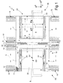
- Figures 1 to 3 illustrate a gyroscope 1 according to a first embodiment of the invention.
- the gyroscope 1 comprises an acceleration sensor 23 formed by two parts 2a, 2b, which are symmetrical with respect to a central axis of symmetry designated by A and connected together by two central springs 3, configured to be symmetrical with respect to a horizontal centroidal axis designated by B.
- each part 2a, 2b has a vertical centroidal axis designated by C.
- the axes A and C are parallel to the axis Y, while the axis B is parallel to the axis X.
- the intersection between the horizontal centroidal axis B and the vertical centroidal axis C constitutes the centroid G1 of each part 2a, 2b.
- the acceleration sensor 23 is sensitive to an angular velocity directed parallel to the axis Y.
- Each part 2a, 2b comprises a driving element 5 of concave shape, here a square C shape, and a sensitive mass 6, completely housed inside the space delimited by the driving element 5 but having a peripheral portion not facing the driving element 5 itself. Both the driving element 5 and the sensitive mass 6 are perforated as shown only in part in Figure 2.
- Each driving element 5 is formed by a first and a second oscillating arms 7, 8, which are parallel to one another and are connected at one end by a central cross member 9 extending perpendicular to the oscillating arms 7, 8.
- the two cross members 9 of the parts 2a, 2b extend parallel to one another, face one another, and are connected by the central springs 3.
- the first oscillating arms 7 are aligned together, as also are the second oscillating arms 8.
- Anchoring springs 10 extend from each end of the oscillating arms 7, 8 towards the outside of the respective driving elements 5.
- the anchoring spring 10, which can be seen more clearly in the detail of Figure 2, are of a folded type, i.e., they comprise at least two non-aligned portions, one connected to the respective driving element 5 and one having an anchoring end 11 fixed to a fixed substrate (as described in greater detail hereinafter with reference to Figure 3).
- the anchoring springs 10 are equal and are arranged in pairs symmetrically with respect to the centroidal vertical axis C and the centroidal horizontal axis B, so that the anchoring springs 10 are at equal distances from one another and balanced with respect to the centroid G1 of the respective part 2a, 2b of the gyroscope.
- the anchoring springs 10 are here made up of four portions extending orthogonally to the arms 7, 8 and connected, in pairs, via short connection portions at their ends.
- Elongated expansions hereinafter referred to as movable driving arms 12, extend towards the outside of the oscillating arms 7, 8, orthogonally to the arms, between pairs of anchoring springs 10, symmetrically with respect to both the centroidal horizontal axis B and the centroidal vertical axis C.
- Each movable driving arm 12 carries a plurality of movable driving electrodes 13, extending orthogonally from either side of the respective movable driving arms 12.
- each movable driving arm 12 Associated to each movable driving arm 12 is a first and a second fixed driving arms 14a, 14b (see Figure 2), which are parallel to the movable driving arms 12 and carry respective fixed driving electrodes 15a, 15b.
- the fixed driving electrodes 15a, 15b extend perpendicular to the fixed driving arms 14a, 14b towards the respective movable driving arms 12 and are comb-fingered to the movable driving electrodes 13.
- the first fixed driving arms 14a are arranged all on a same side of the respective movable driving arms 12 (in the example, on the right) and are all biased at a same first potential.
- the second fixed driving arms 14b are all arranged on the other side of the respective movable driving arms 12 (in the example, on the left) and are all biased at a same second potential.
- the driving element 5, the movable driving arms 12, the movable driving electrodes 13, the fixed driving arms 14a, 14b, and the fixed driving electrodes 15a, 15b together form a driving system 16 for each part 2a, 2b.
- the sensitive mass 6 has a basically plane shape, with the main extension in the direction of the axes X and Y.
- each sensitive mass 6 is rectangular in shape, with the length 11 in the Y direction, the width 12 in the X direction, and with a centroid G2, and is surrounded on three sides by the respective driving element 5.
- the coupling springs 24 extend mainly parallel to the oscillating arms 7, 8 and are configured so as to connect rigidly the sensitive mass 6 to the driving element 5 in a direction parallel to the axis X, to enable a limited movement of the sensitive mass 6 in the event of application of a force in the direction parallel to the axis Y, as explained hereinafter, and to enable its displacement in a direction parallel to the axis Z under the action of the apparent force due to Coriolis acceleration.
- each sensitive mass 6 there extends a sensing electrode 20 of deposited doped polycrystalline silicon (for example, polysilicon deposited by low-pressure chemical vapor deposition LPCVD), the perimeter of the sensing electrode 20 being represented by a dashed line in Figure 1.
- a sensing electrode 20 of deposited doped polycrystalline silicon for example, polysilicon deposited by low-pressure chemical vapor deposition LPCVD
- the perimeter of the sensing electrode 20 being represented by a dashed line in Figure 1.
- each sensitive mass 6 is separated from the respective sensing electrode 20 by an air gap 35 obtained by removal of a sacrificial material, such as deposited oxide.
- the sensitive mass 6 and the sensing electrode 20 thus form the plates of a capacitor 22 (represented by dashed lines in Figure 3), the dielectric whereof is formed by the air gap 35.
- Each sensing electrode 20, of rectangular shape has a length L1 in the Y direction that is greater than the length 11, and a width L2 in the X direction that is smaller than the length 12 of the respective sensitive mass 6.
- the length L1 of the sensing electrode 20 exceeds the length 11 of the sensitive mass 6 by an amount such that any displacement in the direction Y of the sensitive mass 6 (due to forces acting in that direction) will not reduce the facing area between the sensitive mass 6 and the sensing electrode 20.
- the width L2 of the sensing electrode 20 is smaller than the width 12 of the sensitive mass 6 by an amount such that any displacement of the latter in the direction X (due to the driving system 16 and/or to other forces acting in that direction) will not reduce the facing area between the sensitive mass 6 and the sensing electrode 20.
- capacitive coupling between the sensitive mass 6 and the sensing electrode 20 does not change following upon movements in the directions X and Y; instead, it does change for movements along the axis Z, as described below.
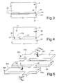
- Figure 3 shows a cross-section through the gyroscope 1.
- the sensitive mass 6 (as also the driving element 5, the springs 10, 24, the movable driving arms 12, and the fixed driving arms 14a, 14b) is formed in a structural layer, here constituted by an epitaxial layer 29 formed on top of a substrate 30 of monocrystalline silicon.
- the sensing electrode 20 is formed on top of an insulating layer 31, for example, a deposited oxide layer, which is, in turn, formed on top of the substrate 30.
- Figure 4 shows the cross-section of the gyroscope 1 at one anchoring end 11 of an anchoring spring 10.
- the anchoring end 11 has, at the bottom, a reduced portion 11a overlying, and in direct electrical contact with, a first connection region 33 of conductive material, formed in the layer of polycrystalline silicon of the sensing electrode 20 and indicated by a dashed line in Figure 1.
- the first connection region 33 enables biasing of the anchoring spring 10 and, more in general, of the driving element 5 and of the sensitive mass 6 at the desired potential.
- Figure 4 also shows the non-removed portions 32 of a sacrificial layer, which, where removed, forms the air gap 35.
- the insulating layer 31 and the sacrificial layer 32 extend only underneath the anchoring end 11, and have been removed underneath the movable parts (here the anchoring spring 10). Similar solutions of connection are used for the fixed driving elements 14a, 14b, where, however, the sacrificial area 22 is not generally removed.
- the gyroscope 1 is able to detect the magnitude of the angular velocity which causes a rotation of the gyroscope about the axis Y and hence in the plane of the sensitive mass 6.
- the Coriolis force is directed along the axis Z and causes a displacement of the sensitive mass 6 in the same direction.
- a special processing circuit (not shown) is able to detect the variation in capacitance and to find the magnitude of the angular velocity.
- the gyroscope 1 has a high sensitivity thanks to the large facing area between the sensitive mass 6 and the sensing electrode 20 and supplies an output of a single-ended type.
- Figure 5 illustrates an embodiment of a gyroscope 40, which supplies a differential reading of the angular velocity.
- the gyroscope 40 of Figure 5 still comprises a driving system 16 of the type described with reference to Figure 1, but each driving element 5 is here E-shaped and is provided with two concavities 41a, 41b facing outwards.
- each driving element 5 comprises, in addition to the oscillating arms 7, 8 and the central cross member 9, an intermediate arm 45, extending parallel to the axis X.
- Each driving element 5 is also here supported and biased through an anchoring spring 10 of a folded type, the springs having an anchoring end 11 and being arranged symmetrically with respect to the vertical centroidal axis C.
- a sensitive mass 42a, 42b is arranged inside each concavity 41a, 41b, has a generally rectangular shape and is supported in an eccentric way.
- each sensitive mass 42a, 42b is formed by a first smaller rectangular portion 43a and a second larger rectangular portion 43b, these portions being interconnected by a narrow portion 44.
- Each sensitive mass 42a, 42b has an own centroid G3.
- the sensitive mass 42a is supported by two supporting arms 46a extending parallel to the cross member 9 from the narrow portion 44 towards the oscillating arm 7 and towards the intermediate arm 45.
- the sensitive mass 42b is supported by two supporting arms 46b extending parallel to the cross member 9 from the narrow portion 44 towards the oscillating arm 8 and towards the intermediate arm 45.
- the supporting arms 46a and 46b form torsion springs.
- each sensitive mass 42a The supporting arms 46a of each sensitive mass 42a are aligned together, as are the oscillating arms 46b of each sensitive mass 42b, but, in each part 2a, 2b, the supporting arms 46a of the sensitive mass 42a are misaligned with respect to the supporting arms 46b of the sensitive mass 42b. All of the supporting arms 46a, 46b extend at a distance from the centroid G3 of the respective sensitive mass 42a, 42b. Also here the suspended masses 42a, 42b of the two parts 2a, 2b of the gyroscope 40 are arranged symmetrically with respect to the central axis of symmetry A.
- Respective sensing electrodes 48a, 48b extend underneath each portion 43a, 43b of the four suspended masses 42a, 42b.
- the sensing electrodes 48a face the smaller portions 43a
- the sensing electrodes 48b face the larger portions 43b.
- the sensing electrodes 48a, 48b are formed by a polycrystalline silicon layer, separated from the respective portion 43a, 43b by an air gap, and are connected to a processing circuit (not shown).
- the Coriolis force F acting on the centroid G3 of each sensitive mass 42a, 42b determines opposite rotations of the suspended masses 42a, 42b connected to a same driving element 5, since they have the centroid G 3 on opposite sides with respect to the respective supporting elements 46a, 46b.
- This rotation determines an opposite variation in the capacitance of the capacitors formed by each portion 43a, 43b of the suspended masses 42a, 42b and the respective sensing electrode 46a, 46b.
- the gyroscope 40 illustrated in Figure 5 is less sensitive than the gyroscope 1 of Figure 1, since the variation in capacitance due to rotation of the suspended masses 42a, 42b is less than the variation that may be obtained as a result of translation in the direction Z of the suspended masses 6, given the same external force F.
- the gyroscope 40 is, however, less subject to electrostatic pull-in due to mechanical shocks.
- the driving elements 5 and the sensing electrodes 20 it may happen that, following upon a mechanical shock, the driving elements 5 adhere to, and remain attracted by, the respective sensing electrodes 20, this being facilitated by the large facing area.
- a possible mechanical shock such as might cause rotation of the suspended masses 42a, 42b, does not in general cause a condition of "sticking", given that in this case each sensitive mass 42a, 42b touches the respective sensing electrode 48a, 48b only along one edge instead of with the entire surface.
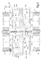
- Figure 7 presents an embodiment of the gyroscope 50 with double sensitive axis.
- the gyroscope 50 has a first sensitive axis extending in the plane of the sensitive mass 6, parallel to the axis Y, as in the embodiment of Figure 1, and a second sensitive axis extending in a direction perpendicular to the plane of the sensitive mass 6 and parallel to the axis Z.
- the gyroscope 50 has a basic structure similar to that of the gyroscope 1 of Figure 1, except for the fact that, in each part 2a, 2b, movable sensing electrodes 18 extend from the side of the sensitive mass 6 facing outwards, parallel to the oscillating arms 7, 8.
- the movable sensing electrodes 18 are comb-fingered to the fixed sensing electrodes 19a, 19b.
- each movable sensing electrode 18 is arranged between a fixed sensing electrode 19a and a fixed sensing electrode 19b.
- the fixed sensing electrodes 19a are all arranged on a first side of the movable sensing electrodes 18 and are electrically connected together at their outer ends through a first anchoring region 51.
- the fixed sensing electrodes 19b are all arranged on a second side of the movable sensing electrodes 18 and are electrically connected together through respective second anchoring regions 51 formed at their outer ends and connected together through a second connection region 55, represented by a dashed line in Figure 7 and illustrated in Figure 8.
- the fixed sensing electrodes 19a, 19b form, with the movable sensing electrodes 18, capacitors, the capacitance of which depends upon the distance between them, in a known way. Consequently, any displacement in the direction Y of the sensitive mass 6 causes a variation of opposite sign in the voltages of the fixed sensing electrodes 19a and 19b, which is detected and processed by an appropriate circuit (not shown) in a known way.
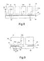
- Figure 8 is a cross-sectional view through the gyroscope at the second anchoring region 21 of the fixed sensing electrodes 19b.
- the second anchoring regions 21, which are formed in the same structural layer as the anchoring springs 10, i.e., the epitaxial layer 29, have at the bottom a reduced portion 21a formed by the epitaxial layer 29 itself, which overlies and is in direct electrical contact with the second connection region 55 formed in the same layer as the sensing electrodes 20.
- the second connection region 55 is formed on top of the insulating layer 31 and underneath the sacrificial layer 32, of which only some portions are visible, which have remained after the movable parts of the gyroscope 50 have been freed.
- the cross-section of Figure 8 also shows the fixed sensing electrodes 19a and, in a plane set back with respect to the plane of the cross section, the movable sensing electrodes 18, drawn with a dashed line.
- Figure 9 is a cross-section through the gyroscope 50 taken along a fixed sensing electrode 19a.
- the first anchoring region 51 is formed in the epitaxial layer 29 and has, at the bottom, a reduced portion 51a formed by the epitaxial layer 29, which overlies and is in direct electrical contact with a third connection region 37 of conductive material, formed in the same layer as the sensing electrodes 20 and the second (polysilicon) connection region 55, on top of the insulating layer 31 and underneath the sacrificial layer 32.
- the gyroscope 50 of Figures 7 to 9 is able to detect forces acting in the direction Z (sensitive axis parallel to the axis Y) as has been described with reference to Figure 1.
- the gyroscope is able to detect forces acting in the direction of the axis Y (sensitive axis parallel to the axis Z), in so far as any displacement in the direction Y is detected as a variation in capacitance between the movable sensing electrodes 18 and the fixed sensing electrodes 19a, 19b.
- the gyroscope 50 it is possible to distinguish the effects of forces or of components thereof acting in the three directions.
- the displacements in the direction X are not detected by the sensing electrodes 20, as mentioned with reference to Figure 1, and cause a same capacitive variation on the fixed sensing electrodes 19a and 19b and can thus be rejected.
- the displacements along the axis Y are not detected by the sensing electrodes 20, as mentioned previously with reference to the embodiment of Figure 1, but are detected by the fixed electrodes 19a and 19b, as explained above.
- the displacements along the axis Z are detected by the sensing electrode 20, as mentioned previously with reference to Figures 1-3. Their effect on the fixed sensing electrodes 19a and 19b can, instead, be rejected since they detect a same capacitive variation with respect to the movable sensing electrodes 18, as for the displacements in the direction X.
- the advantages of the described gyroscope are the following. First, it is possible to have, on a single plane, the sensitive elements that are able to detect forces acting along three cartesian axes, this enabling a reduction in the overall dimensions of a three-axes gyroscope.
- the advantage is all the greater in case of the third embodiment, where a single sensor 23 is able to measure forces acting in two perpendicular directions, and hence only two sensors are necessary for a three dimension measure.
- the compactness of the sensors and the reduction in their number further enable reduction in costs for manufacturing the gyroscope.
- Each sensor 23 and each sensing set is moreover sensitive only to the forces acting in the respective directions, and rejects actions in a perpendicular direction.
- the sensing precision may be increased even further by designing the thicknesses of the various layers so as to assign different degrees of sensitivity in the different directions, in particular, in the third embodiment.
- the first and the third embodiments have high sensitivity and hence are particularly suited in the case of low angular velocities; instead, the second embodiment, as mentioned previously, enables use of a simpler circuitry and makes it possible to avoid the risk of electrostatic pull-in.
Landscapes
- Physics & Mathematics (AREA)
- Engineering & Computer Science (AREA)
- General Physics & Mathematics (AREA)
- Radar, Positioning & Navigation (AREA)
- Remote Sensing (AREA)
- Gyroscopes (AREA)
Abstract
Description
- Figure 1 is a top plan view through the first embodiment, with single sensitive axis;
- Figure 2 illustrates a portion of the gyroscope of Figure 1, at an enlarged scale;
- Figure 3 is a cross-section taken along line III-III of Figure 1;
- Figure 4 is a cross-section taken along the line IV-IV of Figure 2;
- Figure 5 is a top plan view through a second embodiment of the invention, with single sensitive axis;
- Figure 6 is a schematic illustration in perspective view of a detail of Figure 5;
- Figure 7 is a top plan view through a third embodiment of the invention, with double sensitive axis;
- Figure 8 is a cross-section taken along the line VIII-VIII of Figure 7; and
- Figure 9 is a cross-section taken along the line IX-IX of Figure 7.
Claims (17)
- An integrated gyroscope (1; 40; 50), including an acceleration sensor (23) comprising:characterized in that said acceleration sensor (23) has a rotation axis (A) parallel to said second direction (Y), and said sensitive mass (6; 42a, 42b) is sensitive to forces acting in a third direction (Z) perpendicular to said first and second directions.a driving assembly (16);at least one sensitive mass (6; 42a, 42b) extending in at least one first direction (X) and at least one second direction (Y), said sensitive mass being moved by said driving assembly 16 in said first direction (X);a capacitive sensing electrode (20; 48a, 48b), facing said sensitive mass;
- The gyroscope according to claim 1, wherein said capacitive sensing electrode (20; 48a, 48b) comprises at least one conductive material region extending underneath and at a distance, in said third direction, from said sensitive mass (6; 42a, 42b).
- The gyroscope according to claim 2, wherein said driving assembly (16) comprises a driving element (5) connected to said sensitive mass (6; 42a, 42b) through a mechanical linkage (24; 46a, 46b), which enables, at least to one part of said sensitive mass, a movement having a component in said third direction (Z).
- The gyroscope according to claim 3, wherein said sensitive mass (6) can be translated parallel to said third direction (Z)
- The gyroscope according to claim 4, wherein said sensitive mass (6) and said capacitive sensing electrode (20) have a reciprocal facing area that is constant in presence of movements of said sensitive mass in said first direction (X) and/or in said second direction (Y).
- The gyroscope according to claim 4 or 5, wherein said driving element (5) surrounds, at least partially, said sensitive mass (6), said sensitive mass (6) and said capacitive sensing electrode (20) having a rectangular shape, a first one (6) between said sensitive mass and said capacitive sensing electrode having a length (12) in said first direction (X) greater than another one (20) between said sensitive mass and said capacitive sensing electrode, and a second one (20) between said sensitive mass and said capacitive sensing electrode having a length (L1) in said second direction (Y) greater than another one (6) between said sensitive mass and said capacitive sensing electrode.
- The gyroscope according to any one of claims 3 to 6, wherein said driving element (5) has an open concave shape partially surrounding said sensitive mass (6), and said sensitive mass (6) has a peripheral portion not facing said driving element.
- The gyroscope according to claim 7, further comprising movable sensing electrodes (18) extending from said peripheral portion of said sensitive mass (6) in said first direction (X), said movable sensing electrodes being comb-fingered to fixed sensing electrodes (19a, 19b) for detecting movements of said sensitive mass (6) in said second direction (Y).
- The gyroscope according to claim 3 or 4, wherein said at least one sensitive mass (42a) can turn about an eccentric axis (46a) parallel to said second direction (Y).
- The gyroscope according to claim 9, wherein said driving element (5) surrounds at least partially said sensitive mass (42a), said at least one sensitive mass (42a) has a first centroid (G3), and said mechanical linkage comprises a first pair of supporting arms (46a) aligned to one another and defining said eccentric axis, said supporting arms (46a) of said first pair extending between said driving element (5) and said at least one sensitive mass (42a), eccentrically with respect to said first centroid.
- The gyroscope according to claim 10, wherein said driving element (5) is E-shaped and comprises a first and a second oscillating arms (7, 8) and an intermediate arm (45) extending parallel to said first direction (X), said at least one sensitive mass (42a) extending between said first oscillating arm (7) and said intermediate arm (45), a second sensitive mass (42b) extending between said second oscillating arm (8) and said intermediate arm (45), having a second centroid (G3) and being supported by a second pair of supporting arms (46b), said supporting arms (46b) of said second pair extending eccentrically with respect to said second centroid.
- The gyroscope according to claim 11, wherein said supporting arms (46b) of said second pair are misaligned with respect to said supporting arms (46a) of said first pair.
- The gyroscope according to claim 11 or claim 12, wherein said at least one sensitive mass (42a) and said second sensitive mass (42b) have a generally rectangular shape and comprise a first portion (43a) that is smaller and a second portion (43b) that is larger, arranged on opposite sides with respect to the respective supporting arms (46a, 46b), and wherein a differential sensing electrode (48a, 48b) faces a respective one of said first and second portions of said at least one sensitive mass (42a) and said second sensitive mass (42b).
- The gyroscope according to any one of the preceding claims, wherein said driving element (5) and said sensitive mass (6; 42a, 42b) are formed in a same structural layer (29).
- The gyroscope according to claim 14, wherein said driving element (5) and said sensitive mass (6; 42a, 42b) extend on top of a conductive material body (30) and are spaced therefrom by an air gap (35), and said capacitive sensing electrode (20; 48a, 48b) is formed by a semiconductor material region extending on top of said conductive material body (30) and insulated therefrom, said semiconductor material region extending beneath said air gap.
- The gyroscope according to any of claims 3 to 15, wherein said driving assembly (16) further comprises a plurality of movable driving electrodes (13) extending from said driving element (5) and comb-fingered to a plurality of fixed driving electrodes (15a, 15b).
- The gyroscope according to any one of the preceding claims, comprising two symmetrical parts (2a, 2b) connected by central springs (3) and each including an own driving assembly (16), an own sensitive mass (6; 42a, 42b), and an own capacitive sensing electrode (20; 48a, 48b).
Priority Applications (3)
| Application Number | Priority Date | Filing Date | Title |
|---|---|---|---|
| EP20020425320 EP1365211B1 (en) | 2002-05-21 | 2002-05-21 | Integrated gyroscope of semiconductor material with at least one sensitive axis in the sensor plane |
| DE2002621103 DE60221103T2 (en) | 2002-05-21 | 2002-05-21 | Integrated gyroscope made of semiconductor material with at least one sensitive axis in the sensor plane |
| US10/443,647 US6928872B2 (en) | 2001-04-27 | 2003-05-21 | Integrated gyroscope of semiconductor material with at least one sensitive axis in the sensor plane |
Applications Claiming Priority (1)
| Application Number | Priority Date | Filing Date | Title |
|---|---|---|---|
| EP20020425320 EP1365211B1 (en) | 2002-05-21 | 2002-05-21 | Integrated gyroscope of semiconductor material with at least one sensitive axis in the sensor plane |
Publications (2)
| Publication Number | Publication Date |
|---|---|
| EP1365211A1 true EP1365211A1 (en) | 2003-11-26 |
| EP1365211B1 EP1365211B1 (en) | 2007-07-11 |
Family
ID=29286264
Family Applications (1)
| Application Number | Title | Priority Date | Filing Date |
|---|---|---|---|
| EP20020425320 Expired - Lifetime EP1365211B1 (en) | 2001-04-27 | 2002-05-21 | Integrated gyroscope of semiconductor material with at least one sensitive axis in the sensor plane |
Country Status (2)
| Country | Link |
|---|---|
| EP (1) | EP1365211B1 (en) |
| DE (1) | DE60221103T2 (en) |
Cited By (9)
| Publication number | Priority date | Publication date | Assignee | Title |
|---|---|---|---|---|
| WO2007104742A1 (en) * | 2006-03-10 | 2007-09-20 | Continental Teves Ag & Co. Ohg | Rate-of-rotation sensor having a coupling bar |
| WO2008015044A1 (en) | 2006-07-31 | 2008-02-07 | Robert Bosch Gmbh | Rotation-rate sensor |
| EP1933316A2 (en) | 2006-12-05 | 2008-06-18 | STMicroelectronics S.r.l. | Device and method for protecting an electronic appliance in critical motion conditions, in particular in case of fall |
| WO2009077263A1 (en) * | 2007-12-18 | 2009-06-25 | Robert Bosch Gmbh | Yaw rate sensor and method for operating a yaw rate sensor |
| US7694563B2 (en) | 2006-03-10 | 2010-04-13 | Stmicroelectronics S.R.L. | Microelectromechanical integrated sensor structure with rotary driving motion |
| US7924267B2 (en) | 2004-12-29 | 2011-04-12 | Stmicroelectronics S.R.L. | Pointing device for a computer system with automatic detection of lifting, and relative control method |
| US8683863B2 (en) | 2010-01-12 | 2014-04-01 | Robert Bosch Gmbh | Micromechanical yaw rate sensor having two sensitive axes and coupled detection modes |
| USRE45792E1 (en) | 2007-09-11 | 2015-11-03 | Stmicroelectronics S.R.L. | High sensitivity microelectromechanical sensor with driving motion |
| CN115389781A (en) * | 2022-07-29 | 2022-11-25 | 瑞声开泰科技(武汉)有限公司 | Accelerometer |
Families Citing this family (1)
| Publication number | Priority date | Publication date | Assignee | Title |
|---|---|---|---|---|
| ITTO20040848A1 (en) | 2004-12-01 | 2005-03-01 | St Microelectronics Srl | MANUAL DEVICE FOR AIMING A CALCULATOR SYSTEM WITH INERTIAL EVENT-CLICK DETECTION AND RELATIVE EVENT-CLICK METHOD OF DETECTION |
Citations (3)
| Publication number | Priority date | Publication date | Assignee | Title |
|---|---|---|---|---|
| US5747690A (en) * | 1995-12-27 | 1998-05-05 | Samsung Electronics Co., Ltd. | Vibratory microgyroscope |
| EP1098170A2 (en) * | 1999-11-04 | 2001-05-09 | Samsung Electronics Co., Ltd. | Microgyroscope with two resonant plates |
| US6349597B1 (en) * | 1996-10-07 | 2002-02-26 | Hahn-Schickard-Gesellschaft Fur Angewandte Forschung E.V. | Rotation rate sensor with uncoupled mutually perpendicular primary and secondary oscillations |
-
2002
- 2002-05-21 EP EP20020425320 patent/EP1365211B1/en not_active Expired - Lifetime
- 2002-05-21 DE DE2002621103 patent/DE60221103T2/en not_active Expired - Lifetime
Patent Citations (3)
| Publication number | Priority date | Publication date | Assignee | Title |
|---|---|---|---|---|
| US5747690A (en) * | 1995-12-27 | 1998-05-05 | Samsung Electronics Co., Ltd. | Vibratory microgyroscope |
| US6349597B1 (en) * | 1996-10-07 | 2002-02-26 | Hahn-Schickard-Gesellschaft Fur Angewandte Forschung E.V. | Rotation rate sensor with uncoupled mutually perpendicular primary and secondary oscillations |
| EP1098170A2 (en) * | 1999-11-04 | 2001-05-09 | Samsung Electronics Co., Ltd. | Microgyroscope with two resonant plates |
Cited By (17)
| Publication number | Priority date | Publication date | Assignee | Title |
|---|---|---|---|---|
| US7924267B2 (en) | 2004-12-29 | 2011-04-12 | Stmicroelectronics S.R.L. | Pointing device for a computer system with automatic detection of lifting, and relative control method |
| US7694563B2 (en) | 2006-03-10 | 2010-04-13 | Stmicroelectronics S.R.L. | Microelectromechanical integrated sensor structure with rotary driving motion |
| CN101443629B (en) * | 2006-03-10 | 2015-12-02 | 大陆-特韦斯贸易合伙股份公司及两合公司 | There is the speed probe of articulated beam |
| US8261614B2 (en) | 2006-03-10 | 2012-09-11 | Continental Teves Ag & Co. Ohg | Rotational speed sensor having a coupling bar |
| WO2007104742A1 (en) * | 2006-03-10 | 2007-09-20 | Continental Teves Ag & Co. Ohg | Rate-of-rotation sensor having a coupling bar |
| JP2010501829A (en) * | 2006-07-31 | 2010-01-21 | ローベルト ボツシユ ゲゼルシヤフト ミツト ベシユレンクテル ハフツング | Rotation rate sensor |
| WO2008015044A1 (en) | 2006-07-31 | 2008-02-07 | Robert Bosch Gmbh | Rotation-rate sensor |
| US9261363B2 (en) | 2006-07-31 | 2016-02-16 | Robert Bosch Gmbh | Yaw rate sensor |
| US7782219B2 (en) | 2006-12-05 | 2010-08-24 | Stmicroelectronics S.R.1. | Device and method for protecting an electronic appliance in critical motion conditions, in particular in case of fall |
| EP1933316A2 (en) | 2006-12-05 | 2008-06-18 | STMicroelectronics S.r.l. | Device and method for protecting an electronic appliance in critical motion conditions, in particular in case of fall |
| USRE45792E1 (en) | 2007-09-11 | 2015-11-03 | Stmicroelectronics S.R.L. | High sensitivity microelectromechanical sensor with driving motion |
| USRE45855E1 (en) | 2007-09-11 | 2016-01-19 | Stmicroelectronics S.R.L. | Microelectromechanical sensor with improved mechanical decoupling of sensing and driving modes |
| WO2009077263A1 (en) * | 2007-12-18 | 2009-06-25 | Robert Bosch Gmbh | Yaw rate sensor and method for operating a yaw rate sensor |
| CN101903740B (en) * | 2007-12-18 | 2013-03-27 | 罗伯特·博世有限公司 | Yaw rate sensor and method for operating a yaw rate sensor |
| US8443666B2 (en) | 2007-12-18 | 2013-05-21 | Robert Bosch Gmbh | Rate-of-rotation sensor and method for operating a rate-of-rotation sensor |
| US8683863B2 (en) | 2010-01-12 | 2014-04-01 | Robert Bosch Gmbh | Micromechanical yaw rate sensor having two sensitive axes and coupled detection modes |
| CN115389781A (en) * | 2022-07-29 | 2022-11-25 | 瑞声开泰科技(武汉)有限公司 | Accelerometer |
Also Published As
| Publication number | Publication date |
|---|---|
| EP1365211B1 (en) | 2007-07-11 |
| DE60221103D1 (en) | 2007-08-23 |
| DE60221103T2 (en) | 2008-04-03 |
Similar Documents
| Publication | Publication Date | Title |
|---|---|---|
| US6928872B2 (en) | Integrated gyroscope of semiconductor material with at least one sensitive axis in the sensor plane | |
| US7258011B2 (en) | Multiple axis accelerometer | |
| KR101301403B1 (en) | Micromechanical acceleration sensor | |
| JP3327595B2 (en) | 3-axis accelerometer | |
| US7748272B2 (en) | MEMS sensor suite on a chip | |
| CN100437118C (en) | Triaxial MEMS sensor with single test mass | |
| JP3941694B2 (en) | Acceleration sensor | |
| CN112485470B (en) | Low Noise Multi-Axis MEMS Accelerometer | |
| US7168317B2 (en) | Planar 3-axis inertial measurement unit | |
| EP2192383A1 (en) | Uniaxial or biaxial microelectromechanical gyroscope with improved sensitivity to angular velocity detection | |
| EP2431722A2 (en) | Mems sensor capable of sensing acceleration and pressure | |
| US20060169044A1 (en) | Mems accelerometers | |
| CN101568840B (en) | Micromachined multi-axis accelerometer | |
| CN107003333B (en) | MEMS sensor and semiconductor packages | |
| US20070034007A1 (en) | Multi-axis micromachined accelerometer | |
| JPWO2010055716A1 (en) | Acceleration sensor | |
| US9128114B2 (en) | Capacitive sensor device and a method of sensing accelerations | |
| US11977094B2 (en) | Seesaw accelerometer | |
| EP1365211B1 (en) | Integrated gyroscope of semiconductor material with at least one sensitive axis in the sensor plane | |
| US6122963A (en) | Electronic component for measuring acceleration | |
| US20190271717A1 (en) | Accelerometer sensor | |
| US20060156815A1 (en) | Solid-state gyroscopes and planar three-axis inertial measurement unit | |
| JP5292600B2 (en) | Acceleration sensor | |
| EP0753753B1 (en) | Impact sensor | |
| CN109073673A (en) | Micro mechanical sensor and method for manufacturing micro mechanical sensor |
Legal Events
| Date | Code | Title | Description |
|---|---|---|---|
| PUAI | Public reference made under article 153(3) epc to a published international application that has entered the european phase |
Free format text: ORIGINAL CODE: 0009012 |
|
| AK | Designated contracting states |
Kind code of ref document: A1 Designated state(s): AT BE CH CY DE DK ES FI FR GB GR IE IT LI LU MC NL PT SE TR |
|
| AX | Request for extension of the european patent |
Extension state: AL LT LV MK RO SI |
|
| 17P | Request for examination filed |
Effective date: 20040521 |
|
| AKX | Designation fees paid |
Designated state(s): DE FR GB IT |
|
| 17Q | First examination report despatched |
Effective date: 20041021 |
|
| GRAP | Despatch of communication of intention to grant a patent |
Free format text: ORIGINAL CODE: EPIDOSNIGR1 |
|
| GRAS | Grant fee paid |
Free format text: ORIGINAL CODE: EPIDOSNIGR3 |
|
| GRAA | (expected) grant |
Free format text: ORIGINAL CODE: 0009210 |
|
| AK | Designated contracting states |
Kind code of ref document: B1 Designated state(s): DE FR GB IT |
|
| REG | Reference to a national code |
Ref country code: GB Ref legal event code: FG4D |
|
| REF | Corresponds to: |
Ref document number: 60221103 Country of ref document: DE Date of ref document: 20070823 Kind code of ref document: P |
|
| ET | Fr: translation filed | ||
| PLBE | No opposition filed within time limit |
Free format text: ORIGINAL CODE: 0009261 |
|
| STAA | Information on the status of an ep patent application or granted ep patent |
Free format text: STATUS: NO OPPOSITION FILED WITHIN TIME LIMIT |
|
| 26N | No opposition filed |
Effective date: 20080414 |
|
| REG | Reference to a national code |
Ref country code: FR Ref legal event code: ST Effective date: 20090119 |
|
| PG25 | Lapsed in a contracting state [announced via postgrant information from national office to epo] |
Ref country code: FR Free format text: LAPSE BECAUSE OF NON-PAYMENT OF DUE FEES Effective date: 20080602 |
|
| PG25 | Lapsed in a contracting state [announced via postgrant information from national office to epo] |
Ref country code: IT Free format text: LAPSE BECAUSE OF NON-PAYMENT OF DUE FEES Effective date: 20080521 |
|
| PGFP | Annual fee paid to national office [announced via postgrant information from national office to epo] |
Ref country code: DE Payment date: 20210421 Year of fee payment: 20 |
|
| PGFP | Annual fee paid to national office [announced via postgrant information from national office to epo] |
Ref country code: GB Payment date: 20210422 Year of fee payment: 20 |
|
| REG | Reference to a national code |
Ref country code: DE Ref legal event code: R071 Ref document number: 60221103 Country of ref document: DE |
|
| REG | Reference to a national code |
Ref country code: GB Ref legal event code: PE20 Expiry date: 20220520 |
|
| PG25 | Lapsed in a contracting state [announced via postgrant information from national office to epo] |
Ref country code: GB Free format text: LAPSE BECAUSE OF EXPIRATION OF PROTECTION Effective date: 20220520 |