EP1365196A2 - Wall-mounted type microwave oven - Google Patents
Wall-mounted type microwave oven Download PDFInfo
- Publication number
- EP1365196A2 EP1365196A2 EP02256243A EP02256243A EP1365196A2 EP 1365196 A2 EP1365196 A2 EP 1365196A2 EP 02256243 A EP02256243 A EP 02256243A EP 02256243 A EP02256243 A EP 02256243A EP 1365196 A2 EP1365196 A2 EP 1365196A2
- Authority
- EP
- European Patent Office
- Prior art keywords
- oven body
- slide duct
- exhaust gas
- slide
- exhaust fan
- Prior art date
- Legal status (The legal status is an assumption and is not a legal conclusion. Google has not performed a legal analysis and makes no representation as to the accuracy of the status listed.)
- Granted
Links
Images



Classifications
-
- F—MECHANICAL ENGINEERING; LIGHTING; HEATING; WEAPONS; BLASTING
- F24—HEATING; RANGES; VENTILATING
- F24C—DOMESTIC STOVES OR RANGES ; DETAILS OF DOMESTIC STOVES OR RANGES, OF GENERAL APPLICATION
- F24C15/00—Details
- F24C15/20—Removing cooking fumes
-
- H—ELECTRICITY
- H05—ELECTRIC TECHNIQUES NOT OTHERWISE PROVIDED FOR
- H05B—ELECTRIC HEATING; ELECTRIC LIGHT SOURCES NOT OTHERWISE PROVIDED FOR; CIRCUIT ARRANGEMENTS FOR ELECTRIC LIGHT SOURCES, IN GENERAL
- H05B6/00—Heating by electric, magnetic or electromagnetic fields
- H05B6/64—Heating using microwaves
- H05B6/6426—Aspects relating to the exterior of the microwave heating apparatus, e.g. metal casing, power cord
- H05B6/6429—Aspects relating to mounting assemblies of wall-mounted microwave ovens
-
- F—MECHANICAL ENGINEERING; LIGHTING; HEATING; WEAPONS; BLASTING
- F24—HEATING; RANGES; VENTILATING
- F24C—DOMESTIC STOVES OR RANGES ; DETAILS OF DOMESTIC STOVES OR RANGES, OF GENERAL APPLICATION
- F24C15/00—Details
- F24C15/20—Removing cooking fumes
- F24C15/2042—Devices for removing cooking fumes structurally associated with a cooking range e.g. downdraft
-
- H—ELECTRICITY
- H05—ELECTRIC TECHNIQUES NOT OTHERWISE PROVIDED FOR
- H05B—ELECTRIC HEATING; ELECTRIC LIGHT SOURCES NOT OTHERWISE PROVIDED FOR; CIRCUIT ARRANGEMENTS FOR ELECTRIC LIGHT SOURCES, IN GENERAL
- H05B6/00—Heating by electric, magnetic or electromagnetic fields
- H05B6/64—Heating using microwaves
- H05B6/642—Cooling of the microwave components and related air circulation systems
- H05B6/6423—Cooling of the microwave components and related air circulation systems wherein the microwave oven air circulation system is also used as air extracting hood
Definitions
- the present invention relates in general to a wall-mounted type cooking apparatus such as a microwave oven, and more particularly, to a wall-mounted type microwave oven arranged to exhaust gas and odors of food generated from an oven range positioned below the wall-mounted type microwave oven.
- Figure 1 shows a conventional wall-mounted type microwave oven 1 installed over an oven range 2.
- the wall-mounted type microwave oven 1 is installed over the oven range 2 and exhausts gas, fumes and odors of food generated from the oven range 2 to the outside.
- the wall-mounted type microwave oven 1 also serves as a cooking apparatus which cooks food therein using high-frequency electromagnetic waves.
- the oven range 2 is provided at its top with a plurality of top burners 3 to cook food, for example, by combustion of gas.
- the wall-mounted type microwave oven 1 is adapted to cook food in a cooking chamber (not shown) by an intermolecular frictional heat which is generated by repeatedly agitating water molecules of the food with high-frequency electromagnetic wave energy generated from a magnetron (not shown).
- FIG. 2 schematically shows an internal configuration of the conventional wall-mounted type microwave oven 1.
- the wall-mounted type microwave oven 1 includes an exhaust path 13 to exhaust gas and odors generated from food to the outside, and a cooking chamber 11 and an electrical component compartment 12 which are isolated from each other in an oven body 10.
- the cooking chamber 11 and the electrical component compartment 12 are provided at their bottoms, sides and tops with the exhaust path 13 to exhaust the gas and fumes generated from the oven range 2 (see Figure 1) disposed below the wall-mounted type microwave oven 1.
- the oven body 10 is provided at an upper portion of its back with an exhaust fan 14 which sucks in the gas and fumes introduced into the exhaust path 13 and discharges them to the outside.
- the exhaust path 13 constitutes a flow path isolated from the cooking chamber 11 and the electrical component compartment 12.
- the electrical component compartment 12 includes a cooling fan 15 which cools electrical components disposed in the electrical component compartment 12.
- the electrical component compartment 12 is further provided at an upper portion of its front face with a front air inlet 16, which allows outside air to be introduced into the electrical component compartment 12 therethrough by operation of the cooling fan 15.
- a partition plate 17 which is located between the cooking chamber 11 and the electrical component compartment 12 is formed with a plurality of vent holes 18, so as to introduce air sucked into the electrical component compartment 12 into the cooking chamber 11 therethrough to ventilate the cooking chamber 11.
- the cooking chamber 11 is formed with a plurality of vent holes 19 at its upper surface and on the side opposite to the partition plate 17 to allow the air in the cooking chamber 11 to be discharged to the outside therethrough.
- the cooking chamber 11 is also provided with a front air outlet 20 which allows the air passing through the vent holes 19 to be discharged to the outside therethrough.
- the conventional wall-mounted type microwave oven 1 cannot efficiently suck in the exhaust gas, fumes and odors generated from the oven range 2 disposed below the wall-mounted type microwave oven 1. More specifically, as shown in Figure 1, top burners 3 of the oven range 2 are arranged in two rows, i.e., a front row of top burners 3a and a rear row of top burners 3b. Yet, the conventional wall-mounted type microwave oven 1, which is disposed over the oven range 2, is sized to cover only the rear row of top burners 3b. Accordingly, the wall-mounted type microwave oven 1 cannot efficiently suck in the exhaust gas, fumes and odors generated from the front row of top burners 3a using the exhaust fan 14 of Figure 2. Hence, the exhaust gas, fumes and odors generated from the front row of top burners 3a cannot be sufficiently discharged to the outside, thereby causing room air to be contaminated.
- a wall-mounted type microwave oven comprising an oven body which defines an exterior appearance of the microwave oven, an intake port which is provided at a bottom panel of the oven body and allows exhaust gas to be introduced into the oven body therethrough, a main exhaust fan internally provided at an upper portion of the oven body, a main exhaust path which communicates with the intake port and the main exhaust fan, and a slide duct which is provided under the oven body, and retractably extends forward to guide the exhaust gas generated from an area positioned below the oven body.
- the slide duct may comprise a lower plate, side plates which are upwardly extended from corresponding sides of the lower plate, and a front plate which is upwardly extended from a front end of the lower plate so as to define an auxiliary exhaust path, which guides the exhaust gas toward the main exhaust path, between the bottom panel of the oven body and the lower plate of the slide duct.
- the slide duct may be further provided with an upper plate connected to upper ends of the side plates and the front plate, and the upper and lower plates may include a through port which communicates with the intake port of the bottom panel of the oven body where the slide duct is retracted into the oven body.
- the slide duct may further include an auxiliary exhaust fan which is provided at an internal front portion of the slide duct, and sucks in the exhaust gas generated from a region below the slide duct where the slide duct is extended forward, and guide plates which accommodate the auxiliary exhaust fan and extend toward the oven body to guide the exhaust gas introduced by the auxiliary exhaust fan toward the main exhaust path of the oven body.
- an auxiliary exhaust fan which is provided at an internal front portion of the slide duct, and sucks in the exhaust gas generated from a region below the slide duct where the slide duct is extended forward
- guide plates which accommodate the auxiliary exhaust fan and extend toward the oven body to guide the exhaust gas introduced by the auxiliary exhaust fan toward the main exhaust path of the oven body.
- the side plates of the slide duct may include corresponding rails which extend longitudinally along the side plates, and the oven body may include side panels having corresponding slide grooves, along which the rails of the slide duct are slidably moved back and forth.
- wall-mountable cooking apparatus comprising: an oven body which defines an outer appearance of the cooking apparatus; a cooking chamber to receive food therein; a heating unit which cooks the food; a main exhaust path provided in the oven body; an intake port which introduces exhaust gas below the oven body into the main exhaust path; a main exhaust fan which communicates with the main exhaust path and discharges the exhaust gas to a desired location; and a slide duct which retractably extends from the oven body and guides the exhaust gas below the slide duct toward the intake port.
- a wall-mountable cooking apparatus comprising: an oven body which defines an outer appearance of the cooking apparatus; a main exhaust port provided at a bottom panel of the oven body; a main exhaust fan which discharges exhaust gas introduced through the main exhaust port to a desired location; and a slide duct which retractably extends from the oven body and guides the exhaust gas below the slide duct toward the main exhaust port.
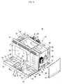
- Figure 3 shows a wall-mounted type microwave oven 50 according to an embodiment of the present invention, in which a slide duct 70 is extended forward therefrom.
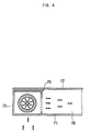
- Figure 4 shows a cross-sectional view taken along line IV-IV of Figure 3, and illustrates an exhaust path of the slide duct 70.
- the wall-mounted type microwave oven 50 includes a box-shaped oven body 51 having front and rear panels 52 and 53, side panels 54 and 55, and top and bottom panels 56 and 57.
- the oven body 51 includes a cooking chamber 58 to receive food therein, and an electrical component compartment 59 which is isolated from the cooking chamber 58 and outputs high-frequency electromagnetic waves to cook the food.
- the bottom plate 57 includes intake ports 61 which allow exhaust gas and odors generated from an oven range 2 (see Figure 6) to be introduced into the oven body 51 therethrough.
- the oven body 51 further includes a main exhaust fan 62 which is provided at an upper back portion thereof. The main exhaust fan 62 sucks in the exhaust gas and discharges it to the outside.
- An exhaust path 63 is disposed between the intake ports 61 and the main exhaust fan 62, and is adapted to guide the exhaust gas introduced through the intake ports 61 toward the main exhaust fan 62.
- the exhaust path 63 includes a space defined between the cooking chamber 58 and the electric component compartment 59, and both the side panels 54 and 55, the bottom panel 57 and the rear panel 53 of the oven body 51.
- the slide duct 70 comprises upper and lower plates 72 and 71 which are of a size approximately equal to a size of the bottom panel 57 of the oven body 51, side plates 73 and 74 connected between corresponding sides of the upper and lower plates 72 and 71, and a front plate 75 connected between front sides of the upper and lower plates 72 and 71.
- the upper and lower plates 72 and 71 of the slide duct 70 include corresponding through ports 77 which communicate with the intake ports 61 of the bottom panel 57 of the oven body 51, so as to allow the exhaust gas to be introduced into the intake ports 61 via the through ports 77 where the slide duct 70 is retracted into the oven body 51.
- the slide duct 70 further comprises an auxiliary exhaust fan unit 79 which is provided at an internal front portion thereof, and directs the exhaust gas to the main exhaust fan 62 where, for example, the slide duct 70 is extended forward.
- the auxiliary exhaust fan unit 79 is opened at its lower and side surfaces, and permits the exhaust gas to be introduced into the oven body 51 therethrough.
- the auxiliary exhaust fan unit 79 is designed to have a blowing capacity smaller than that of the main exhaust fan 62 so as to have the exhaust gas be sucked and directed toward the main exhaust fan 62.
- the exhaust gas can be directed to the oven body 51 by the auxiliary exhaust fan unit 79 without the upper plate 72.
- the slide duct 70 is provided therein with a pair of guide plates 78, which extend toward the oven body from both sides of the auxiliary exhaust fan unit 79 and guide the exhaust gas introduced by the auxiliary exhaust fan unit 79 toward the bottom plate 57 of the oven body 51. Since the slide duct 70 is provided therein with an auxiliary exhaust path 76 by the pair of guide plates 78, the exhaust gas introduced by the auxiliary exhaust fan unit 79 can be guided to the intake port 61 of the oven body 51 without passing through the through ports 77.
- the side plates 73 and 74 of the slide duct 70 are provided at their outer surfaces with rails 80, which extend longitudinally along the side plates 73 and 74, and the side panels 54 and 55 of the oven body 51 are provided at lower ends of their inner surfaces with corresponding slide grooves 81, in which the rails 80 of the side plates 73 and 74 are slidably inserted.
- the rails 80 are provided at their rear ends with corresponding stop pieces 82 which extend upward.
- the front panel 52 is provided at both sides of its lower end with stoppers 83 which extend downward, so as to prevent separation of the slide duct 70 from the oven body 51.
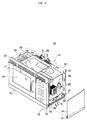
- Figure 6 shows the wall-mounted type microwave oven 50 according to the present invention, in which the slide duct 70 is slidably extended forward to efficiently suck exhaust gas generated from a front row of top burners 3a, or both front and rear rows of top burners 3a and 3b of an oven range 2 disposed below the wall-mounted type microwave oven 50.
- the slide duct 70 When it is not necessary to use the slide duct 70, because only the rear row of top burners 3b of the oven range 2 are operated, the slide duct 70 can be retracted into the oven body 51, as shown in Figure 5. At this point, by the operation of the main exhaust fan 62, exhaust gas and odors of food generated from the rear row of top burners 3b are introduced into the exhaust path 63 via the through ports 77 of the slide duct 70 and the intake ports 61 of the bottom panel 57 and discharged to the outside.
- the present invention provides a wall-mounted type microwave oven having a slide duct which slidably extends forward to efficiently exhaust gas generated from an oven range occupying a larger area than that of the wall-mounted type microwave oven. Accordingly, the exhaust gas is sufficiently discharged to the outside, and an odorless cooking environment is maintained.
Landscapes
- Engineering & Computer Science (AREA)
- Physics & Mathematics (AREA)
- Electromagnetism (AREA)
- Chemical & Material Sciences (AREA)
- Combustion & Propulsion (AREA)
- Mechanical Engineering (AREA)
- General Engineering & Computer Science (AREA)
- Electric Ovens (AREA)
- Baking, Grill, Roasting (AREA)
Abstract
Description
Claims (14)
- A wall-mounted type cooking apparatus, comprising:an oven body (51) which defines an exterior appearance of the cooking apparatus;an intake port (61) which is provided at a bottom panel (57) of the oven body (51), and allows exhaust gas to be introduced into the oven body therethrough;a main exhaust fan (62) internally provided at an upper portion of the oven body;a main exhaust path (63) which communicates with the intake port (61) and the main exhaust fan (62); anda slide duct (70) which is provided under the oven body, and retractably extends forward to guide exhaust gas generated from an area positioned below the oven body.
- The apparatus of claim 1, wherein the slide duct (70) comprises:a lower plate (71);side plates (73,74) upwardly extended from corresponding sides of the lower plate; anda front plate (75) upwardly extended from a front end of the lower plate so as to define an auxiliary exhaust path (76), which guides the exhaust gas toward the main exhaust path (63), between the bottom panel (57) of the oven body (51) and the lower plate (71) of the slide duct (70).
- The apparatus of claim 2, wherein the slide duct (70) further comprises an upper plate (72) connected to upper ends of the side plates (73,74) and the front plate (75).
- The apparatus of claim 2 or 3, wherein the upper and lower plates (71,72) include a through port (77) which communicates with the intake port (61) of the bottom panel (57) of the oven body (51) where the slide duct (70) is retracted into the oven body (51).
- The apparatus of any preceding claim, wherein the slide duct (70) further comprises an auxiliary exhaust fan (79) which is provided at an internal front portion of the slide duct, and sucks in the exhaust gas generated from a region below the slide duct where the slide duct is extended forward.
- The apparatus of claim 5, wherein the slide duct (70) further comprises guide plates (78) which accommodate the auxiliary exhaust fan (79) and extend toward the oven body (51) to guide the exhaust gas introduced by the auxiliary exhaust fan toward the main exhaust path (63) of the oven body.
- The apparatus of claim 2 or any claim dependent thereon, wherein:the side plates (73,74) of the slide duct include corresponding rails (80) which extend longitudinally along the side plates, and the oven body includes side panels having corresponding slide grooves (81), along which the rails of the slide duct are slidably moved back and forth.
- The apparatus of claim 7, wherein:the rails (80) include corresponding stop pieces (82) which are provided at rear ends of the rails and extend upward, and the oven body further includes a front panel having stoppers (83) which are provided at a lower end of the front panel, and extend downward to catch the corresponding stop pieces (82) of the rails.
- The apparatus of any preceding claim, wherein the slide duct (70) extends forward to guide the exhaust gas toward the intake port (61).
- The apparatus of any preceding claim, wherein:the slide duct (70) includes an auxiliary exhaust fan (79) which directs the exhaust gas generated from a region below the slide duct toward the intake port (61), and the main exhaust fan (63) and the auxiliary exhaust fan (79) operate concurrently in response to the slide duct (70) being extended forward.
- The apparatus of any preceding claim, wherein the slide duct (70) is provided below and beyond vertical sides (52) of the oven body (51).
- The apparatus of any preceding claim, wherein the slide duct (70) extends past the oven body (51) and forward of the oven body (51).
- The apparatus of any preceding claim, wherein the apparatus is a microwave oven.
- The apparatus of claim 13, comprising:a cooking chamber to contain food therein; anda magnetron which generates electromagnetic waves to cook the food.
Applications Claiming Priority (2)
| Application Number | Priority Date | Filing Date | Title |
|---|---|---|---|
| KR10-2002-0028760A KR100419207B1 (en) | 2002-05-23 | 2002-05-23 | Wall-Mounted Type Microwave Oven |
| KR2002028760 | 2002-05-23 |
Publications (3)
| Publication Number | Publication Date |
|---|---|
| EP1365196A2 true EP1365196A2 (en) | 2003-11-26 |
| EP1365196A3 EP1365196A3 (en) | 2006-10-25 |
| EP1365196B1 EP1365196B1 (en) | 2009-02-25 |
Family
ID=29398539
Family Applications (1)
| Application Number | Title | Priority Date | Filing Date |
|---|---|---|---|
| EP02256243A Expired - Lifetime EP1365196B1 (en) | 2002-05-23 | 2002-09-10 | Wall-mounted type microwave oven with built-in extractor hood |
Country Status (6)
| Country | Link |
|---|---|
| US (1) | US6797930B2 (en) |
| EP (1) | EP1365196B1 (en) |
| JP (1) | JP4160356B2 (en) |
| KR (1) | KR100419207B1 (en) |
| CN (1) | CN1203279C (en) |
| DE (1) | DE60231288D1 (en) |
Cited By (4)
| Publication number | Priority date | Publication date | Assignee | Title |
|---|---|---|---|---|
| EP1445546A1 (en) * | 2003-02-10 | 2004-08-11 | Samsung Electronics Co., Ltd. | Combination hood and microwave oven |
| CN100360853C (en) * | 2004-02-26 | 2008-01-09 | Lg电子株式会社 | Combined microwave oven and hood |
| CN107044677A (en) * | 2017-06-13 | 2017-08-15 | 袁静 | A kind of smoke exhaust ventilator being convenient to clean |
| EP3271657A4 (en) * | 2015-03-19 | 2018-11-14 | LG Electronics Inc. | Cooking device |
Families Citing this family (29)
| Publication number | Priority date | Publication date | Assignee | Title |
|---|---|---|---|---|
| US6894260B2 (en) * | 2001-12-04 | 2005-05-17 | Matsushita Electric Industrial Co., Ltd. | High frequency heating apparatus |
| KR100565222B1 (en) * | 2003-11-03 | 2006-03-30 | 엘지전자 주식회사 | Hood guide microwave exhaust guide |
| US20050150900A1 (en) * | 2004-01-09 | 2005-07-14 | American Trim, L.L.C. | Beverage can dispenser |
| US7708960B2 (en) * | 2006-03-31 | 2010-05-04 | Spx Corporation | Dry heat convection sterilization system |
| KR101291412B1 (en) * | 2006-12-27 | 2013-07-30 | 엘지전자 주식회사 | Microwave range having hood |
| KR101291426B1 (en) * | 2007-01-02 | 2013-07-30 | 엘지전자 주식회사 | Microwave range having hood |
| US7470877B2 (en) | 2007-03-08 | 2008-12-30 | Whirlpool Corporation | Microwave oven and ventilation hood combination system |
| KR101085499B1 (en) | 2007-04-25 | 2011-11-23 | 삼성전자주식회사 | Wall Mount Microwaves & Hoods |
| KR101450558B1 (en) | 2008-07-21 | 2014-10-21 | 엘지전자 주식회사 | ventilation hood |
| KR101453273B1 (en) * | 2008-08-13 | 2014-10-23 | 동부대우전자 주식회사 | Convection type microwave oven |
| KR101535304B1 (en) * | 2009-02-11 | 2015-07-08 | 엘지전자 주식회사 | Microwave oven combined with hood |
| KR101509767B1 (en) | 2009-02-11 | 2015-04-06 | 엘지전자 주식회사 | Microwave oven combined with hood |
| US9191999B2 (en) * | 2009-09-01 | 2015-11-17 | Manitowoc Foodservice Companies, Llc | Method and apparatus for venting a cooking device |
| CN102192538B (en) * | 2010-03-08 | 2015-05-20 | 乐金电子(天津)电器有限公司 | Embedded microwave oven with novel smoke pumping structure |
| US9175862B2 (en) * | 2011-10-11 | 2015-11-03 | Mikhail Chtchetinin | Built-in retractable ventilation hood assembly |
| KR101291505B1 (en) * | 2011-11-25 | 2013-08-01 | 엘지전자 주식회사 | Microwave oven having a hood |
| KR101496629B1 (en) * | 2012-03-16 | 2015-02-25 | 엘지전자 주식회사 | Microwave oven having a hood |
| US9226426B2 (en) * | 2012-07-18 | 2015-12-29 | International Business Machines Corporation | Electronic device console with natural draft cooling |
| CN102778130B (en) * | 2012-07-31 | 2014-05-28 | 太仓仕禾线网制造有限公司 | Gauze element heating furnace with auxiliary exhausting device |
| KR102152638B1 (en) * | 2013-09-23 | 2020-09-09 | 삼성전자주식회사 | Oven having hood |
| CN104676676B (en) * | 2014-10-27 | 2017-03-08 | 广东美的厨房电器制造有限公司 | Microwave oven |
| ES2687222T3 (en) * | 2014-12-15 | 2018-10-24 | Lg Electronics Inc. | Cooking device with extractor hood |
| WO2017177890A1 (en) * | 2016-04-12 | 2017-10-19 | Whirlpool Corporation | Combination microwave and hood system |
| US11523473B2 (en) | 2016-04-12 | 2022-12-06 | Whirlpool Corporation | Combination microwave and hood system |
| KR101921428B1 (en) * | 2016-11-04 | 2018-11-22 | 박승현 | Hood ventilation device of kitchen |
| KR101936199B1 (en) * | 2016-12-02 | 2019-01-08 | 엘지전자 주식회사 | Cooking appliance and ventilating apparatus |
| AU201711098S (en) | 2017-02-20 | 2017-03-09 | Midea Group Co | Oven |
| USD883012S1 (en) * | 2018-07-31 | 2020-05-05 | Liang Chen | Curing box |
| WO2022173225A1 (en) * | 2021-02-09 | 2022-08-18 | 삼성전자주식회사 | Cooking apparatus |
Family Cites Families (14)
| Publication number | Priority date | Publication date | Assignee | Title |
|---|---|---|---|---|
| US3356008A (en) * | 1964-11-27 | 1967-12-05 | Nautilus Ind Inc | Retractable stove hood |
| US3496704A (en) * | 1966-12-07 | 1970-02-24 | Broan Mfg Co Inc | Convertible hood for console range |
| US4143646A (en) * | 1977-10-27 | 1979-03-13 | Home Metal Products Company A Division Of Mobex Corporation | Cooking apparatus and exhaust system |
| US4327274A (en) * | 1978-08-21 | 1982-04-27 | General Electric Company | Ventilation system for combination microwave oven and exhaust vent |
| JPS5537437U (en) * | 1978-08-31 | 1980-03-10 | ||
| US4418261A (en) * | 1982-01-15 | 1983-11-29 | Amana Refrigeration, Inc. | Microwave oven and ventilator system |
| JPH0317458A (en) * | 1989-06-15 | 1991-01-25 | Matsushita Electric Ind Co Ltd | Smoke discharging device |
| KR970011181A (en) * | 1995-08-21 | 1997-03-27 | 안창석 | Sidewalk Blocks and Combination Methods |
| KR0124090Y1 (en) * | 1995-12-18 | 1998-10-01 | 이영서 | Hood guide feeder for wall-mounted microwave oven |
| KR100284548B1 (en) * | 1998-06-16 | 2001-05-02 | 윤종용 | Installation Structure of Hood Fan for Microwave Oven |
| DE19860261A1 (en) * | 1998-12-24 | 2000-07-06 | Aeg Hausgeraete Gmbh | Controlling extractor hood for cooker by detecting hand of operator in predetermined motion region |
| KR20000019929U (en) * | 1999-04-23 | 2000-11-25 | 김병덕 | ventilation device |
| US6291809B1 (en) | 2000-10-05 | 2001-09-18 | Samsung Electronics Co., Ltd. | Wall-mounted microwave oven |
| KR200274984Y1 (en) * | 2002-02-09 | 2002-05-09 | 전성민 | Ventilation device |
-
2002
- 2002-05-23 KR KR10-2002-0028760A patent/KR100419207B1/en not_active Expired - Fee Related
- 2002-08-22 US US10/225,344 patent/US6797930B2/en not_active Expired - Fee Related
- 2002-09-04 CN CNB021322279A patent/CN1203279C/en not_active Expired - Fee Related
- 2002-09-10 EP EP02256243A patent/EP1365196B1/en not_active Expired - Lifetime
- 2002-09-10 DE DE60231288T patent/DE60231288D1/en not_active Expired - Lifetime
- 2002-10-01 JP JP2002289036A patent/JP4160356B2/en not_active Expired - Fee Related
Cited By (8)
| Publication number | Priority date | Publication date | Assignee | Title |
|---|---|---|---|---|
| EP1445546A1 (en) * | 2003-02-10 | 2004-08-11 | Samsung Electronics Co., Ltd. | Combination hood and microwave oven |
| CN100360853C (en) * | 2004-02-26 | 2008-01-09 | Lg电子株式会社 | Combined microwave oven and hood |
| EP3271657A4 (en) * | 2015-03-19 | 2018-11-14 | LG Electronics Inc. | Cooking device |
| US10295195B2 (en) | 2015-03-19 | 2019-05-21 | Lg Electronics Inc. | Cooking device |
| EP3553391A1 (en) * | 2015-03-19 | 2019-10-16 | Lg Electronics Inc. | Cooking device |
| US10890335B2 (en) | 2015-03-19 | 2021-01-12 | Lg Electronics Inc. | Cooking device |
| CN107044677A (en) * | 2017-06-13 | 2017-08-15 | 袁静 | A kind of smoke exhaust ventilator being convenient to clean |
| CN107044677B (en) * | 2017-06-13 | 2018-11-27 | 新昌县七星街道菊燕百货批发部 | A kind of smoke exhaust ventilator being convenient to clean |
Also Published As
| Publication number | Publication date |
|---|---|
| EP1365196A3 (en) | 2006-10-25 |
| US6797930B2 (en) | 2004-09-28 |
| JP4160356B2 (en) | 2008-10-01 |
| JP2003343856A (en) | 2003-12-03 |
| CN1203279C (en) | 2005-05-25 |
| CN1459589A (en) | 2003-12-03 |
| KR20030090901A (en) | 2003-12-01 |
| KR100419207B1 (en) | 2004-02-21 |
| EP1365196B1 (en) | 2009-02-25 |
| US20030218012A1 (en) | 2003-11-27 |
| DE60231288D1 (en) | 2009-04-09 |
Similar Documents
| Publication | Publication Date | Title |
|---|---|---|
| EP1365196B1 (en) | Wall-mounted type microwave oven with built-in extractor hood | |
| US6621058B1 (en) | Wall-mounted microwave oven with air curtain guide | |
| EP1439740B1 (en) | Wall-mounted type microwave oven | |
| EP0965797B1 (en) | Combined microwave oven and extractor | |
| US7235763B2 (en) | Cooking appliance including combination heating system | |
| US7482562B2 (en) | Microwave range configured both to heat food and to exhaust contaminated air generated by a cooking appliance provided therebeneath | |
| US6528774B2 (en) | Built-in microwave oven | |
| CN116097039B (en) | Cooking utensils | |
| US6818874B2 (en) | Wall-mounted type microwave oven | |
| EP1424877A2 (en) | Wall-mounted microwave oven | |
| JP2006223337A (en) | Built-in kitchen equipment | |
| US7019272B2 (en) | Wall mounted microwave oven having an exhaust ventilation system | |
| KR100402587B1 (en) | Air flow system for microwave oven | |
| EP1530406A1 (en) | Wall mounted-type microwave oven | |
| KR20220115074A (en) | Cooking apparatus | |
| KR101627378B1 (en) | Microwave oven having hood | |
| KR101665697B1 (en) | Microwave oven having hood | |
| KR101026022B1 (en) | Hooded microwave oven | |
| KR20110018224A (en) | Hooded microwave oven | |
| EP1389894A2 (en) | Microwave oven | |
| KR20240084501A (en) | Cooking appliance | |
| KR20110070525A (en) | Hooded microwave oven | |
| KR20040061112A (en) | shelf fixing structure for microwave oven |
Legal Events
| Date | Code | Title | Description |
|---|---|---|---|
| PUAI | Public reference made under article 153(3) epc to a published international application that has entered the european phase |
Free format text: ORIGINAL CODE: 0009012 |
|
| 17P | Request for examination filed |
Effective date: 20020923 |
|
| AK | Designated contracting states |
Kind code of ref document: A2 Designated state(s): AT BE BG CH CY CZ DE DK EE ES FI FR GB GR IE IT LI LU MC NL PT SE SK TR |
|
| AX | Request for extension of the european patent |
Extension state: AL LT LV MK RO SI |
|
| RTI1 | Title (correction) |
Free format text: WALL-MOUNTED TYPE MICROWAVE OVEN |
|
| PUAL | Search report despatched |
Free format text: ORIGINAL CODE: 0009013 |
|
| AK | Designated contracting states |
Kind code of ref document: A3 Designated state(s): AT BE BG CH CY CZ DE DK EE ES FI FR GB GR IE IT LI LU MC NL PT SE SK TR |
|
| AX | Request for extension of the european patent |
Extension state: AL LT LV MK RO SI |
|
| 17Q | First examination report despatched |
Effective date: 20070419 |
|
| AKX | Designation fees paid |
Designated state(s): DE FR GB |
|
| GRAP | Despatch of communication of intention to grant a patent |
Free format text: ORIGINAL CODE: EPIDOSNIGR1 |
|
| RTI1 | Title (correction) |
Free format text: WALL-MOUNTED TYPE MICROWAVE OVEN WITH BUILT-IN EXTRACTOR HOOD |
|
| GRAS | Grant fee paid |
Free format text: ORIGINAL CODE: EPIDOSNIGR3 |
|
| GRAA | (expected) grant |
Free format text: ORIGINAL CODE: 0009210 |
|
| AK | Designated contracting states |
Kind code of ref document: B1 Designated state(s): DE FR GB |
|
| REG | Reference to a national code |
Ref country code: GB Ref legal event code: FG4D |
|
| REF | Corresponds to: |
Ref document number: 60231288 Country of ref document: DE Date of ref document: 20090409 Kind code of ref document: P |
|
| PLBE | No opposition filed within time limit |
Free format text: ORIGINAL CODE: 0009261 |
|
| STAA | Information on the status of an ep patent application or granted ep patent |
Free format text: STATUS: NO OPPOSITION FILED WITHIN TIME LIMIT |
|
| 26N | No opposition filed |
Effective date: 20091126 |
|
| PGFP | Annual fee paid to national office [announced via postgrant information from national office to epo] |
Ref country code: DE Payment date: 20140826 Year of fee payment: 13 |
|
| PGFP | Annual fee paid to national office [announced via postgrant information from national office to epo] |
Ref country code: GB Payment date: 20140826 Year of fee payment: 13 Ref country code: FR Payment date: 20140825 Year of fee payment: 13 |
|
| REG | Reference to a national code |
Ref country code: DE Ref legal event code: R119 Ref document number: 60231288 Country of ref document: DE |
|
| GBPC | Gb: european patent ceased through non-payment of renewal fee |
Effective date: 20150910 |
|
| REG | Reference to a national code |
Ref country code: FR Ref legal event code: ST Effective date: 20160531 |
|
| PG25 | Lapsed in a contracting state [announced via postgrant information from national office to epo] |
Ref country code: GB Free format text: LAPSE BECAUSE OF NON-PAYMENT OF DUE FEES Effective date: 20150910 Ref country code: DE Free format text: LAPSE BECAUSE OF NON-PAYMENT OF DUE FEES Effective date: 20160401 |
|
| PG25 | Lapsed in a contracting state [announced via postgrant information from national office to epo] |
Ref country code: FR Free format text: LAPSE BECAUSE OF NON-PAYMENT OF DUE FEES Effective date: 20150930 |