EP1364893A1 - Garbage container with compression device - Google Patents
Garbage container with compression device Download PDFInfo
- Publication number
- EP1364893A1 EP1364893A1 EP03007146A EP03007146A EP1364893A1 EP 1364893 A1 EP1364893 A1 EP 1364893A1 EP 03007146 A EP03007146 A EP 03007146A EP 03007146 A EP03007146 A EP 03007146A EP 1364893 A1 EP1364893 A1 EP 1364893A1
- Authority
- EP
- European Patent Office
- Prior art keywords
- cylinder
- received
- garbage
- seat
- cover
- Prior art date
- Legal status (The legal status is an assumption and is not a legal conclusion. Google has not performed a legal analysis and makes no representation as to the accuracy of the status listed.)
- Granted
Links
- 230000006835 compression Effects 0.000 title 1
- 238000007906 compression Methods 0.000 title 1
- 238000004804 winding Methods 0.000 claims description 7
- 239000011521 glass Substances 0.000 description 1
- 239000002184 metal Substances 0.000 description 1
- 230000004048 modification Effects 0.000 description 1
- 238000012986 modification Methods 0.000 description 1
- 229940012982 picot Drugs 0.000 description 1
Images








Classifications
-
- B—PERFORMING OPERATIONS; TRANSPORTING
- B65—CONVEYING; PACKING; STORING; HANDLING THIN OR FILAMENTARY MATERIAL
- B65F—GATHERING OR REMOVAL OF DOMESTIC OR LIKE REFUSE
- B65F1/00—Refuse receptacles; Accessories therefor
- B65F1/04—Refuse receptacles; Accessories therefor with removable inserts
- B65F1/08—Refuse receptacles; Accessories therefor with removable inserts with rigid inserts
-
- B—PERFORMING OPERATIONS; TRANSPORTING
- B30—PRESSES
- B30B—PRESSES IN GENERAL
- B30B9/00—Presses specially adapted for particular purposes
- B30B9/30—Presses specially adapted for particular purposes for baling; Compression boxes therefor
- B30B9/3003—Details
- B30B9/3021—Press rams
-
- B—PERFORMING OPERATIONS; TRANSPORTING
- B30—PRESSES
- B30B—PRESSES IN GENERAL
- B30B9/00—Presses specially adapted for particular purposes
- B30B9/30—Presses specially adapted for particular purposes for baling; Compression boxes therefor
- B30B9/305—Drive arrangements for the press ram
- B30B9/3053—Hand- or foot-operated presses
-
- B—PERFORMING OPERATIONS; TRANSPORTING
- B65—CONVEYING; PACKING; STORING; HANDLING THIN OR FILAMENTARY MATERIAL
- B65F—GATHERING OR REMOVAL OF DOMESTIC OR LIKE REFUSE
- B65F1/00—Refuse receptacles; Accessories therefor
- B65F1/14—Other constructional features; Accessories
- B65F1/1405—Compressing means incorporated in, or specially adapted for, refuse receptacles
-
- B—PERFORMING OPERATIONS; TRANSPORTING
- B65—CONVEYING; PACKING; STORING; HANDLING THIN OR FILAMENTARY MATERIAL
- B65F—GATHERING OR REMOVAL OF DOMESTIC OR LIKE REFUSE
- B65F1/00—Refuse receptacles; Accessories therefor
- B65F1/14—Other constructional features; Accessories
- B65F1/16—Lids or covers
- B65F1/1623—Lids or covers with means for assisting the opening or closing thereof, e.g. springs
- B65F1/163—Pedal-operated lids
Definitions
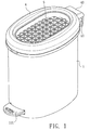
- the present invention relates to a garbage container, and more particularly to garbage container with a compress device for compressing the garbage received therein.
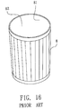
- a conventional garbage container in accordance with the prior art shown in Fig. 5 comprises a cylinder (8) with an opening (81) defined in a top portion of the cylinder and a receiving space (82) defined in the cylinder (8) for containing garbage.
- the garbage that we throw into the garbage container usually is fluffy such that the garbage will occupy most of the receiving space (82) even that the garbage container receives some garbage and needs to be often cleaned.
- the user usually compresses the garbage in the garbage container by his/her hands or foot. However, the user may be hurt by a sharpened object or a broken glass object during compressing the garbage in the garbage container.
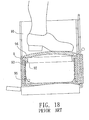
- the conventional garbage container comprises a cylinder (9) including a receiving space (91) defined in the cylinder (9).
- the receiving space has an upper opening (not numbered).
- a ring (92) is slidably mounted in the cylinder (9) and a spring (93) in compressively received in the cylinder (9).
- the spring has a first end abutting a bottom of the cylinder (9) and a second end abutting the ring (92).
- a cover (94) is pivotally mounted on the ring (92) for closing the receiving space (91) and has a diameter smaller than that of the receiving space (91).
- the garbage in the bag (95) is compressed when downward stepping the cover (94) and the restitution force of the spring (93) will push the ring (92) to the original position after the garbage being compressed to reduce volume for containing more garbage in the bag (95).
- the air in the bag (95) cannot drain from the bag (95) and is compressed when downward stepping the cover (94) and the ring (92).
- the compressed air in the bag (95) act against the user such that the garbage may not be fully compressed and the edge of the bag (95) will detach from the ring (92) and the spring (93) when the pressure of the compressed air in the bag (95) is greater than the clamping force between the ring (93) and the ring (92).
- the present invention has arisen to mitigate and/or obviate the disadvantages of the conventional garbage container.
- the main objective of the present invention is to provide an improved garbage container with a compress device for compressing the garbage that is received in the garbage container in accordance with the present invention.
- the garbage container in accordance with the present invention comprises a first cylinder having a first receiving space defined therein.
- a compress plate is reciprocally and movably received in the first cylinder for compressing the garbage in the garbage container.
- a cover is pivotally mounted on a top portion of the first cylinder.
- the cover has an opening defined therein and communicating with the first receiving space in the first cylinder.
- the cover includes a seat attached to a bottom of the cover and having an opening defined in the seat and corresponding to the opening in the cover.
- the opening in the cover allows a user's foot extending into the garbage container to step the compress plate for compressing garbage.
- a restituting device is mounted in the seat for providing a restitution force to the compress plate after compressing the garbage in the garbage container.
- a cover (4) is pivotally mounted on a top portion of the first cylinder (1) and a compress plate (5) is mounted under the cover (4) and separable relative to the cover (4).
- the compress plate (5) is reciprocally and longitudinally moved in the third cylinder (3).
- a restituting device (6) mounted in the cover (4) to provide a restitution force to the compress plate (5).
- the first cylinder (1) includes a first receiving space (11) therein for receiving the second cylinder (2).
- the first cylinder (1) has a lower close end and an upper open end.
- a first picot seat (12) laterally extends from an outer periphery of the first cylinder (1) for pivotally connected to the cover (4).
- a shaft (13) is mounted in a bottom of the first cylinder (1) and laterally extends through the first cylinder (1).
- the shaft (13) has a first end formed with a step portion and a second end opposite to the first end of the shaft (13).
- a linkage (132) has a first end pivotally connected to the second end of the shaft (31) and a second end pivotally connected to the cover (4) for lifting the cover (4).
- the second cylinder (2) is received in the first receiving space (11) in the first cylinder (1) and includes a second receiving space (21) defined in the second cylinder (2) for receiving the third cylinder (3).
- the second cylinder (2) has a lower close end and an upper open end.
- the third cylinder (3) has two opposite open ends and is received in the second receiving space (21) in the second cylinder (2) to hold open the bag such that the bag is received between the second cylinder (2) and third cylinder (3).
- Multiple slits (31) are defined in the third cylinder (3) and extend to a bottom of the third cylinder (3) such that the third cylinder (3) can slightly expand for more convenient holding open the bag.
- the cover (4) has a shape corresponding to that of the first cylinder (1).
- the cover (4) includes an opening (41) centrally defined therein to allow the user's foot extending into the garbage container to step the compress plate (5) for compressing garbage.
- a second pivot seat (43) laterally extends from the cover (4) for pivotally connected to the first pivot seat (12) of the first cylinder (1).
- An annular groove (411) is defined in a bottom of the cover (4) and surrounds the opening (41) in the cover (4).
- a seat (42) is snapped into the annular groove (411) and mounted on the bottom of the cover (4).
- the seat (42) has an opening (not numbered) defined therein and corresponding to the opening (41) in the cover (4).
- the seat (42) includes a first groove (421), a second groove (422), a third groove (423) and a fourth groove (424) defined in an upper side of the seat (42) and surrounding the opening (41) in the seat (42) for receiving the restituting device (6).
- the first groove (421) and the third groove (423) correspond to each other.
- the second groove (422) and the fourth groove (424) correspond to each other.
- a first stub (4211) upwardly extends from a bottom and near a first end of the first groove (421).
- a second stub (4221) extends from a bottom and near a first end of the second groove (422).
- a third stub (4231) extends from a bottom and near a first end of the third groove (423).
- a fourth stub (4241) extends from a bottom and near a first end of the fourth groove (424).
- a first roller (4212) is pivotally mounted on the upper side of the seat (42) near a second end of the first groove (421).
- a second roller (4222) is pivotally mounted on the upper side of the seat (42) near a second end of the second groove (422).
- a third roller (4232) is pivotally mounted on the upper side of the seat (42) near a second end of the third groove (423).
- a fourth roller (4242) is pivotally mounted on the upper side of the seat (42) near a second end of the fourth groove (424).
- the compress plate (5) is mounted under the seat (42) of the cover (4).
- the compress plate (5) has a shape corresponding to that of the cover (4) and greater than that of the opening (41) in the cover (4).
- the compress plate (5) has a skirt (51) upwardly extending therefrom within the opening (41) in the cover (4).
- the compress plate (5) has four sunken holes (52) defined in a bottom of the compress plate (5). Each sunken hole (52) corresponds to a corresponding one of the rollers (4212, 4222, 4232, 4242) of the cover (4).
- the restituting device (6) includes a first resilient member (61) received in the first groove (421) in the seat (42).
- the first resilient member (61) has a first end securely connected to the first stub (4211) and a second end connected to a first end of a first wire (65).
- the first wire (65) has a second end extending through the seat (42) and secured in a corresponding one of the four sunken holes (52) in the compress plate (5) after winding the first roller (4212).
- a second resilient member (62) is received in the second groove (422).
- the second resilient member (62) has a first end securely connected to the second stub (4221) and a second end connected to a firs end of a second wire (66).
- the second wire (66) has a second end extending through the seat (42) and secured in a corresponding one of the four sunken holes (52) in the compress plate (5) after winding the second roller (4222).
- a third resilient member (63) is received in the third groove (423).
- the third resilient member (63) has a first end securely connected to the third stub (4231) and a second end connected to a first end of a third wire (67).
- the third wire (67) has a second end extending through the seat (42) and secured in a corresponding one of the four sunken holes (52) in the compress plate (5) after winding the third roller (4232).
- a fourth resilient member (64) is received in the fourth groove (424).
- the fourth resilient member (64) has a first end secures on the fourth stub (4241) and a second end connected to a first end of a fourth wire (68).
- the fourth wire (68) has a second end extending through the seat (42) and secured in a corresponding one of the four sunken holes (52) in the compress plate (5).
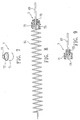
- the resilient members (61, 62, 63, 64) are springs.
- each end of the wires (65, 66, 67, 68) has an end piece (7) mounted thereon.
- the end piece (7) has a first section (71) and the second section (72) longitudinally extending from the first section of the end piece (7).
- the first section (71) has a diameter greater than that of the second section (72).
- a sunken hole (73) is defined in the end piece (71) for receiving the distal ends of each of the wires (65, 66, 67, 68) due to a tie formed on the ends of each of the wires (65, 66, 67, 68).
- the sunken hole (73) has a shape corresponding to that of the end piece (7) and extending through the end piece (7).
- the end piece (7) mounted on the first end of each of the wires (65, 66, 67, 68) is securely received in the second end of each of the resilient members (65, 66, 67, 68) and the end piece (7) mounted on the second end of each of the wires (65, 66, 67, 68) is received in a corresponding one of the four sunken holes (52) in the compress plate (5).
- the third cylinder (3) holds open the bag and received in the second cylinder (2).
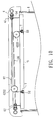
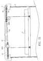
- the user can step the step portion (131) such that the cover (4) and the compress plate (5) are lifted, and the user can easily throw garbage into the garbage container.
- the user can downward step the compress plate (5) to compress the volume of the garbage received in the garbage container when the garbage is in a certain volume.
- the resilient members (61, 62, 63, 64) are pulled and extend by the wires (65, 66, 67, 68) when the compress plate (5) is downward moved in the third cylinder (3).
- the compress plate (5) will move to the original position thereof when the user stops stepping the compress plate (5) and the garbage is compressed due to the restitution force of the resilient members (61, 62, 63, 64).
- the garbage container with a compress device in accordance with the present invention includes several advantages as follow.
- the compress plate (5) has four slots (521) defined therein and each slot (521) is parallel to an axis of a corresponding one of the four sunken hole (52) in the compress plate (5) the laterally communicating with a corresponding one of the four sunken hole (52) in the compress plate (5) for easily mounting the second end of each of the wires (65, 66, 67, 68) in the sunken hole (52) in the compress plate (7).
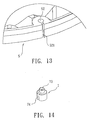
- the end piece (7) has a channel (74) longitudinally defined in an outer periphery of the end piece (7) and laterally communicating with the sunken hole (73) in the end piece (7) for easily mounting the opposite ends of each of the wires (65, 66, 67, 68) in a corresponding one of the end pieces (7).
- the garbage container with a compress device in accordance with the present invention further includes a metal plate (53) attached to a bottom of the compress plate (5) to enhance the structure strength of the compress plate (5) and prevent the compress plate (5) from being penetrated by a sharpened object during compressing the garbage in the garbage container.
- the invention provides for a garbage container with a compress device including a first cylinder having a first receiving space defined therein.
- a compress plate is reciprocally and movably received in the first cylinder for compressing the garbage in the garbage container.
- a cover is pivotally mounted on a top portion of the first cylinder.
- the cover has an opening defined therein and communicating with the first receiving space in the first cylinder.
- the cover includes a seat attached to a bottom of the cover and having an opening defined in the seat and corresponding to the opening in the cover.
- the opening in the cover allows a user's foot extending into the garbage container to step the compress plate for compressing garbage.
- a restituting device is mounted in the seat for providing a restitution force to the compress plate after compressing the garbage in the garbage container.
Landscapes
- Engineering & Computer Science (AREA)
- Mechanical Engineering (AREA)
- Refuse Receptacles (AREA)
- Semiconductor Memories (AREA)
- Read Only Memory (AREA)
Abstract
Description
Claims (20)
- A garbage container with a compress device for compressing the garbage received therein, comprising:a first cylinder having a first receiving space defined therein, a lower close end and an upper open end;a compress plate reciprocally and movably received in the first cylinder, the compress plate adapted to compress the garbage in the garbage container;a cover pivotally mounted on a top portion of the first cylinder, the cover having an opening defined therein and communicating with the first receiving space in the first cylinder, the cover including a seat attached to a bottom of the cover and having an opening defined in the seat and corresponding to the opening in the cover, the opening in the cover adapted to allow a user's foot extending into the garbage container to step the compress plate for compressing garbage; anda restituting device mounted in the seat for providing a restitution force to the compress plate after compressing the garbage in the garbage container.
- The garbage container as claimed in claim 1, wherein first cylinder comprises:a first pivot seat laterally extending from an outer periphery of the first cylinder for pivotally connected the cover;a shaft mounted in a bottom of the first cylinder and laterally extending through the cylinder, the shaft having a first end formed with a step portion and a second end opposite to the first end of the shaft; anda linkage having a first pivotally connected to the second of the shaft and a second end pivotally connected to the cover for lifting the cover.
- The garbage container as claimed in claim 2, wherein the cover has a shape corresponding to that of the first cylinder and includes:a second pivot seat laterally extending from the cover for pivotally connected to the first pivot seat of the first cylinder;an annular groove defined in a bottom of the cover and surrounding the opening in the cover such that the seat is snapped into the annular groove;a first, second, a third and a fourth grooves respectively defined in an upper side of the seat and surrounding the opening in the seat for receiving the restituting device, wherein the first groove corresponds to the third groove and the second groove correspond to the fourth groove;a first stub upwardly extending from a bottom of the first groove near a first end of the first groove;a second stub upwardly extending from a bottom of he second groove near a first end of the second groove;a third stub upwardly extending from a bottom of the third groove near a first end of the third groove;a fourth stub upwardly extending from a bottom of the fourth groove near a firs end of the fourth groove;a first roller pivotally mounted on the upper side of the seat near a second of the first groove;a second roller pivotally mounted on the upper side of the seat near a second end of the second groove;a third roller pivotally mounted on the upper side of the seat near a second end of the third groove; anda fourth roller pivotally mounted on the upper side of the seat near a second end of the fourth groove.
- The garbage container as claimed in claim 3, wherein the compress plate has a shape corresponding to that of the cover and greater than that of the opening in the cover, and comprises:a skirt upwardly extending from the compress plate within the opening in the cover; andfour sunken holes defined in a bottom of the compress plate and each corresponding to a corresponding one of the first, second, third and the fourth rollers of the cover.
- The garbage container as claimed in claim 4, wherein the restituting device comprises:a first resilient member received in the first groove in the seat, the first resilient member having a first end securely connected to the first stub and a second end connected to first end of a first wire, the first wire having a second end extending through the seat and secured in a corresponding one of the four sunken holes in the compress plate after winding the first roller;a second resilient member received in the second groove in the seat, the second resilient member having a first end securely connected to the second stub and a second end connected to a first end of a second wire, the second wire having a second end extending through the seat and secured in a corresponding one of the four sunken holes in the compress plate after winding the second roller;a third resilient member received in the third groove in the seat, the third resilient member having a first end securely connected to the third stub and a second end connected to a first end of a third wire, the third wire having a second end extending through the seat and secured in the a corresponding one the four sunken holes in the compress plate after winding the third roller; anda fourth resilient member received in the fourth groove in the seat, the fourth resilient member having a first end securely connected to the fourth stub and a second connected to a first end of a fourth wire, the fourth wire having a second end extending through the seat and secured in a corresponding one of the four sunken holes in the compress plate after winding the fourth roller.
- The garbage container as claimed in claim 5, wherein the first resilient member, the second resilient member, the third resilient member and the fourth resilient members are springs.
- The garbage container as claimed in claim 5, wherein the first end and the second end of each of the first wire, the second wire, the third wire and the fourth wire respectively has an end piece mounted thereon, the end piece comprising a first section and a second section longitudinally extending from the first section, the first section having a diameter greater than that of the second section, a sunken hole defined in the end piece for receiving the first/second end of each of the first, the second the third and the fourth wires due to a tie formed on the first/second end of each of the first, the second the third and the fourth wires, the sunken hole in the end piece having a shape corresponding to that of the end piece and extending through the end piece, the end piece mounted on the first end of each of the first, the second the third and the fourth wires being securely received in the second end of each of the first, the second the third and the fourth resilient members, the end piece mounted on the second end of each of the first, the second the third and the fourth wires being received in a corresponding one of the four sunken holes in the compress plate.
- The garbage container as claimed in claim 6, wherein the first end and the second end of each of the first wire, the second wire, the third wire and the fourth wire respectively has an end piece mounted thereon, the end piece comprising a first section and a second section longitudinally extending from the first section, the first section having a diameter greater than that of the second section, a sunken hole defined in the end piece for receiving the first/second end of each of the first, the second the third and the fourth wires due to a tie formed on the first/second end of each of the first, the second the third and the fourth wires, the sunken hole in the end piece having a shape corresponding to that of the end piece and extending through the end piece, the end piece mounted on the first end of each of the first, the second the third and the fourth wires being securely received in the second end of each of the first, the second the third and the fourth resilient members, the end piece mounted on the second end of each of the first, the second the third and the fourth wires being received in a corresponding one of the four sunken holes in the compress plate.
- The garbage container as claimed in claim 8, wherein the end piece comprises the end piece comprises a channel longitudinally defined in an outer periphery of the end piece and laterally communicating with the sunken hole in the end piece for easily mounted the first/second end of each of the first, the second, the third and the fourth wires in a corresponding one of the end piece.
- The garbage container as claimed in claim 4, wherein the compress plate comprises four slots defined therein, each slot parallel to an axis of a corresponding one of the four sunken holes in the compress plate and laterally communicating with a corresponding one of the four sunken holes in the compress plate for easily mounted the second end of each of the first, the second, the third and the fourth wires.
- The garbage container as claimed in claim 1 further comprising a second cylinder received in the first receiving space in the first cylinder and adapted to receive a bag for receiving the garbage, the second cylinder including a second receiving defined therein, the second cylinder having a lower close end and an open upper end.
- The garbage container as claimed in claim 2 further comprising a second cylinder received in the first receiving space in the first cylinder and adapted to receive a bag for receiving the garbage, the second cylinder including a second receiving defined therein, the second cylinder having a lower close end and an open upper end.
- The garbage container as claimed in claim 3 further comprising a second cylinder received in the first receiving space in the first cylinder and adapted to receive a bag for receiving the garbage, the second cylinder including a second receiving defined therein, the second cylinder having a lower close end and an open upper end.
- The garbage container as claimed in claim 4 further comprising a second cylinder received in the first receiving space in the first cylinder and adapted to receive a bag for receiving the garbage, the second cylinder including a second receiving defined therein, the second cylinder having a lower close end and an open upper end.
- The garbage container as claimed in claim 5 further comprising a second cylinder received in the first receiving space in the first cylinder and adapted to receive a bag for receiving the garbage, the second cylinder including a second receiving defined therein, the second cylinder having a lower close end and an open upper end.
- The garbage container as claimed in claim 11 further comprising a third cylinder received in the second receiving space in the second cylinder and adapted to hold open the bag such that the bag is received between the second cylinder and the third cylinder.
- The garbage container as claimed in claim 12 further comprising a third cylinder received in the second receiving space in the second cylinder and adapted to hold open the bag such that the bag is received between the second cylinder and the third cylinder.
- The garbage container as claimed in claim 13 further comprising a third cylinder received in the second receiving space in the second cylinder and adapted to hold open the bag such that the bag is received between the second cylinder and the third cylinder.
- The garbage container as claimed in claim 14 further comprising a third cylinder received in the second receiving space in the second cylinder and adapted to hold open the bag such that the bag is received between the second cylinder and the third cylinder.
- The garbage container as claimed in claim 15 further comprising a third cylinder received in the second receiving space in the second cylinder and adapted to hold open the bag such that the bag is received between the second cylinder and the third cylinder.
Applications Claiming Priority (3)
| Application Number | Priority Date | Filing Date | Title |
|---|---|---|---|
| CN02217666U | 2002-05-24 | ||
| CN02217666U CN2552866Y (en) | 2002-05-24 | 2002-05-24 | Trash cans that can compress the volume of garbage |
| US10/178,476 US6709923B2 (en) | 2002-05-24 | 2002-06-25 | Method for manufacturing an array structure in integrated circuits |
Publications (2)
| Publication Number | Publication Date |
|---|---|
| EP1364893A1 true EP1364893A1 (en) | 2003-11-26 |
| EP1364893B1 EP1364893B1 (en) | 2006-08-23 |
Family
ID=32298975
Family Applications (1)
| Application Number | Title | Priority Date | Filing Date |
|---|---|---|---|
| EP03007146A Expired - Lifetime EP1364893B1 (en) | 2002-05-24 | 2003-03-28 | Garbage container with compressing device |
Country Status (3)
| Country | Link |
|---|---|
| US (1) | US6709923B2 (en) |
| EP (1) | EP1364893B1 (en) |
| CN (1) | CN2552866Y (en) |
Cited By (3)
| Publication number | Priority date | Publication date | Assignee | Title |
|---|---|---|---|---|
| US6910412B2 (en) * | 2002-06-19 | 2005-06-28 | Wen-Hsiung Ko | Garbage container with a compress device for compressing the garbage received therein |
| DE102005014044A1 (en) * | 2005-03-23 | 2006-09-28 | Shu-Pei Huang | Hinged lid container used as a rubbish container comprises a foot part having a projection with a maximum transverse direction in a longitudinal direction and a minimum extension |
| CN112317503A (en) * | 2020-09-15 | 2021-02-05 | 储承勇 | Polystyrene plastic products recovery unit |
Families Citing this family (3)
| Publication number | Priority date | Publication date | Assignee | Title |
|---|---|---|---|---|
| US7569309B2 (en) * | 2005-11-09 | 2009-08-04 | Texas Instruments Incorporated | Gate critical dimension variation by use of ghost features |
| US7919231B2 (en) * | 2007-09-04 | 2011-04-05 | Hitachi Global Storage Technologies Netherlands B.V. | Photolithographic method and mask devices utilized for multiple exposures in the field of a feature |
| CN101670928B (en) * | 2009-08-31 | 2012-05-30 | 高学才 | Intelligent electric compression dustbin |
Citations (5)
| Publication number | Priority date | Publication date | Assignee | Title |
|---|---|---|---|---|
| GB466260A (en) * | 1936-12-03 | 1937-05-25 | E T Everton Ltd | Improvements in indoor refuse bins |
| US3736863A (en) * | 1971-05-21 | 1973-06-05 | Black And Decker Towson | Trash compactor |
| DE2912851A1 (en) * | 1979-03-30 | 1980-10-02 | Manfred Hattensauer | Refuse bin with compression unit - consists of weighted piston held within lid, and includes actuator and retaining unit |
| JP2001240206A (en) * | 2000-02-27 | 2001-09-04 | Kurazo Sakurai | Garbage container with volume reduction device |
| DE20206109U1 (en) * | 2002-04-18 | 2002-08-22 | Ko, Wen-Hsiung, Fong-Yuan, Taichung | Trash can with the possibility of garbage compaction |
Family Cites Families (3)
| Publication number | Priority date | Publication date | Assignee | Title |
|---|---|---|---|---|
| US4569120A (en) * | 1983-03-07 | 1986-02-11 | Signetics Corporation | Method of fabricating a programmable read-only memory cell incorporating an antifuse utilizing ion implantation |
| US5060190A (en) * | 1990-09-18 | 1991-10-22 | Industrial Technology Research Institute | Read only memory with write operation using mask |
| TW440851B (en) * | 1999-09-30 | 2001-06-16 | Macronix Int Co Ltd | Fabricating method of binary code pattern for read only memory |
-
2002
- 2002-05-24 CN CN02217666U patent/CN2552866Y/en not_active Expired - Fee Related
- 2002-06-25 US US10/178,476 patent/US6709923B2/en not_active Expired - Lifetime
-
2003
- 2003-03-28 EP EP03007146A patent/EP1364893B1/en not_active Expired - Lifetime
Patent Citations (5)
| Publication number | Priority date | Publication date | Assignee | Title |
|---|---|---|---|---|
| GB466260A (en) * | 1936-12-03 | 1937-05-25 | E T Everton Ltd | Improvements in indoor refuse bins |
| US3736863A (en) * | 1971-05-21 | 1973-06-05 | Black And Decker Towson | Trash compactor |
| DE2912851A1 (en) * | 1979-03-30 | 1980-10-02 | Manfred Hattensauer | Refuse bin with compression unit - consists of weighted piston held within lid, and includes actuator and retaining unit |
| JP2001240206A (en) * | 2000-02-27 | 2001-09-04 | Kurazo Sakurai | Garbage container with volume reduction device |
| DE20206109U1 (en) * | 2002-04-18 | 2002-08-22 | Ko, Wen-Hsiung, Fong-Yuan, Taichung | Trash can with the possibility of garbage compaction |
Non-Patent Citations (1)
| Title |
|---|
| PATENT ABSTRACTS OF JAPAN vol. 2000, no. 26 1 July 2002 (2002-07-01) * |
Cited By (4)
| Publication number | Priority date | Publication date | Assignee | Title |
|---|---|---|---|---|
| US6910412B2 (en) * | 2002-06-19 | 2005-06-28 | Wen-Hsiung Ko | Garbage container with a compress device for compressing the garbage received therein |
| DE102005014044A1 (en) * | 2005-03-23 | 2006-09-28 | Shu-Pei Huang | Hinged lid container used as a rubbish container comprises a foot part having a projection with a maximum transverse direction in a longitudinal direction and a minimum extension |
| CN112317503A (en) * | 2020-09-15 | 2021-02-05 | 储承勇 | Polystyrene plastic products recovery unit |
| CN112317503B (en) * | 2020-09-15 | 2022-03-01 | 济南鼎泰保温建材有限公司 | Polystyrene plastic products recovery unit |
Also Published As
| Publication number | Publication date |
|---|---|
| US6709923B2 (en) | 2004-03-23 |
| EP1364893B1 (en) | 2006-08-23 |
| US20030235950A1 (en) | 2003-12-25 |
| CN2552866Y (en) | 2003-05-28 |
Similar Documents
| Publication | Publication Date | Title |
|---|---|---|
| US5826928A (en) | Multifunctional device for catching and holding an object | |
| US6910412B2 (en) | Garbage container with a compress device for compressing the garbage received therein | |
| US6345725B1 (en) | Waste bin structure | |
| US6102343A (en) | Step and lift refuse liner removal system | |
| US6435444B1 (en) | Reel for a suspended sunshade | |
| US6983685B2 (en) | Garbage can capable of compresing garbage volume | |
| EP1475011A1 (en) | Cosmetics case | |
| US5632188A (en) | Ergopunch | |
| US6484436B1 (en) | Prey trap without using bait | |
| US8567422B2 (en) | Umbrella | |
| CA2318015A1 (en) | Ring binder having actuating lever with cushion member | |
| EP1364893B1 (en) | Garbage container with compressing device | |
| US6226834B1 (en) | Handle structure for a luggage | |
| EP0640538A1 (en) | Portable garbage can | |
| GB2395679A (en) | Tree pruner | |
| US6223392B1 (en) | Retractable handle assembly | |
| US20080149155A1 (en) | Handy hand walking cane | |
| US20080023474A1 (en) | Garbage can | |
| EP1204297A3 (en) | Microspeaker | |
| CN201356511Y (en) | Upper cover opening device of dust collector | |
| KR200448328Y1 (en) | Squeezable dustbin | |
| US20020162566A1 (en) | Face powder compact | |
| KR200212889Y1 (en) | press type waste bin | |
| US20090266379A1 (en) | Hair clamping device | |
| EP1120060A3 (en) | Detergent container with massage brush |
Legal Events
| Date | Code | Title | Description |
|---|---|---|---|
| PUAI | Public reference made under article 153(3) epc to a published international application that has entered the european phase |
Free format text: ORIGINAL CODE: 0009012 |
|
| AK | Designated contracting states |
Kind code of ref document: A1 Designated state(s): AT BE BG CH CY CZ DE DK EE ES FI FR GB GR HU IE IT LI LU MC NL PT RO SE SI SK TR |
|
| AX | Request for extension of the european patent |
Extension state: AL LT LV MK |
|
| 17P | Request for examination filed |
Effective date: 20031211 |
|
| AKX | Designation fees paid |
Designated state(s): AT BE BG CH CY CZ DE DK EE ES FI FR GB GR HU IE IT LI LU MC NL PT RO SE SI SK TR |
|
| 17Q | First examination report despatched |
Effective date: 20040826 |
|
| GRAP | Despatch of communication of intention to grant a patent |
Free format text: ORIGINAL CODE: EPIDOSNIGR1 |
|
| RTI1 | Title (correction) |
Free format text: GARBAGE CONTAINER WITH COMPRESSING DEVICE |
|
| GRAS | Grant fee paid |
Free format text: ORIGINAL CODE: EPIDOSNIGR3 |
|
| GRAA | (expected) grant |
Free format text: ORIGINAL CODE: 0009210 |
|
| AK | Designated contracting states |
Kind code of ref document: B1 Designated state(s): AT BE BG CH CY CZ DE DK EE ES FI FR GB GR HU IE IT LI LU MC NL PT RO SE SI SK TR |
|
| PG25 | Lapsed in a contracting state [announced via postgrant information from national office to epo] |
Ref country code: IT Free format text: LAPSE BECAUSE OF FAILURE TO SUBMIT A TRANSLATION OF THE DESCRIPTION OR TO PAY THE FEE WITHIN THE PRESCRIBED TIME-LIMIT;WARNING: LAPSES OF ITALIAN PATENTS WITH EFFECTIVE DATE BEFORE 2007 MAY HAVE OCCURRED AT ANY TIME BEFORE 2007. THE CORRECT EFFECTIVE DATE MAY BE DIFFERENT FROM THE ONE RECORDED. Effective date: 20060823 Ref country code: RO Free format text: LAPSE BECAUSE OF FAILURE TO SUBMIT A TRANSLATION OF THE DESCRIPTION OR TO PAY THE FEE WITHIN THE PRESCRIBED TIME-LIMIT Effective date: 20060823 Ref country code: SK Free format text: LAPSE BECAUSE OF FAILURE TO SUBMIT A TRANSLATION OF THE DESCRIPTION OR TO PAY THE FEE WITHIN THE PRESCRIBED TIME-LIMIT Effective date: 20060823 Ref country code: SI Free format text: LAPSE BECAUSE OF FAILURE TO SUBMIT A TRANSLATION OF THE DESCRIPTION OR TO PAY THE FEE WITHIN THE PRESCRIBED TIME-LIMIT Effective date: 20060823 Ref country code: NL Free format text: LAPSE BECAUSE OF FAILURE TO SUBMIT A TRANSLATION OF THE DESCRIPTION OR TO PAY THE FEE WITHIN THE PRESCRIBED TIME-LIMIT Effective date: 20060823 Ref country code: BE Free format text: LAPSE BECAUSE OF FAILURE TO SUBMIT A TRANSLATION OF THE DESCRIPTION OR TO PAY THE FEE WITHIN THE PRESCRIBED TIME-LIMIT Effective date: 20060823 |
|
| REG | Reference to a national code |
Ref country code: GB Ref legal event code: FG4D |
|
| REG | Reference to a national code |
Ref country code: CH Ref legal event code: EP |
|
| REG | Reference to a national code |
Ref country code: IE Ref legal event code: FG4D |
|
| REF | Corresponds to: |
Ref document number: 60307718 Country of ref document: DE Date of ref document: 20061005 Kind code of ref document: P |
|
| PG25 | Lapsed in a contracting state [announced via postgrant information from national office to epo] |
Ref country code: DK Free format text: LAPSE BECAUSE OF FAILURE TO SUBMIT A TRANSLATION OF THE DESCRIPTION OR TO PAY THE FEE WITHIN THE PRESCRIBED TIME-LIMIT Effective date: 20061123 Ref country code: BG Free format text: LAPSE BECAUSE OF FAILURE TO SUBMIT A TRANSLATION OF THE DESCRIPTION OR TO PAY THE FEE WITHIN THE PRESCRIBED TIME-LIMIT Effective date: 20061123 Ref country code: SE Free format text: LAPSE BECAUSE OF FAILURE TO SUBMIT A TRANSLATION OF THE DESCRIPTION OR TO PAY THE FEE WITHIN THE PRESCRIBED TIME-LIMIT Effective date: 20061123 |
|
| PG25 | Lapsed in a contracting state [announced via postgrant information from national office to epo] |
Ref country code: DE Free format text: LAPSE BECAUSE OF FAILURE TO SUBMIT A TRANSLATION OF THE DESCRIPTION OR TO PAY THE FEE WITHIN THE PRESCRIBED TIME-LIMIT Effective date: 20061124 |
|
| PG25 | Lapsed in a contracting state [announced via postgrant information from national office to epo] |
Ref country code: ES Free format text: LAPSE BECAUSE OF FAILURE TO SUBMIT A TRANSLATION OF THE DESCRIPTION OR TO PAY THE FEE WITHIN THE PRESCRIBED TIME-LIMIT Effective date: 20061204 |
|
| PG25 | Lapsed in a contracting state [announced via postgrant information from national office to epo] |
Ref country code: PT Free format text: LAPSE BECAUSE OF FAILURE TO SUBMIT A TRANSLATION OF THE DESCRIPTION OR TO PAY THE FEE WITHIN THE PRESCRIBED TIME-LIMIT Effective date: 20070125 |
|
| NLV1 | Nl: lapsed or annulled due to failure to fulfill the requirements of art. 29p and 29m of the patents act | ||
| REG | Reference to a national code |
Ref country code: CH Ref legal event code: NV Representative=s name: TROESCH SCHEIDEGGER WERNER AG |
|
| ET | Fr: translation filed | ||
| PLBE | No opposition filed within time limit |
Free format text: ORIGINAL CODE: 0009261 |
|
| STAA | Information on the status of an ep patent application or granted ep patent |
Free format text: STATUS: NO OPPOSITION FILED WITHIN TIME LIMIT |
|
| 26N | No opposition filed |
Effective date: 20070524 |
|
| PG25 | Lapsed in a contracting state [announced via postgrant information from national office to epo] |
Ref country code: IE Free format text: LAPSE BECAUSE OF NON-PAYMENT OF DUE FEES Effective date: 20070328 Ref country code: MC Free format text: LAPSE BECAUSE OF NON-PAYMENT OF DUE FEES Effective date: 20070331 |
|
| PG25 | Lapsed in a contracting state [announced via postgrant information from national office to epo] |
Ref country code: GR Free format text: LAPSE BECAUSE OF FAILURE TO SUBMIT A TRANSLATION OF THE DESCRIPTION OR TO PAY THE FEE WITHIN THE PRESCRIBED TIME-LIMIT Effective date: 20061124 |
|
| PG25 | Lapsed in a contracting state [announced via postgrant information from national office to epo] |
Ref country code: EE Free format text: LAPSE BECAUSE OF FAILURE TO SUBMIT A TRANSLATION OF THE DESCRIPTION OR TO PAY THE FEE WITHIN THE PRESCRIBED TIME-LIMIT Effective date: 20060823 |
|
| PG25 | Lapsed in a contracting state [announced via postgrant information from national office to epo] |
Ref country code: CZ Free format text: LAPSE BECAUSE OF NON-PAYMENT OF DUE FEES Effective date: 20080328 |
|
| PG25 | Lapsed in a contracting state [announced via postgrant information from national office to epo] |
Ref country code: LU Free format text: LAPSE BECAUSE OF NON-PAYMENT OF DUE FEES Effective date: 20070328 Ref country code: CY Free format text: LAPSE BECAUSE OF FAILURE TO SUBMIT A TRANSLATION OF THE DESCRIPTION OR TO PAY THE FEE WITHIN THE PRESCRIBED TIME-LIMIT Effective date: 20060823 |
|
| PG25 | Lapsed in a contracting state [announced via postgrant information from national office to epo] |
Ref country code: TR Free format text: LAPSE BECAUSE OF FAILURE TO SUBMIT A TRANSLATION OF THE DESCRIPTION OR TO PAY THE FEE WITHIN THE PRESCRIBED TIME-LIMIT Effective date: 20060823 Ref country code: HU Free format text: LAPSE BECAUSE OF FAILURE TO SUBMIT A TRANSLATION OF THE DESCRIPTION OR TO PAY THE FEE WITHIN THE PRESCRIBED TIME-LIMIT Effective date: 20070224 |
|
| PGFP | Annual fee paid to national office [announced via postgrant information from national office to epo] |
Ref country code: CH Payment date: 20120323 Year of fee payment: 10 |
|
| PGFP | Annual fee paid to national office [announced via postgrant information from national office to epo] |
Ref country code: FI Payment date: 20120326 Year of fee payment: 10 |
|
| PGFP | Annual fee paid to national office [announced via postgrant information from national office to epo] |
Ref country code: AT Payment date: 20120327 Year of fee payment: 10 |
|
| PG25 | Lapsed in a contracting state [announced via postgrant information from national office to epo] |
Ref country code: FI Free format text: LAPSE BECAUSE OF NON-PAYMENT OF DUE FEES Effective date: 20130328 |
|
| REG | Reference to a national code |
Ref country code: CH Ref legal event code: PL |
|
| REG | Reference to a national code |
Ref country code: AT Ref legal event code: MM01 Ref document number: 337238 Country of ref document: AT Kind code of ref document: T Effective date: 20130328 |
|
| PG25 | Lapsed in a contracting state [announced via postgrant information from national office to epo] |
Ref country code: AT Free format text: LAPSE BECAUSE OF NON-PAYMENT OF DUE FEES Effective date: 20130328 Ref country code: LI Free format text: LAPSE BECAUSE OF NON-PAYMENT OF DUE FEES Effective date: 20130331 Ref country code: CH Free format text: LAPSE BECAUSE OF NON-PAYMENT OF DUE FEES Effective date: 20130331 |
|
| REG | Reference to a national code |
Ref country code: FR Ref legal event code: PLFP Year of fee payment: 14 |
|
| REG | Reference to a national code |
Ref country code: FR Ref legal event code: PLFP Year of fee payment: 15 |
|
| PGFP | Annual fee paid to national office [announced via postgrant information from national office to epo] |
Ref country code: FR Payment date: 20170321 Year of fee payment: 15 |
|
| PGFP | Annual fee paid to national office [announced via postgrant information from national office to epo] |
Ref country code: GB Payment date: 20170328 Year of fee payment: 15 Ref country code: CZ Payment date: 20170321 Year of fee payment: 15 |
|
| PGFP | Annual fee paid to national office [announced via postgrant information from national office to epo] |
Ref country code: IT Payment date: 20170327 Year of fee payment: 15 |
|
| GBPC | Gb: european patent ceased through non-payment of renewal fee |
Effective date: 20180328 |
|
| PG25 | Lapsed in a contracting state [announced via postgrant information from national office to epo] |
Ref country code: CZ Free format text: LAPSE BECAUSE OF NON-PAYMENT OF DUE FEES Effective date: 20180328 |
|
| PG25 | Lapsed in a contracting state [announced via postgrant information from national office to epo] |
Ref country code: IT Free format text: LAPSE BECAUSE OF NON-PAYMENT OF DUE FEES Effective date: 20180328 Ref country code: GB Free format text: LAPSE BECAUSE OF NON-PAYMENT OF DUE FEES Effective date: 20180328 |
|
| PG25 | Lapsed in a contracting state [announced via postgrant information from national office to epo] |
Ref country code: FR Free format text: LAPSE BECAUSE OF NON-PAYMENT OF DUE FEES Effective date: 20180331 |