EP1364736A1 - Method, kit and insert for replacing damaged threads - Google Patents
Method, kit and insert for replacing damaged threads Download PDFInfo
- Publication number
- EP1364736A1 EP1364736A1 EP03010346A EP03010346A EP1364736A1 EP 1364736 A1 EP1364736 A1 EP 1364736A1 EP 03010346 A EP03010346 A EP 03010346A EP 03010346 A EP03010346 A EP 03010346A EP 1364736 A1 EP1364736 A1 EP 1364736A1
- Authority
- EP
- European Patent Office
- Prior art keywords
- threads
- insert
- tap
- previous
- kit
- Prior art date
- Legal status (The legal status is an assumption and is not a legal conclusion. Google has not performed a legal analysis and makes no representation as to the accuracy of the status listed.)
- Withdrawn
Links
- 238000000034 method Methods 0.000 title claims abstract description 16
- 230000007246 mechanism Effects 0.000 claims abstract description 32
- 230000004323 axial length Effects 0.000 claims abstract description 25
- 238000003801 milling Methods 0.000 claims abstract description 19
- 230000014759 maintenance of location Effects 0.000 claims abstract description 14
- 239000000463 material Substances 0.000 claims abstract description 12
- 238000007789 sealing Methods 0.000 claims description 5
- 239000000565 sealant Substances 0.000 claims description 4
- 230000006835 compression Effects 0.000 claims description 3
- 238000007906 compression Methods 0.000 claims description 3
- 239000000853 adhesive Substances 0.000 description 2
- 230000001070 adhesive effect Effects 0.000 description 2
- 230000008602 contraction Effects 0.000 description 2
- 230000002950 deficient Effects 0.000 description 2
- 238000012986 modification Methods 0.000 description 2
- 230000004048 modification Effects 0.000 description 2
- 229910000975 Carbon steel Inorganic materials 0.000 description 1
- XAGFODPZIPBFFR-UHFFFAOYSA-N aluminium Chemical compound [Al] XAGFODPZIPBFFR-UHFFFAOYSA-N 0.000 description 1
- 229910052782 aluminium Inorganic materials 0.000 description 1
- 239000010962 carbon steel Substances 0.000 description 1
- 238000005266 casting Methods 0.000 description 1
- 239000012634 fragment Substances 0.000 description 1
- 239000007789 gas Substances 0.000 description 1
- 238000012423 maintenance Methods 0.000 description 1
- 229920002631 room-temperature vulcanizate silicone Polymers 0.000 description 1
- 239000007779 soft material Substances 0.000 description 1
- 230000007704 transition Effects 0.000 description 1
Images


Classifications
-
- B—PERFORMING OPERATIONS; TRANSPORTING
- B23—MACHINE TOOLS; METAL-WORKING NOT OTHERWISE PROVIDED FOR
- B23G—THREAD CUTTING; WORKING OF SCREWS, BOLT HEADS, OR NUTS, IN CONJUNCTION THEREWITH
- B23G9/00—Working screws, bolt heads, or nuts in conjunction with thread cutting, e.g. slotting screw heads or shanks, removing burrs from screw heads or shanks; Finishing, e.g. polishing, any screw-thread
- B23G9/009—Thread cleaning or repairing
-
- B—PERFORMING OPERATIONS; TRANSPORTING
- B23—MACHINE TOOLS; METAL-WORKING NOT OTHERWISE PROVIDED FOR
- B23B—TURNING; BORING
- B23B2260/00—Details of constructional elements
- B23B2260/09—Knurled surfaces
-
- Y—GENERAL TAGGING OF NEW TECHNOLOGICAL DEVELOPMENTS; GENERAL TAGGING OF CROSS-SECTIONAL TECHNOLOGIES SPANNING OVER SEVERAL SECTIONS OF THE IPC; TECHNICAL SUBJECTS COVERED BY FORMER USPC CROSS-REFERENCE ART COLLECTIONS [XRACs] AND DIGESTS
- Y10—TECHNICAL SUBJECTS COVERED BY FORMER USPC
- Y10T—TECHNICAL SUBJECTS COVERED BY FORMER US CLASSIFICATION
- Y10T29/00—Metal working
- Y10T29/49—Method of mechanical manufacture
- Y10T29/49718—Repairing
- Y10T29/49732—Repairing by attaching repair preform, e.g., remaking, restoring, or patching
- Y10T29/49744—Screw threaded preform
-
- Y—GENERAL TAGGING OF NEW TECHNOLOGICAL DEVELOPMENTS; GENERAL TAGGING OF CROSS-SECTIONAL TECHNOLOGIES SPANNING OVER SEVERAL SECTIONS OF THE IPC; TECHNICAL SUBJECTS COVERED BY FORMER USPC CROSS-REFERENCE ART COLLECTIONS [XRACs] AND DIGESTS
- Y10—TECHNICAL SUBJECTS COVERED BY FORMER USPC
- Y10T—TECHNICAL SUBJECTS COVERED BY FORMER US CLASSIFICATION
- Y10T408/00—Cutting by use of rotating axially moving tool
- Y10T408/03—Processes
-
- Y—GENERAL TAGGING OF NEW TECHNOLOGICAL DEVELOPMENTS; GENERAL TAGGING OF CROSS-SECTIONAL TECHNOLOGIES SPANNING OVER SEVERAL SECTIONS OF THE IPC; TECHNICAL SUBJECTS COVERED BY FORMER USPC CROSS-REFERENCE ART COLLECTIONS [XRACs] AND DIGESTS
- Y10—TECHNICAL SUBJECTS COVERED BY FORMER USPC
- Y10T—TECHNICAL SUBJECTS COVERED BY FORMER US CLASSIFICATION
- Y10T408/00—Cutting by use of rotating axially moving tool
- Y10T408/55—Cutting by use of rotating axially moving tool with work-engaging structure other than Tool or tool-support
- Y10T408/569—Bushing
Definitions
- the present invention relates to replacing damaged threads with an insert and associated methods and kits; and more particularly to such inserts and associated methods and kits for spark plug hole threads.
- Threads in a spark plug hole in a cylinder head can be defective.
- some newly designed engines utilize deep recessed holes for their spark plugs. These holes are typically located in areas which are hard to see and reach. Maintenance of these engines requires that the spark plugs be replaced and/or adjusted repeatedly during the engine's life.
- today's engine block castings are often made of relatively soft materials, such as aluminum. Consequently, the threads may become stripped or otherwise damaged to such an extent as to render them unusable. Replacing defective threads avoids the necessity of replacing entire cylinder head, which is a relatively expensive part of the engine.
- an insert useful for replacing damaged threads in a hole has an inner surface having inner threads corresponding to the damaged threads being replaced.
- the insert also has an outer surface having outer threads extending a length that is greater than the length of the damaged threads.
- a kit useful for replacing damaged threads in a hole includes the insert and a tap having a thread milling section, and a retention mechanism implement.
- the retention mechanism implement is an expansion tool.
- a method for replacing damaged threads in a hole includes enlarging the diameter of the hole and milling threads along the enlarged hole over a length greater than the length of the threads being replaced.
- an insert having outer threads along a length greater than the original threaded segment and having inner threads corresponding to the original threaded segment is threaded into the enlarged hole on the milled threads. Thereafter, the insert is fixed against rotation.
- a kit useful for replacing damaged threads and a hole includes an insert having outer threads and a tap.
- the tap has a thread milling segment adapted to mill threads to cooperate with the outer threads.
- the tap has a torque segment adapted to enable engagement of a torque generating tool with the tap while any engagement mechanisms of the torque generating tool remain substantially within an outer radial dimension of the tap.
- a kit useful for replacing damaged threads and a hole includes an insert having outer threads and a tap.
- the tap has a thread milling segment adapted to mill threads to cooperate with the outer threads.
- the tap has a torque engagement mechanism adapted to engage a cooperating engagement mechanism of a torque generating tool.
- the engagement mechanisms have a maximum radial dimension that is substantially equal to or less than a maximum radial dimension of the tap.
- the kit 20 basically includes an insert 22, a tap 24, and an expanding tool 26.
- the insert 22 includes threads 28 located on its inner cylindrical surface. These inner threads 28 extend only about one-third of the overall axial length of the insert 22. Preferably, these inner threads 28 extend less than about 75 percent of the overall axial length of the insert 22; more preferably, less than about two-thirds of the overall axial length of the insert 22; even more preferably, less than about 50 percent of the overall axial length of the insert 22; and most preferably, less than about one-third the overall axial length of the insert 22.
- inner threads 28 correspond to the original threads 32 of the spark plug hole 30, as seen in Figure 2.
- the inner threads 28 are not necessarily of the identical axial length as the original threads 32 of the hole 30, although they correspond to the original threads 32 of the spark plug hole 30.
- the inner threads 28 preferably have an axial length which is about the same as the original damaged threads 32 being replaced; more preferably, have an axial length which is the same or less than the original threads 32; and even more preferably, have an axial length which is substantially identical to the original threads 32.
- At least the inner threads 28 of the insert are preferably made of a material that is harder than the material of the engine block 36.
- the inner threads 28 may alternatively be treated or coated to increase their strength.
- the inner threads 28 of the insert are less susceptible to damage than the original spark plug hole threads 32.
- a particularly preferred material for constructing the insert 22 is carbon steel.
- the insert 22 preferably has a substantially identical heat expansion and contraction rate. In other words, the expansion and contraction of the insert 22 due to heat is preferably substantially identical to that of the surrounding engine block 36 material. This helps ensure a good seal is maintained between the insert 22 and the engine block during extended use.
- the insert 22 includes outer threads 34 which preferably encompass the entire overall axial length of the outer surface of the insert 22, as illustrated.
- the outer threads 34 preferably axially extend at least about 1.25 times the axial length of the original, damaged threads 32; more preferably, at least about 1.6 times the axial length of the original, damaged threads 32; even more preferably, at least about 2 times the axial length of the original, damaged threads 32; and most preferably, at least about 3 times the axial length of original, damaged threads 32.
- the outer threads 34 include knurled threads near the distal end of the insert 34'.
- the knurled threads 34' act as teeth and help imbed the insert 22 into the inner wall of the expanded hole 30 of the engine block 36, as discussed hereinafter. Consequently, the knurled threads 34' act as a retention mechanism which helps prevent the insert 22 from rotating out of the engine block 36, after the insert 22 has been threaded into the enlarged hole 30.
- a flange is provided at the distal or outer axial end of the insert
- the flange may operate as a stop to frictionally engage the insert in place.
- the radial outer surface of any such flange would include threads thereon.
- the axial length of the threads are preferably maximized to provide threads along the entire axial length of the outer surface of the insert
- the tap 24 includes a smaller diameter threaded segment 38 at its distal end.
- the threads 40 of this segment 38 are adapted to cooperate with the original damaged threads 32 to help guide and pull the tap 24 into the original spark plug hole 30.
- a generally conically shaped reamer segment 42 is adapted to ream out the damaged threads 32 and the hole 30 to an enlarged diameter.
- This reamer segment 42 transitions to a larger diameter thread milling segment 44.
- the thread milling segment 44 is adapted to mill new larger diameter threads for the insert 22 into the engine block 36 material surrounding the hole 30.
- a last nut segment 46 operates as a mechanism to enable rotation of the tap 24 at the forces required.
- the expansion tool 26 is a generally cylindrical member with a larger diameter segment 48, a smaller diameter segment 50, and a generally conically shaped surface segment 52 therebetween.
- the smaller diameter segment 50 is roughly the diameter of the internal, unthreaded portion of the insert 22.
- the conically shaped segment 52 is adapted to expand the insert 22 as discussed hereinafter.
- the distal end of the larger diameter segment 48 is adapted to receive a blow from a hammer, or other object to exert an axial force on the expansion tool 26.
- the tap 24 and expansion tool 26 are illustrated herein as two separate and distinct members, the functional features of each may alternatively be provided as a single, integral tool.
- the expansion tool 26 may be located across the distal end of the tap 24 with its axis perpendicular to the axis of the tap 24 and be useful as the rotation enabling mechanism of the tap 24.
- an original spark plug hole 30 in an engine block with damaged threads 32 is illustrated.
- the tap 24 is inserted into the spark plug hole 30.
- the outer surfaces of the tap 24 are lubricated, prior to inserting the tap 24 into the hole 30.
- the smaller diameter threads 40 at the distal end of the tap 24 help to initially guide and pull the tap 24 into the hole 30.
- the reamer segment 42 of the tap 24 enters the hole 30, the reamer segment enlarges the hole 30.
- the milling segment 44 of the tap 24 passed into the hole 30 and mills threads 54 (seen in Figure 3) into the material of the engine block 36 surrounding the now enlarged hole 30.
- the hole 30 may alternatively be enlarged using a drill rather than the reamer segment 42 of the tap 24.
- the tap 24 is then utilized to mill the new threads 54 in the hole of the engine block 36 using the milling segment 44 as described above.
- a first tool - the drill (not seen) - is utilized to enlarge the hole 30 and a second, separate tool - the tap 24 is utilized to mill the threads 54 in two separate steps.
- the larger diameter milling segment 44 of the tap mills the threads 54 into the sides of the enlarged hole 30.
- the entire axial length of the enlarged hole 30 of the engine block 36 is preferably milled to have threads 54.
- the gripping force between the insert 22 and the typically softer material of the engine block 36 can be increased.
- this increased gripping capacity permits the insert 22 to resist higher forces created by expanding gasses within the cylinder of the engine block 36 against an inserted spark plug 56.
- the insert 22 is next threaded into the enlarged hole 30.
- a sealant is coated onto the external threads 34 of the insert 22 to help insure against gases exiting the cylinder between the engine block 36 and the insert 22.
- the sealant is preferably, a high temperature RTV silicone.
- the sealant may, for example, include an adhesive and alternatively operate as the retention mechanism in place of the knurled threads 34'.
- a tube of adhesive may alternatively function as a retention mechanism implement of an alternative kit.
- the insert 22 is threaded into the hole 30 so that the knurled threads 34' of the insert 22 are at the outer axial side of the hole 30.
- a spark plug 56 may be threaded onto the internal threads 28 of the insert 22 to help thread the external threads 34 of the insert 22 onto the threads 54 of the enlarged hole 30.
- the top of the insert 22 is preferably threaded into the enlarged hole 30 until its outer end is flush with the surrounding engine block 36.
- the smaller diameter segment 50 of the expansion tool 26 is placed into the insert 22 without turning.
- the relatively close fit between the outer diameter of the smaller segment 50 and the inner unthreaded portion of the insert 22 appropriately aligns the generally conically shaped surface segment 52 with the insert 22.
- An object (not shown), such as a hammer, is impacted onto the distal end of the expansion tool 26.
- This drives the knurled threads 34' of the insert 22 into the engine block 36 and provides a retention mechanism which helps prevent the insert 22 from thereafter rotating out of the engine block 36.
- the geometry of the conical shaped segment 52 of the expansion tool 26 creates a sealing surface between the insert 22 and the spark plug 56.
- the top end surface of the insert 22 is preferably configured to seal via compression with the sealing surface 58 of the spark plug 56.
- the expansion tool 26 acts as a retention mechanism implement of the kit 20.
- FIG. 6 and Figure 7. Alternative preferred a taps 124, 224 are illustrated in Figure 6 and Figure 7. Although these taps 124, 224 are preferred in themselves, they are particularly preferred for use in preferred kits of the present invention.
- these taps 124, 224 include a torque segment 146, 246 which operates as a mechanism to enable rotation of the tap, 124 and 224, respectively, at the forces required.
- these taps 124, 224 include such a torque segment 146, 246 which enables its cooperation with a torque generating tool substantially within the outer radial dimension of the tap 124, 224; and more preferably, fully within the outer radial dimension of the tap 124, 224.
- the tap 124 has a torque segment 146 which includes a recess 147.
- the recess 147 is adapted to receive a socket wrench, for example, via an extension member 149.
- the socket wrench and extension 149 are preferably not part of the kit, but are instead supplied by the user.
- Such an extension member 149 would fit into the recess 147 and engage therewith.
- torque generated by the socket wrench would be transmitted to the tap 124 by the cooperation between the socket wrench and the recess 147.
- the cooperation between the socket wrench and the tap 124 occurs fully within the outer radial dimension of the tap 124. Consequently, the engagement of the socket wrench with the tap 124 occurs fully within the outer radial dimension of the tap 124.
- the tap 224 has a torque segment 246 which includes a nut segment 247.
- This nut segment 247 is dimension to be smaller than the maximum radial dimension, or diameter, of the tap 246.
- segment 249 is preferably of a diameter which is substantially equal to or less than the outermost diameter of the milling thread segment 44.
- An appropriately sized socket 249 of a socket wrench is adapted to engage nut segment 247 and to transmit torque to the tap 224.
- the socket wrench and socket 249 are preferably not part of the kit, but are instead supplied by the user.
- the outer diameter of the appropriately sized socket 249 is preferably substantially equal to or less than the maximum diameter of the tap 224. More preferably, the outer diameter of the appropriately sized socket 249 is equal to or less than the maximum diameter of the tap 224. Consequently, in such a preferred execution as illustrated the cooperating elements between the torque generating tool and the tap 224 enable engagement while remaining fully within the maximum outer radial dimensions of the tap 224.
- the insert may alternatively be comprised of annular segments of varying diameters connected together, rather than the illustrated single diameter annular segment.
- the tap would be appropriately redesigned.
Landscapes
- Engineering & Computer Science (AREA)
- Mechanical Engineering (AREA)
- Details Of Spanners, Wrenches, And Screw Drivers And Accessories (AREA)
- Cylinder Crankcases Of Internal Combustion Engines (AREA)
- Spark Plugs (AREA)
Abstract
Description
- The present invention relates to replacing damaged threads with an insert and associated methods and kits; and more particularly to such inserts and associated methods and kits for spark plug hole threads.
- Threads in a spark plug hole in a cylinder head can be defective. For example, some newly designed engines utilize deep recessed holes for their spark plugs. These holes are typically located in areas which are hard to see and reach. Maintenance of these engines requires that the spark plugs be replaced and/or adjusted repeatedly during the engine's life. In addition, today's engine block castings are often made of relatively soft materials, such as aluminum. Consequently, the threads may become stripped or otherwise damaged to such an extent as to render them unusable. Replacing defective threads avoids the necessity of replacing entire cylinder head, which is a relatively expensive part of the engine.
- In one aspect of the present invention an insert useful for replacing damaged threads in a hole is provided. The insert has an inner surface having inner threads corresponding to the damaged threads being replaced. The insert also has an outer surface having outer threads extending a length that is greater than the length of the damaged threads.
- In another aspect of the present invention a kit useful for replacing damaged threads in a hole is provided. The kit includes the insert and a tap having a thread milling section, and a retention mechanism implement. Preferably, the retention mechanism implement is an expansion tool.
- In yet another aspect of the present invention a method for replacing damaged threads in a hole is provided. The method includes enlarging the diameter of the hole and milling threads along the enlarged hole over a length greater than the length of the threads being replaced. In addition, an insert having outer threads along a length greater than the original threaded segment and having inner threads corresponding to the original threaded segment is threaded into the enlarged hole on the milled threads. Thereafter, the insert is fixed against rotation.
- In a further aspect of the present invention a kit useful for replacing damaged threads and a hole is provided. The kit includes an insert having outer threads and a tap. The tap has a thread milling segment adapted to mill threads to cooperate with the outer threads. Further, the tap has a torque segment adapted to enable engagement of a torque generating tool with the tap while any engagement mechanisms of the torque generating tool remain substantially within an outer radial dimension of the tap.
- In an additional aspect of the present invention a kit useful for replacing damaged threads and a hole is provided. The kit includes an insert having outer threads and a tap. The tap has a thread milling segment adapted to mill threads to cooperate with the outer threads. Further, the tap has a torque engagement mechanism adapted to engage a cooperating engagement mechanism of a torque generating tool. The engagement mechanisms have a maximum radial dimension that is substantially equal to or less than a maximum radial dimension of the tap.
- Further areas of applicability of the present invention will become apparent from the detailed description provided hereinafter. It should be understood that the detailed description and specific examples, while indicating the preferred embodiment of the invention, are intended for purposes of illustration only and are not intended to limit the scope of the invention.
- The present invention will become more fully understood from the detailed description and the accompanying drawings, wherein:
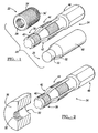
- Figure 1 is a perspective view of a preferred embodiment of a kit for replacing damaged threads of a spark plug hole;
- Figure 2 is a partially cross-sectional perspective view illustrating a spark plug hole with damaged threads of an engine block and the preferred tap of Figure 1;
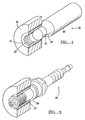
- Figure 3 is a partially cross-sectional perspective view illustrating an intermediate step in a preferred process of the present invention wherein the insert of Figure 1 is being located in the engine block;
- Figure 4 is a partially cross-sectional perspective view similar to Figure 3 with the insert located in the engine block and illustrating the expansion tool of Figure 1;
- Figure 5 is a partially cross-sectional perspective view of repaired spark plug hole utilizing the preferred kit, insert and process illustrated in the preceding drawings;
- Figure 6 is a perspective view of another embodiment of a tap according to the invention; and
- Figure 7 is a perspective view of further embodiment of a tap according to the invention.
-
- The following description of the preferred embodiments is merely exemplary in nature and is in no way intended to limit the invention, its application, or uses. For example, although the invention is discussed throughout with respect to threads for spark plugs, the invention may be useful in many other threaded applications.
- Referring to Figure 1, a preferred embodiment of a kit, generally indicated as 20, according to the present invention is illustrated. The
kit 20 basically includes aninsert 22, atap 24, and an expandingtool 26. As illustrated, theinsert 22 includesthreads 28 located on its inner cylindrical surface. Theseinner threads 28 extend only about one-third of the overall axial length of theinsert 22. Preferably, theseinner threads 28 extend less than about 75 percent of the overall axial length of theinsert 22; more preferably, less than about two-thirds of the overall axial length of theinsert 22; even more preferably, less than about 50 percent of the overall axial length of theinsert 22; and most preferably, less than about one-third the overall axial length of theinsert 22. - These
inner threads 28 correspond to theoriginal threads 32 of thespark plug hole 30, as seen in Figure 2. "Correspond" or "corresponding" as used herein, simply means thethreads 28 are adapted to cooperate with thethreads 32 of the spark plug or other fastening object which was originally intended to be inserted into thehole 30. Thus, theinner threads 28 are not necessarily of the identical axial length as theoriginal threads 32 of thehole 30, although they correspond to theoriginal threads 32 of thespark plug hole 30. Notwithstanding, theinner threads 28 preferably have an axial length which is about the same as the original damagedthreads 32 being replaced; more preferably, have an axial length which is the same or less than theoriginal threads 32; and even more preferably, have an axial length which is substantially identical to theoriginal threads 32. - At least the
inner threads 28 of the insert are preferably made of a material that is harder than the material of theengine block 36. Theinner threads 28 may alternatively be treated or coated to increase their strength. Thus, theinner threads 28 of the insert are less susceptible to damage than the original sparkplug hole threads 32. A particularly preferred material for constructing theinsert 22 is carbon steel. Even when the material of theinsert 22 is different from that of theengine block 36, theinsert 22 preferably has a substantially identical heat expansion and contraction rate. In other words, the expansion and contraction of theinsert 22 due to heat is preferably substantially identical to that of the surroundingengine block 36 material. This helps ensure a good seal is maintained between theinsert 22 and the engine block during extended use. - With continuing reference to Figure 1 and Figure 2, the
insert 22 includesouter threads 34 which preferably encompass the entire overall axial length of the outer surface of theinsert 22, as illustrated. In addition, theouter threads 34 preferably axially extend at least about 1.25 times the axial length of the original, damagedthreads 32; more preferably, at least about 1.6 times the axial length of the original, damagedthreads 32; even more preferably, at least about 2 times the axial length of the original, damagedthreads 32; and most preferably, at least about 3 times the axial length of original, damagedthreads 32. By increasing the axial length of theouter threads 34 to an axial length greater than that of theoriginal threads 32, more gripping force is possible between theinsert 22 and theengine block 36, as indicated hereinafter. - The
outer threads 34 include knurled threads near the distal end of the insert 34'. The knurled threads 34' act as teeth and help imbed theinsert 22 into the inner wall of the expandedhole 30 of theengine block 36, as discussed hereinafter. Consequently, the knurled threads 34' act as a retention mechanism which helps prevent theinsert 22 from rotating out of theengine block 36, after theinsert 22 has been threaded into the enlargedhole 30. - In an alternative retention mechanism that is not illustrated, a flange is provided at the distal or outer axial end of the insert Thus, the flange may operate as a stop to frictionally engage the insert in place. It is highly preferred, however, that the radial outer surface of any such flange would include threads thereon. Thus, the axial length of the threads are preferably maximized to provide threads along the entire axial length of the outer surface of the insert
- The
tap 24 includes a smaller diameter threadedsegment 38 at its distal end. Thethreads 40 of thissegment 38 are adapted to cooperate with the original damagedthreads 32 to help guide and pull thetap 24 into the originalspark plug hole 30. A generally conically shapedreamer segment 42 is adapted to ream out the damagedthreads 32 and thehole 30 to an enlarged diameter. Thisreamer segment 42 transitions to a larger diameterthread milling segment 44. Thethread milling segment 44 is adapted to mill new larger diameter threads for theinsert 22 into theengine block 36 material surrounding thehole 30. Alast nut segment 46 operates as a mechanism to enable rotation of thetap 24 at the forces required. - The
expansion tool 26 is a generally cylindrical member with alarger diameter segment 48, asmaller diameter segment 50, and a generally conically shapedsurface segment 52 therebetween. Thesmaller diameter segment 50 is roughly the diameter of the internal, unthreaded portion of theinsert 22. The conically shapedsegment 52 is adapted to expand theinsert 22 as discussed hereinafter. The distal end of thelarger diameter segment 48 is adapted to receive a blow from a hammer, or other object to exert an axial force on theexpansion tool 26. - Although the
tap 24 andexpansion tool 26 are illustrated herein as two separate and distinct members, the functional features of each may alternatively be provided as a single, integral tool. For example, theexpansion tool 26 may be located across the distal end of thetap 24 with its axis perpendicular to the axis of thetap 24 and be useful as the rotation enabling mechanism of thetap 24. - Referring to Figure 2, an original
spark plug hole 30 in an engine block with damagedthreads 32 is illustrated. In a preferred embodiment of the method as seen in the drawings thetap 24 is inserted into thespark plug hole 30. The outer surfaces of thetap 24 are lubricated, prior to inserting thetap 24 into thehole 30. Thesmaller diameter threads 40 at the distal end of thetap 24 help to initially guide and pull thetap 24 into thehole 30. As thereamer segment 42 of thetap 24 enters thehole 30, the reamer segment enlarges thehole 30. Continuing to rotate thetap 24, themilling segment 44 of thetap 24 passed into thehole 30 and mills threads 54 (seen in Figure 3) into the material of theengine block 36 surrounding the nowenlarged hole 30. All of this is accomplished by the step of simply rotating thetap 24 as it passes into thehole 30. Thus, a single tool, thetap 24, accomplishes both the enlarging of thehole 30 and the milling of thethreads 54 as a single step of rotating thetap 24. - If the damaged
threads 32 are not adequate to pull the tap through thehole 30 , thehole 30 may alternatively be enlarged using a drill rather than thereamer segment 42 of thetap 24. Thetap 24 is then utilized to mill thenew threads 54 in the hole of theengine block 36 using themilling segment 44 as described above. Thus, a first tool - the drill (not seen) - is utilized to enlarge thehole 30 and a second, separate tool - thetap 24 is utilized to mill thethreads 54 in two separate steps. - The larger
diameter milling segment 44 of the tap mills thethreads 54 into the sides of theenlarged hole 30. As can be seen by comparing theengine block 36 fragment of Figure 2 with that of Figure 3, the entire axial length of theenlarged hole 30 of theengine block 36 is preferably milled to havethreads 54. Thus, the gripping force between theinsert 22 and the typically softer material of theengine block 36 can be increased. For example, this increased gripping capacity permits theinsert 22 to resist higher forces created by expanding gasses within the cylinder of theengine block 36 against an insertedspark plug 56. - Referring to Figure 3, the
insert 22 is next threaded into theenlarged hole 30. Preferably, a sealant is coated onto theexternal threads 34 of theinsert 22 to help insure against gases exiting the cylinder between theengine block 36 and theinsert 22. The sealant is preferably, a high temperature RTV silicone. The sealant may, for example, include an adhesive and alternatively operate as the retention mechanism in place of the knurled threads 34'. Thus, a tube of adhesive may alternatively function as a retention mechanism implement of an alternative kit. - The
insert 22 is threaded into thehole 30 so that the knurled threads 34' of theinsert 22 are at the outer axial side of thehole 30. Aspark plug 56 may be threaded onto theinternal threads 28 of theinsert 22 to help thread theexternal threads 34 of theinsert 22 onto thethreads 54 of theenlarged hole 30. The top of theinsert 22 is preferably threaded into theenlarged hole 30 until its outer end is flush with the surroundingengine block 36. - Referring to Figure 4, the
smaller diameter segment 50 of theexpansion tool 26 is placed into theinsert 22 without turning. The relatively close fit between the outer diameter of thesmaller segment 50 and the inner unthreaded portion of theinsert 22 appropriately aligns the generally conically shapedsurface segment 52 with theinsert 22. An object (not shown), such as a hammer, is impacted onto the distal end of theexpansion tool 26. This drives the knurled threads 34' of theinsert 22 into theengine block 36 and provides a retention mechanism which helps prevent theinsert 22 from thereafter rotating out of theengine block 36. The geometry of the conical shapedsegment 52 of theexpansion tool 26 creates a sealing surface between theinsert 22 and thespark plug 56. In any case, after use of theexpansion tool 26 the top end surface of theinsert 22 is preferably configured to seal via compression with the sealingsurface 58 of thespark plug 56. Thus, theexpansion tool 26 acts as a retention mechanism implement of thekit 20. - Alternative preferred a
taps taps taps torque segment taps torque segment tap tap - Referring to Figure 6, a first alternative
preferred tap 124 is illustrated. Thetap 124 has atorque segment 146 which includes arecess 147. Therecess 147 is adapted to receive a socket wrench, for example, via anextension member 149. The socket wrench andextension 149 are preferably not part of the kit, but are instead supplied by the user. Such anextension member 149 would fit into therecess 147 and engage therewith. Thus, torque generated by the socket wrench would be transmitted to thetap 124 by the cooperation between the socket wrench and therecess 147. Furthermore, it can be understood that the cooperation between the socket wrench and thetap 124 occurs fully within the outer radial dimension of thetap 124. Consequently, the engagement of the socket wrench with thetap 124 occurs fully within the outer radial dimension of thetap 124. - Referring to Figure 7, another alternative
preferred tap 224 is illustrated. Thetap 224 has atorque segment 246 which includes anut segment 247. Thisnut segment 247 is dimension to be smaller than the maximum radial dimension, or diameter, of thetap 246. In addition,segment 249 is preferably of a diameter which is substantially equal to or less than the outermost diameter of themilling thread segment 44. An appropriatelysized socket 249 of a socket wrench is adapted to engagenut segment 247 and to transmit torque to thetap 224. Again, the socket wrench andsocket 249 are preferably not part of the kit, but are instead supplied by the user. - The outer diameter of the appropriately
sized socket 249 is preferably substantially equal to or less than the maximum diameter of thetap 224. More preferably, the outer diameter of the appropriatelysized socket 249 is equal to or less than the maximum diameter of thetap 224. Consequently, in such a preferred execution as illustrated the cooperating elements between the torque generating tool and thetap 224 enable engagement while remaining fully within the maximum outer radial dimensions of thetap 224. - Only a small number of the many possible alternatives are described above. Many additional modifications and alternatives beyond those described above, however, may be made without departing from the spirit and scope of the inventions disclosed above. For example, the insert may alternatively be comprised of annular segments of varying diameters connected together, rather than the illustrated single diameter annular segment. Thus, the tap, would be appropriately redesigned.
- The description of the invention is merely exemplary in nature and, thus, variations that do not depart from the gist of the invention are intended to be within the scope of the invention. Such variations are not to be regarded as a departure from the spirit and scope of the invention. Thus, the invention encompasses all modifications within the scope of the appended claims.
Claims (35)
- An insert useful for replacing damaged threads in a hole, the insert comprising:an inner surface having inner threads corresponding to the damaged threads being replaced; andan outer surface having outer threads extending a length that is greater than the originally extending length of the damaged threads.
- An insert according to Claim 1, further comprising knurled threads on the outer surface of the insert.
- An insert according to any one of the previous claims, wherein the length of the outer threads is at least about 1.5 times greater than the length of the damaged threads.
- An insert according to any one of the previous claims, wherein the inner threads are harder than the damaged threads being replaced.
- An insert according to any one of the previous claims, wherein the inner threads are about the same length as the length of the damaged threads.
- An insert according to any one of the previous claims, further comprising a sealing surface located at the distal end of the insert and adapted to form a compression seal against a cooperating surface of a spark plug.
- A kit useful for replacing damaged threads in a hole, the kit comprising:an insert having an inner cylindrical surface and an outer cylindrical surface, the inner cylindrical surface having inner threads corresponding to the damaged threads being replaced, the outer surface having outer threads extending a distance greater than that of the threads being replaced;a tap having a thread milling segment adapted to mill threads to cooperate with the outer threads; anda retention mechanism implement.
- A kit according to Claim 7, wherein the tap further comprises, a guiding thread adapted to cooperate with the damaged threads being replaced, and a reaming segment between the guiding thread and the thread milling segment.
- A kit according to Claim 7 or 8, wherein the insert further comprises knurled threads at one end thereof and wherein the retention mechanism implement is an expansion tool adapted to imbed the knurled threads into a material surrounding the hole.
- A kit according to any one of the previous Claim 7 to 9, wherein the axial length of the outer threads of the insert is at least about 1.5 times greater than the length of the damaged threads.
- A kit according to any one of the previous Claims 7 to 10, wherein the inner threads of the insert are harder than the damaged threads being replaced.
- A kit according to any one of the previous Claims 7 to 11, wherein the inner threads of the insert are about the same axial length as the originally extending axial length of the damaged threads.
- An kit according to any one of the previous Claims 7 to 12, wherein the insert further comprises a sealing surface located at the distal end of the insert and adapted to form a compression seal against a cooperating surface of a spark plug.
- A method for replacing damaged threads in a hole, the method comprising the steps of:enlarging the diameter of the hole;milling threads along the enlarged hole over a length greater than the length of the threads being replaced;threading an insert having outer threads along a length greater than the original threaded segment and having inner threads corresponding to the original threaded segment into the enlarged hole on the milled threads; andthereafter fixing the insert against rotation.
- A method according to Claim 14, further comprising the step of threading a spark plug onto the inner threads of the insert
- A method according to Claim 14, wherein the step of threading the spark plug further comprises sealing the spark plug against an end of the insert
- A method according to any one of the previous Claims 14 to 16, wherein the steps of enlarging the diameter of the hole and milling threads along the enlarged hole are accomplished utilizing a single step tool having a reamer segment and a thread milling segment.
- A method according to any one of the previous Claims 14 to 17, wherein the step of fixing the insert against rotation further comprises pushing knurled threads of the insert into a material surrounding the hole.
- A method according to any one of the previous Claims 14 to 18, further comprising the step of applying a sealant between the outer threads of the insert and a material surrounding the enlarged hole.
- A kit useful for replacing damaged threads and a hole, the kit comprising:an insert having an inner cylindrical surface and outer cylindrical surface, the inner cylindrical surface having inner threads corresponding to the damaged threads being replaced, the outer surface having outer threads; anda tap having a thread milling segment adapted to mill threads to cooperate with the outer threads, the tap further having a torque segment adapted to enable engagement of a torque generating tool with the tap while any engagement mechanisms of the torque generating tool remain substantially within an outer radial dimension of the tap.
- A kit according to Claim 20, wherein the torque generating tool is not a part of the kit.
- A kit according to Claim 20 or 21, wherein the torque segment includes a recess adapted to enable engagement with the torque generating tool and wherein the torque generating tool comprises a socket wrench.
- A kit according to any one of the previous Claims 20 to 22, wherein the torque segment includes a nut segment adapted to enable engagement with the torque generating tool and wherein the torque generating tool comprises a socket.
- A kit according to any one of the previous Claims 20 to 23, further comprising a retention mechanism implement.
- A kit according to any one of the previous Claims 20 to 24, wherein any engagement mechanisms of the torque generating tool remain substantially within the outer radial dimensions of the tap along substantially an entire length of the tap.
- A kit according to any one of the previous Claims 20 to 25, wherein any engagement mechanisms of the torque generating tool remain within the outer radial dimensions of the tap.
- A kit according to any one of the previous Claims 20 to 26, wherein one of the outer radial dimension of the tap and an outer radial dimension of the torque generating tool is defined by an outer circumferential wall.
- A kit according to any one of the previous Claims 20 to 27, wherein one of the maximum outer radial dimension of the tap and an outer radial dimension of the torque generating tool is defined by an outer diameter of a cylindrical segment thereof
- A kit useful for replacing damaged threads and a hole, the kit comprising:an insert having an inner cylindrical surface and outer cylindrical surface, the inner cylindrical surface having inner threads corresponding to the damaged threads being replaced, the outer surface having outer threads; anda tap having a thread milling segment adapted to mill threads to cooperate with the outer threads, the tap further having a torque engagement mechanism adapted to engage a cooperating engagement mechanism of a torque generating tool, the engagement mechanisms having a maximum radial dimension that is substantially equal to or less than a maximum radial dimension of the tap.
- A kit according to Claim 29, wherein the torque generating tool is not a part of the kit.
- A kit according to Claim 29 or 30, wherein the torque engagement mechanism has a recess adapted to enable engagement with the torque generating tool and wherein the torque generating tool comprises a socket wrench.
- A kit according to any one of the previous Claims 29 to 31, wherein the torque engagement mechanism has a nut segment adapted to enable engagement with the torque generating tool and wherein the torque generating tool comprises a socket.
- A kit according to any one of the previous Claims 29 to 32, further comprising a retention mechanism implement.
- A kit according to any one of the Claims 29 to 33, wherein the engagement mechanisms have a maximum radial dimension that is substantially equal to or less than a maximum radial dimension of the tap along substantially an entire length of the tap.
- A kit according to any one of the previous Claims 29 to 34, wherein the cooperating engagement mechanism of the torque generating tool has a maximum radial dimension that is equal to or less than a maximum radial dimension of the tap.
Applications Claiming Priority (2)
| Application Number | Priority Date | Filing Date | Title |
|---|---|---|---|
| US151196 | 2002-05-20 | ||
| US10/151,196 US20030215296A1 (en) | 2002-05-20 | 2002-05-20 | Method, kit and insert for replacing damaged threads |
Publications (1)
| Publication Number | Publication Date |
|---|---|
| EP1364736A1 true EP1364736A1 (en) | 2003-11-26 |
Family
ID=29400501
Family Applications (1)
| Application Number | Title | Priority Date | Filing Date |
|---|---|---|---|
| EP03010346A Withdrawn EP1364736A1 (en) | 2002-05-20 | 2003-05-08 | Method, kit and insert for replacing damaged threads |
Country Status (3)
| Country | Link |
|---|---|
| US (1) | US20030215296A1 (en) |
| EP (1) | EP1364736A1 (en) |
| JP (1) | JP2004003475A (en) |
Cited By (1)
| Publication number | Priority date | Publication date | Assignee | Title |
|---|---|---|---|---|
| WO2013142985A1 (en) * | 2012-03-27 | 2013-10-03 | Speedtap Industries Inc. | A tapping device and method of use |
Families Citing this family (13)
| Publication number | Priority date | Publication date | Assignee | Title |
|---|---|---|---|---|
| US7438324B2 (en) * | 2003-06-30 | 2008-10-21 | Keiper Michael C | Method and components for repairing broken conduit extending from concrete foundations |
| JP4644448B2 (en) * | 2004-07-09 | 2011-03-02 | 濱中ナット株式会社 | Tap |
| JP5235123B2 (en) * | 2008-10-23 | 2013-07-10 | 株式会社湘南合成樹脂製作所 | Segment connection method and connector |
| US20130068988A1 (en) * | 2011-09-19 | 2013-03-21 | Roger Kliskey | Valve stem repair kit and method |
| US8955535B2 (en) * | 2011-09-19 | 2015-02-17 | Summit Tool Company | Valve stem repair kit and method |
| JP6523043B2 (en) * | 2015-05-28 | 2019-05-29 | 株式会社大岡製作所 | Tap |
| US11466800B2 (en) * | 2015-12-09 | 2022-10-11 | Certus Energy Solutions, Llc | Tubular coupling |
| US10857641B2 (en) | 2017-08-18 | 2020-12-08 | Rolls-Royce Corporation | Tool for facilitating the machining of recessed inserts |
| USD876213S1 (en) | 2018-01-15 | 2020-02-25 | Fidel Ramirez | Insertion tool for spark plug ports and other tubular objects |
| CN111469095A (en) * | 2020-05-22 | 2020-07-31 | 安徽全柴动力股份有限公司 | Engine bowl-shaped plug dismounting device |
| CN113894371B (en) * | 2021-11-01 | 2023-06-27 | 中国商用飞机有限责任公司 | Screw tap device for repairing internal threads |
| CN116275860B (en) * | 2023-01-17 | 2025-08-19 | 重庆金康动力新能源有限公司 | Reworking method for position deviation of positioning pin hole |
| CN116638258A (en) * | 2023-03-31 | 2023-08-25 | 中铁隧道局集团有限公司 | Repair process of inner thread of super-large diameter shield cutter head under normal pressure tool changer and cutter barrel mounting seat |
Citations (4)
| Publication number | Priority date | Publication date | Assignee | Title |
|---|---|---|---|---|
| US3254690A (en) * | 1964-10-08 | 1966-06-07 | Neuschotz Robert | Methods and apparatus for locking threaded elements and the product produced thereby |
| US3568230A (en) * | 1966-03-15 | 1971-03-09 | Rosan Eng Corp | Method of making an insert with expandable head for locking in noncounterbored bores |
| US3750259A (en) * | 1970-12-14 | 1973-08-07 | T Timmons | Method and apparatus for repairing threads of a through bore by installing a threaded sleeve |
| DE10039450A1 (en) * | 2000-08-11 | 2002-02-28 | Boellhoff Gmbh | Renovation of screw connection with damaged thread comprises using self-tapping drill to drill out damaged thread and simultaneously cut new thread, bolt inserted into bush with internal and external thread then being screwed into new bore |
Family Cites Families (10)
| Publication number | Priority date | Publication date | Assignee | Title |
|---|---|---|---|---|
| US1475561A (en) * | 1921-04-27 | 1923-11-27 | Bath | Combined reamer and tap |
| US2984279A (en) * | 1958-08-07 | 1961-05-16 | Rosan Eng Corp | Locking insert with deformable flange bearing peripheral biting teeth |
| GB972814A (en) * | 1960-07-25 | 1964-10-14 | Rosan Eng Corp | Thin-walled inserts |
| US3081808A (en) * | 1960-07-25 | 1963-03-19 | Rosan Eng Corp | Thin-walled inserts and method of making same |
| US3604105A (en) * | 1969-05-16 | 1971-09-14 | Fridair Ind | Seal assembly for threaded parts and method |
| US3694838A (en) * | 1970-09-02 | 1972-10-03 | Phillips Screw Co | Apparatus for renewing damaged spark plug ports |
| US3864806A (en) * | 1971-11-08 | 1975-02-11 | Le Roy P Hanson | Method of repairing stripped spark plug threads in engine heads |
| US3847499A (en) * | 1973-09-04 | 1974-11-12 | Tridair Industries | Tool and method for reaming and tapping a spark plug opening in a rotary engine housing |
| US5037251A (en) * | 1989-03-24 | 1991-08-06 | Roth Alfred C | Thread tap |
| US6474285B2 (en) * | 2001-02-23 | 2002-11-05 | Tansil L. Phillips | Method of repairing a damaged spark plug hole |
-
2002
- 2002-05-20 US US10/151,196 patent/US20030215296A1/en not_active Abandoned
-
2003
- 2003-05-08 EP EP03010346A patent/EP1364736A1/en not_active Withdrawn
- 2003-05-12 JP JP2003133146A patent/JP2004003475A/en active Pending
Patent Citations (4)
| Publication number | Priority date | Publication date | Assignee | Title |
|---|---|---|---|---|
| US3254690A (en) * | 1964-10-08 | 1966-06-07 | Neuschotz Robert | Methods and apparatus for locking threaded elements and the product produced thereby |
| US3568230A (en) * | 1966-03-15 | 1971-03-09 | Rosan Eng Corp | Method of making an insert with expandable head for locking in noncounterbored bores |
| US3750259A (en) * | 1970-12-14 | 1973-08-07 | T Timmons | Method and apparatus for repairing threads of a through bore by installing a threaded sleeve |
| DE10039450A1 (en) * | 2000-08-11 | 2002-02-28 | Boellhoff Gmbh | Renovation of screw connection with damaged thread comprises using self-tapping drill to drill out damaged thread and simultaneously cut new thread, bolt inserted into bush with internal and external thread then being screwed into new bore |
Cited By (2)
| Publication number | Priority date | Publication date | Assignee | Title |
|---|---|---|---|---|
| WO2013142985A1 (en) * | 2012-03-27 | 2013-10-03 | Speedtap Industries Inc. | A tapping device and method of use |
| CN104271298A (en) * | 2012-03-27 | 2015-01-07 | 斯皮塔普工业股份有限公司 | A tapping device and method of use |
Also Published As
| Publication number | Publication date |
|---|---|
| JP2004003475A (en) | 2004-01-08 |
| US20030215296A1 (en) | 2003-11-20 |
Similar Documents
| Publication | Publication Date | Title |
|---|---|---|
| US20030215296A1 (en) | Method, kit and insert for replacing damaged threads | |
| US7823262B2 (en) | Method of replacing a nut plate fastener assembly | |
| US8186031B2 (en) | Bushing replacement kit | |
| US6530731B2 (en) | Self-tapping insert, insert assembly, and method for mounting the insert | |
| CN101542181B (en) | Sealing plug for blind installation | |
| US8661637B2 (en) | Sealing plug removal apparatus | |
| CN101652211B (en) | Tool with replaceable tip | |
| US20090110509A1 (en) | Self-tapping insert and method of utilizing the same to replace damaged bores and threads | |
| CA2411984C (en) | Thread replacement system and device | |
| US3750259A (en) | Method and apparatus for repairing threads of a through bore by installing a threaded sleeve | |
| CA2499555A1 (en) | Split lock screw fastener assembly and method | |
| IE49745B1 (en) | Combination hole-drilling and fastener-driving tools | |
| JP2004504547A5 (en) | ||
| US3694838A (en) | Apparatus for renewing damaged spark plug ports | |
| US6447227B1 (en) | Threaded fastener | |
| EP1691087A2 (en) | Frangible Blind Rivet | |
| US7484281B2 (en) | Tool system for replacing a glow plug of a diesel engine | |
| US7191504B1 (en) | Universal bushing tool and method of use | |
| US20100329814A1 (en) | Self-Tapping Insert and Method of Utilizing the Same to Replace Damaged Bores and Threads | |
| JP4590279B2 (en) | Repair method of female thread using a tapping tap | |
| GB1604504A (en) | Blind fastener | |
| JPH01503128A (en) | thread cutting tool | |
| US6474285B2 (en) | Method of repairing a damaged spark plug hole | |
| US20100329816A1 (en) | Self-Tapping Insert and Method of Utilizing the Same to Replace Damaged Threads for Hydraulic and Pneumatic Applications | |
| US8544366B2 (en) | Spark plug removal tool apparatus |
Legal Events
| Date | Code | Title | Description |
|---|---|---|---|
| PUAI | Public reference made under article 153(3) epc to a published international application that has entered the european phase |
Free format text: ORIGINAL CODE: 0009012 |
|
| AK | Designated contracting states |
Kind code of ref document: A1 Designated state(s): AT BE BG CH CY CZ DE DK EE ES FI FR GB GR HU IE IT LI LU MC NL PT RO SE SI SK TR |
|
| AX | Request for extension of the european patent |
Extension state: AL LT LV MK |
|
| RAP1 | Party data changed (applicant data changed or rights of an application transferred) |
Owner name: NEWFREY LLC |
|
| 17P | Request for examination filed |
Effective date: 20040521 |
|
| AKX | Designation fees paid |
Designated state(s): AT BE BG CH CY CZ DE DK EE ES FI FR GB GR HU IE IT LI LU MC NL PT RO SE SI SK TR |
|
| 17Q | First examination report despatched |
Effective date: 20040812 |
|
| STAA | Information on the status of an ep patent application or granted ep patent |
Free format text: STATUS: THE APPLICATION IS DEEMED TO BE WITHDRAWN |
|
| 18D | Application deemed to be withdrawn |
Effective date: 20061201 |