EP1364523B1 - SIP Proxy Server which supports double registration in a bearer provider network and a service provider network - Google Patents
SIP Proxy Server which supports double registration in a bearer provider network and a service provider network Download PDFInfo
- Publication number
- EP1364523B1 EP1364523B1 EP02727325.9A EP02727325A EP1364523B1 EP 1364523 B1 EP1364523 B1 EP 1364523B1 EP 02727325 A EP02727325 A EP 02727325A EP 1364523 B1 EP1364523 B1 EP 1364523B1
- Authority
- EP
- European Patent Office
- Prior art keywords
- control protocol
- ipsa
- sip
- network
- protocol message
- Prior art date
- Legal status (The legal status is an assumption and is not a legal conclusion. Google has not performed a legal analysis and makes no representation as to the accuracy of the status listed.)
- Expired - Lifetime
Links
- 241001610351 Ipsa Species 0.000 claims description 41
- 230000000977 initiatory effect Effects 0.000 claims description 37
- 238000000034 method Methods 0.000 claims description 18
- 238000004590 computer program Methods 0.000 claims description 5
- 238000010586 diagram Methods 0.000 description 8
- 238000004891 communication Methods 0.000 description 5
- 230000011664 signaling Effects 0.000 description 3
- 238000001514 detection method Methods 0.000 description 2
- 238000004458 analytical method Methods 0.000 description 1
- 230000001419 dependent effect Effects 0.000 description 1
- 238000012986 modification Methods 0.000 description 1
- 230000004048 modification Effects 0.000 description 1
- 238000000926 separation method Methods 0.000 description 1
Images
Classifications
-
- H—ELECTRICITY
- H04—ELECTRIC COMMUNICATION TECHNIQUE
- H04L—TRANSMISSION OF DIGITAL INFORMATION, e.g. TELEGRAPHIC COMMUNICATION
- H04L69/00—Network arrangements, protocols or services independent of the application payload and not provided for in the other groups of this subclass
-
- H—ELECTRICITY
- H04—ELECTRIC COMMUNICATION TECHNIQUE
- H04L—TRANSMISSION OF DIGITAL INFORMATION, e.g. TELEGRAPHIC COMMUNICATION
- H04L65/00—Network arrangements, protocols or services for supporting real-time applications in data packet communication
- H04L65/10—Architectures or entities
- H04L65/102—Gateways
- H04L65/1043—Gateway controllers, e.g. media gateway control protocol [MGCP] controllers
-
- H—ELECTRICITY
- H04—ELECTRIC COMMUNICATION TECHNIQUE
- H04L—TRANSMISSION OF DIGITAL INFORMATION, e.g. TELEGRAPHIC COMMUNICATION
- H04L65/00—Network arrangements, protocols or services for supporting real-time applications in data packet communication
- H04L65/1066—Session management
- H04L65/1101—Session protocols
-
- H—ELECTRICITY
- H04—ELECTRIC COMMUNICATION TECHNIQUE
- H04L—TRANSMISSION OF DIGITAL INFORMATION, e.g. TELEGRAPHIC COMMUNICATION
- H04L65/00—Network arrangements, protocols or services for supporting real-time applications in data packet communication
- H04L65/1066—Session management
- H04L65/1101—Session protocols
- H04L65/1104—Session initiation protocol [SIP]
-
- H—ELECTRICITY
- H04—ELECTRIC COMMUNICATION TECHNIQUE
- H04M—TELEPHONIC COMMUNICATION
- H04M3/00—Automatic or semi-automatic exchanges
- H04M3/42—Systems providing special services or facilities to subscribers
-
- H—ELECTRICITY
- H04—ELECTRIC COMMUNICATION TECHNIQUE
- H04M—TELEPHONIC COMMUNICATION
- H04M7/00—Arrangements for interconnection between switching centres
- H04M7/006—Networks other than PSTN/ISDN providing telephone service, e.g. Voice over Internet Protocol (VoIP), including next generation networks with a packet-switched transport layer
-
- H—ELECTRICITY
- H04—ELECTRIC COMMUNICATION TECHNIQUE
- H04Q—SELECTING
- H04Q3/00—Selecting arrangements
- H04Q3/0016—Arrangements providing connection between exchanges
- H04Q3/0029—Provisions for intelligent networking
-
- H—ELECTRICITY
- H04—ELECTRIC COMMUNICATION TECHNIQUE
- H04L—TRANSMISSION OF DIGITAL INFORMATION, e.g. TELEGRAPHIC COMMUNICATION
- H04L41/00—Arrangements for maintenance, administration or management of data switching networks, e.g. of packet switching networks
- H04L41/50—Network service management, e.g. ensuring proper service fulfilment according to agreements
- H04L41/5061—Network service management, e.g. ensuring proper service fulfilment according to agreements characterised by the interaction between service providers and their network customers, e.g. customer relationship management
- H04L41/507—Filtering out customers affected by service problems
-
- H—ELECTRICITY
- H04—ELECTRIC COMMUNICATION TECHNIQUE
- H04L—TRANSMISSION OF DIGITAL INFORMATION, e.g. TELEGRAPHIC COMMUNICATION
- H04L41/00—Arrangements for maintenance, administration or management of data switching networks, e.g. of packet switching networks
- H04L41/50—Network service management, e.g. ensuring proper service fulfilment according to agreements
- H04L41/508—Network service management, e.g. ensuring proper service fulfilment according to agreements based on type of value added network service under agreement
- H04L41/5087—Network service management, e.g. ensuring proper service fulfilment according to agreements based on type of value added network service under agreement wherein the managed service relates to voice services
-
- H—ELECTRICITY
- H04—ELECTRIC COMMUNICATION TECHNIQUE
- H04M—TELEPHONIC COMMUNICATION
- H04M3/00—Automatic or semi-automatic exchanges
- H04M3/42—Systems providing special services or facilities to subscribers
- H04M3/42136—Administration or customisation of services
- H04M3/42153—Administration or customisation of services by subscriber
-
- H—ELECTRICITY
- H04—ELECTRIC COMMUNICATION TECHNIQUE
- H04M—TELEPHONIC COMMUNICATION
- H04M3/00—Automatic or semi-automatic exchanges
- H04M3/42—Systems providing special services or facilities to subscribers
- H04M3/54—Arrangements for diverting calls for one subscriber to another predetermined subscriber
-
- H—ELECTRICITY
- H04—ELECTRIC COMMUNICATION TECHNIQUE
- H04Q—SELECTING
- H04Q2213/00—Indexing scheme relating to selecting arrangements in general and for multiplex systems
- H04Q2213/13034—A/D conversion, code compression/expansion
-
- H—ELECTRICITY
- H04—ELECTRIC COMMUNICATION TECHNIQUE
- H04Q—SELECTING
- H04Q2213/00—Indexing scheme relating to selecting arrangements in general and for multiplex systems
- H04Q2213/13091—CLI, identification of calling line
-
- H—ELECTRICITY
- H04—ELECTRIC COMMUNICATION TECHNIQUE
- H04Q—SELECTING
- H04Q2213/00—Indexing scheme relating to selecting arrangements in general and for multiplex systems
- H04Q2213/13196—Connection circuit/link/trunk/junction, bridge, router, gateway
-
- H—ELECTRICITY
- H04—ELECTRIC COMMUNICATION TECHNIQUE
- H04Q—SELECTING
- H04Q2213/00—Indexing scheme relating to selecting arrangements in general and for multiplex systems
- H04Q2213/13204—Protocols
-
- H—ELECTRICITY
- H04—ELECTRIC COMMUNICATION TECHNIQUE
- H04Q—SELECTING
- H04Q2213/00—Indexing scheme relating to selecting arrangements in general and for multiplex systems
- H04Q2213/13339—Ciphering, encryption, security
-
- H—ELECTRICITY
- H04—ELECTRIC COMMUNICATION TECHNIQUE
- H04Q—SELECTING
- H04Q2213/00—Indexing scheme relating to selecting arrangements in general and for multiplex systems
- H04Q2213/13348—Channel/line reservation
-
- H—ELECTRICITY
- H04—ELECTRIC COMMUNICATION TECHNIQUE
- H04Q—SELECTING
- H04Q2213/00—Indexing scheme relating to selecting arrangements in general and for multiplex systems
- H04Q2213/13389—LAN, internet
Definitions
- the present invention relates to an IP (Internet Protocol) based service architecture (IPSA).
- IP Internet Protocol
- IIPSA Internet Protocol based service architecture
- a telephony service provider today provides all the end-user supplementary telephony services.
- An end-user with multiple telephone subscriptions must configure the supplementary services associated with each subscription separately even though many of the services are the same, such as the service "Call forwarding if no answer”.
- the WO 00/79756 discloses a method of providing a Value-Added Service (VAS) in a telecommunications network operable with Session Initiation Protocol (SIP).
- the telecommunications network includes a SIPext SSP server, a trigger server, and a service node supporting VAS that is operable with Intelligent Network Application Protocol (INAP).
- INP Intelligent Network Application Protocol
- the SIPext SSP server Before processing a call (originating or terminating) between two users, which is effectuated by receiving a request message in the SIPext SSP server, the SIPext SSP server consults a user profile stored in the trigger server when a message for a user subscribed with a service provider arrives thereat. While processing the call, upon encountering an armed detection point for the subscribed service, a SIP register request is formulated by the SIPext SSP server based on the user profile obtained from the trigger server.
- a service provider network (IP network) and a telephony provider network (IPT provider network) are separated in an IPT (IP Telephony) environment.
- IP network IP network
- IPT provider network IP Telephony
- This separation allows an end-user to have the same services across multiple subscription networks.
- an end-user has to customize just one set of services and apply them all to his telephony subscriptions.
- This allows the end-user to manage his services in a centralized manner instead of customize each set of services individually with each telephony provider.
- the IP network is called IPSA network and the functions of the IPT provider network are implemented in a so called SIP network.
- SIP calls can be flexibly routed when the IPSA network is involved, wherein the IPSA network does not require any a priori knowledge of a SIP proxy address. In other words, there is no requirement of an a priori agreement between the SIP call/routing control network and the IPSA network.
- the idea of the present invention is to separate a service provider network from a bearer provider network in an IPT (Internet Protocol Telephony) environment.
- IPT Internet Protocol Telephony
- this concept is realized by using SIP (Session Initiation Protocol) as a control protocol between an IP network called IPSA (IP based Services Architecture) network, an IPT provider network called SIP network and an end-user terminal (user equipment).
- SIP Session Initiation Protocol
- a SIP client represents an end-user's terminal attaching to the communication system using SIP methods.
- the end-user's terminal may be called user equipment (UE) and, for example, may be a PC (Personal Computer) or laptop running an IPT SIP client application.
- UE user equipment
- PC Personal Computer
- a SIP proxy server is part of the SIP network that provides bearer connection and call related functions like call routing capabilities to the end-user.
- an SDB Subscriber Database
- subscriber subscription information such as authentication data and IPSA-ID (IPSA-Identifier).
- IPSA-ID IPSA-Identifier
- the IPSA network shown in Fig. 1 is an IP based service architecture platform that offers services like telephony and other IP type of services to the end-user.
- a user has a unique identity called IPSA-ID within one IPSA cloud.
- the ID may be formed out of the user name and IPSA provider's domain name as ipsa-user@ipsa-provider.com.
- An IP cloud shown in Fig. 1 represents an IP backbone network to interconnect the SIP client, SIP network and IPSA network.
- Figs. 2 and 3 illustrate a registration of a SIP client to the communication system, and in particular to the IPSA network shown in Fig. 1 .
- IPSA IP Security
- Fig. 2 shows a first way of registering an end-user to the IPSA network.
- the SDB contains an IPSA-ID in the form of a logical name at some domain, for example "john.doe@some.ipsa.com".
- the SIP proxy server registers the SIP client to the SIP network and also fetches an IPSA-ID for the end-user represented by the SIP client from the SDB. If an IPSA-ID in the SDB is associated with the end-user, the SIP proxy server generates another REGISTER message with the IPSA-ID and sends it towards the IPSA network. On the basis of this register message, the IPSA network is able to register the SIP client.
- Fig. 3 shows another possibility of registering an end-user to the IPSA network.
- the SIP client directly registers to the IPSA network using its IPSA-ID in another REGISTER message.
- Option 1 shown in Fig. 2 allows the IPT provider to retain the control of which IPSA provider is providing the end-user's services, while option 2 shown in Fig. 3 gives total control to the user with respect to the choice of the IPSA provider.
- FIG. 4 shows a first method of invoking IPSA on the basis of an originating call.
- a SIP client sends an INVITE message towards the SIP network, which message is received by a SIP proxy server.
- the SIP proxy server can route this end-user initiated call towards the IPSA network when an IPSA-ID found in the SDB is associated with the called party B, i.e. with the request URI (Uniform Resource Identifier) B in the INVITE message.
- URI Uniform Resource Identifier
- the SIP client can also send the INVITE message directly to the IPSA network via the SIP proxy server by indicating the request URI with an IPSA-ID of the called party.
- the SIP proxy server then analyses the request URI and forwards the INVITE message to the IPSA network.
- Fig. 6 shows a first method of invoking IPSA on the basis of a terminating call.
- a SIP proxy server receives an INVITE message from an originated endpoint inviting a SIP client called b_party to a call, it fetches an IPSA-ID for the called b_party from the SDB. If an IPSA-ID is associated with the called b_party, the SIP proxy server routes the INVITE message to the IPSA network, using the fetched IPSA-ID along with a new SIP header indicating that this is a terminating call.
- the SIP proxy server further includes a Gateway SIP proxy address or hop address in the routed INVITE message, which will be described in greater detail in connection with Fig. 8 .
- the IPSA network should use this address for further routing.
- the IPSA network then executes any terminating services, and if further routing is needed, it uses the address provided by the SIP proxy server to reach the end-user, i.e. the b_party.
- the INVITE message received by the SIP proxy server already contains the IPSA-ID in the request URI as well as the terminated call indication.
- the SIP proxy server After having analyzed the request URI, the SIP proxy server adds the hop address for further routing to the INVITE message and forwards it to the IPSA network.
- FIG. 8 a mechanism for appropriately routing service invocations between the IPSA network and the SIP network is described.
- the IPSA network may have, as part of service execution, to re-route the SIP call or initiate a new SIP signaling, e.g. call setup, INFO methods, etc., through the SIP network.
- a new SIP signaling e.g. call setup, INFO methods, etc.
- the SIP signaling cannot be sent back to the element in the SIP network that routed the call to the IPSA network and the IPSA network does not necessarily know the topology of the SIP network.
- the SIP network When a SIP proxy server in the SIP network routes a SIP call to the IPSA network, the SIP network provides an address of a SIP proxy in the SIP network to be used as a gateway for SIP signaling which the IPSA network needs to exchange with the SIP network.
- a SIP client sends an INVITE message to the SIP network for inviting another SIP client (b_party).
- the INVITE message is received by a SIP proxy server via a network of SIP proxies forwarding the message.
- the SIP proxy server routes the INVITE message towards the IPSA network and indicates a gateway SIP proxy address in the message.
- an IPSA network element receiving the message knows to which SIP proxy server in the SIP network the call has to be routed in order to reach the b_party.
- the IPSA network element routes the INVITE message to the gateway SIP proxy, the address of which has been indicated by the SIP proxy server.
- the b_party receives the INVITE message from the gateway SIP proxy via the network of SIP proxies.
- the provision of the gateway address to the IPSA network can be implemented by adding a parameter in an SDP (Session Description Protocol) descriptor contained in the SIP message routed from the SIP proxy server to the IPSA network and containing the address of the gateway SIP proxy.
- SDP Session Description Protocol
- the address can be indicated to the IPSA network by adding a SIP header to the SIP message routed from the SIP proxy server to the IPSA network and containing the address of the gateway SIP proxy.
Landscapes
- Engineering & Computer Science (AREA)
- Computer Networks & Wireless Communication (AREA)
- Signal Processing (AREA)
- Multimedia (AREA)
- Business, Economics & Management (AREA)
- General Business, Economics & Management (AREA)
- Computer Security & Cryptography (AREA)
- Data Exchanges In Wide-Area Networks (AREA)
- Telephonic Communication Services (AREA)
Description
- The present invention relates to an IP (Internet Protocol) based service architecture (IPSA).
- A telephony service provider today provides all the end-user supplementary telephony services. An end-user with multiple telephone subscriptions must configure the supplementary services associated with each subscription separately even though many of the services are the same, such as the service "Call forwarding if no answer".
- The
WO 00/79756 - It is an object of the present invention to avoid the necessity of configuring services for each subscription.
- This object is achieved by a SIP proxy server according to
claim 1, a method used in a SIP proxy server according to claim 12, and a computer program product according to claim 23. Further features of the present invention are defined in the dependent claims. - According to the present invention, a service provider network (IP network) and a telephony provider network (IPT provider network) are separated in an IPT (IP Telephony) environment. This separation allows an end-user to have the same services across multiple subscription networks. In other words, with this architecture, an end-user has to customize just one set of services and apply them all to his telephony subscriptions. This allows the end-user to manage his services in a centralized manner instead of customize each set of services individually with each telephony provider.
- According to preferred embodiments of the present invention, the IP network is called IPSA network and the functions of the IPT provider network are implemented in a so called SIP network. In this communication system, SIP calls can be flexibly routed when the IPSA network is involved, wherein the IPSA network does not require any a priori knowledge of a SIP proxy address. In other words, there is no requirement of an a priori agreement between the SIP call/routing control network and the IPSA network.
- In the following the present invention will be described by way of preferred embodiments thereof with reference to the accompanying drawings.
-
-
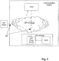
Fig. 1 shows a diagram illustrating functional elements involved in service triggering and control in a communication system according to an embodiment of the present invention. -
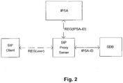
Fig. 2 shows a diagram illustrating a registration to an IPSA network according to an embodiment of the present invention. -
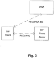
Fig. 3 shows a diagram illustrating a registration to an IPSA network according to another embodiment of the present invention. -
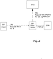
Fig. 4 shows a diagram illustrating an IPSA invocation on the basis of an originating call according to an embodiment of the present invention. -
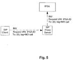
Fig. 5 shows a diagram illustrating an IPSA invocation on the basis of an originating call according to another embodiment of the present invention. -
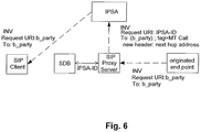
Fig. 6 shows a diagram illustrating an IPSA invocation on the basis of a terminating call according to an embodiment of the present invention. -
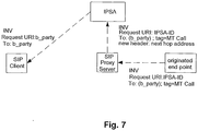
Fig. 7 shows a diagram illustrating an IPSA invocation on the basis of a terminating call according to another embodiment of the present invention. -
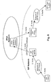
Fig. 8 shows a diagram illustrating routing of SIP calls from a SIP network to an IPSA network and from the IPSA network to the SIP network in greater detail. - The idea of the present invention is to separate a service provider network from a bearer provider network in an IPT (Internet Protocol Telephony) environment. According to preferred embodiments of the present invention, which are to be described in the following, this concept is realized by using SIP (Session Initiation Protocol) as a control protocol between an IP network called IPSA (IP based Services Architecture) network, an IPT provider network called SIP network and an end-user terminal (user equipment).
- In
Fig. 1 , functional elements involved in service triggering and control in the communication system according to an embodiment are shown. A SIP client represents an end-user's terminal attaching to the communication system using SIP methods. The end-user's terminal may be called user equipment (UE) and, for example, may be a PC (Personal Computer) or laptop running an IPT SIP client application. - A SIP proxy server is part of the SIP network that provides bearer connection and call related functions like call routing capabilities to the end-user. In the SIP network, an SDB (Subscriber Database) may be present, which contains subscriber subscription information such as authentication data and IPSA-ID (IPSA-Identifier).
- The IPSA network shown in
Fig. 1 is an IP based service architecture platform that offers services like telephony and other IP type of services to the end-user. A user has a unique identity called IPSA-ID within one IPSA cloud. The ID may be formed out of the user name and IPSA provider's domain name as ipsa-user@ipsa-provider.com. - An IP cloud shown in
Fig. 1 represents an IP backbone network to interconnect the SIP client, SIP network and IPSA network. -
Figs. 2 and3 illustrate a registration of a SIP client to the communication system, and in particular to the IPSA network shown inFig. 1 . - Some services such as "Presence" need to know whether the client's terminal is ready to receive a call or not, i.e. whether the client is attached to the network or not. When this type of service is implemented in IPSA, the IPSA network needs to know the status of the client.
-
Fig. 2 shows a first way of registering an end-user to the IPSA network. In this way of registering, the SDB contains an IPSA-ID in the form of a logical name at some domain, for example "john.doe@some.ipsa.com". Whenever the SIP client sends a SIP REGISTER message to the SIP proxy server, the SIP proxy server registers the SIP client to the SIP network and also fetches an IPSA-ID for the end-user represented by the SIP client from the SDB. If an IPSA-ID in the SDB is associated with the end-user, the SIP proxy server generates another REGISTER message with the IPSA-ID and sends it towards the IPSA network. On the basis of this register message, the IPSA network is able to register the SIP client. -
Fig. 3 shows another possibility of registering an end-user to the IPSA network. In this way of registering, the SIP client directly registers to the IPSA network using its IPSA-ID in another REGISTER message. -
Option 1 shown inFig. 2 allows the IPT provider to retain the control of which IPSA provider is providing the end-user's services, whileoption 2 shown inFig. 3 gives total control to the user with respect to the choice of the IPSA provider. - Next, an IPSA invocation on the basis of an originating call will be described.
Fig. 4 shows a first method of invoking IPSA on the basis of an originating call. A SIP client sends an INVITE message towards the SIP network, which message is received by a SIP proxy server. The SIP proxy server can route this end-user initiated call towards the IPSA network when an IPSA-ID found in the SDB is associated with the called party B, i.e. with the request URI (Uniform Resource Identifier) B in the INVITE message. When the IPSA-ID is found in the SDB, the SIP proxy server changes the request URI to IPSA-ID and indicates that this is an originating call in a new SIP header and routes the INVITE message to the IPSA network. - Optionally, as shown in
Fig. 5 , the SIP client can also send the INVITE message directly to the IPSA network via the SIP proxy server by indicating the request URI with an IPSA-ID of the called party. The SIP proxy server then analyses the request URI and forwards the INVITE message to the IPSA network. - Next, an IPSA invocation on the basis of a terminating call will be described.
Fig. 6 shows a first method of invoking IPSA on the basis of a terminating call. When a SIP proxy server receives an INVITE message from an originated endpoint inviting a SIP client called b_party to a call, it fetches an IPSA-ID for the called b_party from the SDB. If an IPSA-ID is associated with the called b_party, the SIP proxy server routes the INVITE message to the IPSA network, using the fetched IPSA-ID along with a new SIP header indicating that this is a terminating call. The SIP proxy server further includes a Gateway SIP proxy address or hop address in the routed INVITE message, which will be described in greater detail in connection withFig. 8 . The IPSA network should use this address for further routing. The IPSA network then executes any terminating services, and if further routing is needed, it uses the address provided by the SIP proxy server to reach the end-user, i.e. the b_party. - Optionally, as shown in
Fig. 7 , the INVITE message received by the SIP proxy server already contains the IPSA-ID in the request URI as well as the terminated call indication. After having analyzed the request URI, the SIP proxy server adds the hop address for further routing to the INVITE message and forwards it to the IPSA network. - Now referring to
Fig. 8 , a mechanism for appropriately routing service invocations between the IPSA network and the SIP network is described. - When the SIP network re-routes SIP calls to the IPSA network in order to have services executed for the subscriber or SIP client involved in the call, the IPSA network may have, as part of service execution, to re-route the SIP call or initiate a new SIP signaling, e.g. call setup, INFO methods, etc., through the SIP network. For example, considering a loop detection for INVITE messages, the SIP signaling cannot be sent back to the element in the SIP network that routed the call to the IPSA network and the IPSA network does not necessarily know the topology of the SIP network.
- When a SIP proxy server in the SIP network routes a SIP call to the IPSA network, the SIP network provides an address of a SIP proxy in the SIP network to be used as a gateway for SIP signaling which the IPSA network needs to exchange with the SIP network.
- For example, according to
Fig. 8 , a SIP client sends an INVITE message to the SIP network for inviting another SIP client (b_party). The INVITE message is received by a SIP proxy server via a network of SIP proxies forwarding the message. The SIP proxy server routes the INVITE message towards the IPSA network and indicates a gateway SIP proxy address in the message. Now, an IPSA network element receiving the message knows to which SIP proxy server in the SIP network the call has to be routed in order to reach the b_party. Hence, the IPSA network element routes the INVITE message to the gateway SIP proxy, the address of which has been indicated by the SIP proxy server. The b_party receives the INVITE message from the gateway SIP proxy via the network of SIP proxies. - The provision of the gateway address to the IPSA network can be implemented by adding a parameter in an SDP (Session Description Protocol) descriptor contained in the SIP message routed from the SIP proxy server to the IPSA network and containing the address of the gateway SIP proxy. Alternatively, the address can be indicated to the IPSA network by adding a SIP header to the SIP message routed from the SIP proxy server to the IPSA network and containing the address of the gateway SIP proxy.
- While the invention has been described with reference to preferred embodiments, the description is illustrative of the invention and is not to be construed as limiting the invention. Various modifications and applications may occur to those skilled in the art without departing from the scope of the invention as defined by the appended claims.
Claims (25)
- A session initiation protocol, SIP, proxy server which is part of a SIP network and which is interconnected to an Internet Protocol-based Services Architecture, IPSA network, wherein said SIP proxy server is arranged to:receive a SIP message;analyze the SIP message; anddepending on the analyzing result, perform further functions,wherein, when said SIP proxy server receives, from a SIP client, a control protocol message for registering the SIP client, the SIP proxy server is arranged to analyze a user address in the control protocol message, and to register the SIP client to the SIP network in accordance with the user address,characterised in that the SIP proxy server is further arranged to:fetch an IPSA user identification address related to a specific domain of the IPSA network and to the user address from a subscriber database in the SIP network;generate a control protocol message with the fetched IPSA user identification address; andsend the generated control protocol message towards the IPSA network for registering the SIP client to the IPSA network.
- A SIP proxy server according to claim 1, wherein, when said SIP proxy server receives, from the SIP client, an initiating control protocol message for initiating a call, the SIP proxy server is arranged to:analyze the initiating control protocol message; andif an IPSA user identification address of a called party and an originating call indication are present in the initiating control protocol message, forward the initiating control protocol message to the IPSA network.
- A SIP proxy server according to claim 1, wherein, when said SIP proxy server receives, from a SIP client, an initiating control protocol message for initiating a call, the SIP proxy server is arranged to:analyze the initiating control protocol message; andif a called party address is present in the initiating control protocol message:fetch an IPSA user identification address related to the called party address from a subscriber database in the SIP network; andsend a control protocol message with the IPSA user identification address related to the called party address and an originating call indication towards the IPSA network.
- A SIP proxy server according to claim 1, wherein, when said SIP proxy server receives an initiating control protocol message indicating an initiated call to a SIP client, the SIP proxy server is arranged to:analyze the initiating control protocol message; andif a user identification address and a terminating call indication are present in the initiating control protocol message, forward the initiating control protocol message to the IPSA network.
- A SIP proxy server according to claim 1, wherein, when said SIP proxy server receives an initiating control protocol message indicating an initiated call to a SIP client, the SIP proxy server is arranged to:analyze the initiating control protocol message; andif a user address is present in the initiating control protocol message:fetch IPSA user identification address related to the user address from the subscriber database; andsend a control protocol message with the IPSA user identification address related to the user address and a terminating call indication towards the IPSA network.
- A SIP proxy server according any of claims 4 and 5, wherein said SIP proxy server is arranged to indicate an address of another serving entity in the SIP network in the control protocol message indicating the initiated call and sent towards the IPSA network.
- A SIP proxy server according to claim 6, wherein said SIP proxy server is arranged to indicate the address of the other serving entity by adding a parameter containing said address to a descriptor contained in the control protocol message indicating the initiated call which is sent towards the IPSA network.
- A SIP proxy server according to claim 6, wherein said SIP proxy server is arranged to indicate the address of the other serving entity by adding a control protocol header containing said address to the control protocol message indicating the initiated call which is sent towards the IPSA network.
- A SIP proxy server according to claim 3, wherein said SIP proxy server is arranged to add a new control protocol header comprising the originating call indication to the control protocol message sent towards the IPSA network.
- A SIP proxy server according to claim 5, wherein said SIP proxy server is arranged to add a new control protocol header comprising the terminating call indication to the control protocol message sent towards the IPSA network.
- A SIP proxy server according to any preceding claim, wherein the control protocol comprises Session Initiation Protocol.
- A method used in a Session Initiation Protocol, SIP, proxy server which is part of a SIP network and which is interconnected to an Internet Protocol-based Services Architecture, IPSA, network, comprising:receiving a SIP message;analyzing the SIP message; anddepending on the analyzing result, performing further functions,the method further comprising:when receiving, from a SIP client, a control protocol message for registering the SIP client:analyzing a user address in the control protocol message;registering the SIP client to the SIP network in accordance with the user address, and characterised by further comprising:fetching an IPSA user identification address related to a domain of the IPSA network and to the user address from a subscriber database in the SIP network;generating a control protocol message with the IPSA user identification address; andsending the generated control protocol message towards the IPSA network for registering the SIP client to the IPSA network.
- A method according to claim 12, further comprising: when an initiating control protocol message for initiating a call is received from a SIP client, analyzing the initiating control protocol message and, if an IPSA user identification address of a called party and an originating call indication are present in the initiating control protocol message, forwarding the initiating control protocol message to the IPSA network.
- A method according to claim 12, further comprising: when an initiating control protocol message for initiating a call is received from a SIP client:analyzing the initiating control protocol message; andif a called party address is present in the initiating control protocol message:fetching an IPSA user identification address related to the called party address from a subscriber database in the SIP network; andsending a control protocol message with the IPSA user identification address and an originating call indication towards the IPSA network.
- A method according to claim 12, further comprising: when an initiating control protocol message indicating an initiated call to a SIP client is received:analyzing the initiating control protocol message; andif a user identification address and a terminating call indication are present in the control protocol message, forwarding the initiating control protocol message to the IPSA network.
- A method according to claim 12, further comprising: when an initiating control protocol message indicating an initiated call to a SIP client is received:analyzing the initiating control protocol message; andif a user identification address is present in the initiating control protocol message:fetching an IPSA user identification address related to the user address from the subscriber database; andsending a control protocol message with the IPSA user identification address and a terminating call indication towards the IPSA network.
- A method according to any of claims 15 and 16, further comprising: indicating an address of another serving entity in the SIP network in the control protocol message indicating the initiated call and sent towards the IPSA network.
- A method according to claim 17, further comprising: indicating the address of the other serving entity by adding a parameter containing the address to a descriptor contained in the control protocol message indicating the initiated call which is sent towards the IPSA network.
- A method according to claim 17, further comprising: indicating the address of the other serving entity by adding a control protocol header containing the address to the control protocol message indicating the initiated call which is sent towards the IPSA network.
- A method according to claim 14, further comprising: adding a new control protocol header comprising the originating call indication to the control protocol message sent towards the IPSA network.
- A method according to claim 16, further comprising: adding a new control protocol header comprising the terminating call indication to the control protocol message sent towards the IPSA network.
- A method according to any of claims 12 to 21, wherein the control protocol comprises Session Initiation Protocol.
- A computer program product including a program for a processing device, comprising software code portions for performing the steps of any one of claims 12 to 22 when the program is run on the processing device.
- The computer program product according to claim 23, wherein the computer program product comprises a computer-readable medium on which the software code portions are stored.
- The computer program product according to claim 23, wherein the program is directly loadable into an internal memory of the processing device.
Applications Claiming Priority (3)
| Application Number | Priority Date | Filing Date | Title |
|---|---|---|---|
| US792611 | 1997-01-31 | ||
| US09/792,611 US7266593B2 (en) | 2001-02-23 | 2001-02-23 | IP based service architecture |
| PCT/EP2002/001908 WO2002069616A1 (en) | 2001-02-23 | 2002-02-22 | Separation of basic call functions and service provision in ip networks |
Publications (2)
| Publication Number | Publication Date |
|---|---|
| EP1364523A1 EP1364523A1 (en) | 2003-11-26 |
| EP1364523B1 true EP1364523B1 (en) | 2018-03-28 |
Family
ID=25157490
Family Applications (1)
| Application Number | Title | Priority Date | Filing Date |
|---|---|---|---|
| EP02727325.9A Expired - Lifetime EP1364523B1 (en) | 2001-02-23 | 2002-02-22 | SIP Proxy Server which supports double registration in a bearer provider network and a service provider network |
Country Status (7)
| Country | Link |
|---|---|
| US (1) | US7266593B2 (en) |
| EP (1) | EP1364523B1 (en) |
| JP (1) | JP3928953B2 (en) |
| KR (1) | KR100554090B1 (en) |
| CN (1) | CN100576862C (en) |
| CA (1) | CA2439086C (en) |
| WO (1) | WO2002069616A1 (en) |
Families Citing this family (20)
| Publication number | Priority date | Publication date | Assignee | Title |
|---|---|---|---|---|
| US7369535B2 (en) * | 2001-06-11 | 2008-05-06 | Level 3 Communications, Llc | Voice over Internet Protocol real time protocol routing |
| US7362745B1 (en) | 2001-09-05 | 2008-04-22 | Sprint Communications Company L.P. | End-user systems for communication services over peer-to-peer internet protocol connections between service providers |
| US8271619B1 (en) | 2001-09-05 | 2012-09-18 | Sprint Communications Company, L.P. | Establishing end-user communication services that use peer-to-peer internet protocol connections between service providers |
| US6751216B2 (en) * | 2001-09-05 | 2004-06-15 | Sprint Communications Company L.P. | Providing end-user communication services over peer-to-peer internet protocol connections between service providers |
| US6888828B1 (en) * | 2001-10-02 | 2005-05-03 | Nokia Corporation | System and method for providing at least one service obtained from a service network for a user in a packet switched communication network |
| GB0124436D0 (en) * | 2001-10-11 | 2001-12-05 | Nokia Corp | Terminal-based instruction execution in an ip communications network |
| US7415026B2 (en) * | 2002-02-04 | 2008-08-19 | Qualcomm Incorporated | Method and apparatus for session release in a communication system |
| US20030177242A1 (en) * | 2002-03-15 | 2003-09-18 | Nokia, Inc. | Trigger-based session completion using external parties |
| US8234360B2 (en) * | 2002-04-23 | 2012-07-31 | Microsoft Corporation | System for processing messages to support network telephony services |
| CN100388733C (en) * | 2002-12-25 | 2008-05-14 | 中兴通讯股份有限公司 | A method of call routing in a session initiation protocol network |
| US7490155B1 (en) * | 2003-03-13 | 2009-02-10 | 3Com Corporation | Management and control for interactive media sessions |
| US7508754B1 (en) * | 2004-02-27 | 2009-03-24 | Sprint Spectrum L.P. | Method and system to support internal calling upon loss of connection with IP Centrex server |
| JP4028853B2 (en) | 2004-03-30 | 2007-12-26 | 株式会社日立製作所 | Information service communication network system and session management server |
| ATE523018T1 (en) * | 2004-09-29 | 2011-09-15 | Sonus Networks Inc | CONTROLLING TIME-CRITICAL DATA IN A PACKET-BASED NETWORK |
| US20060265501A1 (en) * | 2005-05-20 | 2006-11-23 | Anchorfree Wireless | System and method for enabling wireless internet access in public areas |
| WO2010047229A1 (en) * | 2008-10-21 | 2010-04-29 | 三菱電機株式会社 | Communication system and communication device |
| WO2012041354A1 (en) * | 2010-10-01 | 2012-04-05 | Telefonaktiebolaget Lm Ericsson (Publ) | Service based release of a subscriber registrar server from a signalling path in an internet protocol communication network. |
| CN103067428B (en) * | 2011-10-21 | 2016-08-10 | 华为技术有限公司 | Base station, service processing method and cloud computing system |
| CN108512863B (en) * | 2018-06-06 | 2021-03-16 | 中国人民解放军陆军工程大学 | Voice communication control system of multi-type SIP equipment |
| US11303754B1 (en) * | 2021-01-13 | 2022-04-12 | Verizon Patent And Licensing Inc. | Ringless voicemail attempt detection |
Family Cites Families (11)
| Publication number | Priority date | Publication date | Assignee | Title |
|---|---|---|---|---|
| US6009469A (en) * | 1995-09-25 | 1999-12-28 | Netspeak Corporation | Graphic user interface for internet telephony application |
| US6009468A (en) | 1997-06-30 | 1999-12-28 | Ericsson, Inc. | Employing feedback data and congestion ranking to minimize contention delay in a multi-slot Mac protocol |
| DE19832290B4 (en) * | 1998-07-17 | 2011-12-08 | Telefonaktiebolaget Lm Ericsson (Publ) | Communication system and method for establishing connections between terminals of a first and a second communication network |
| US6161134A (en) * | 1998-10-30 | 2000-12-12 | 3Com Corporation | Method, apparatus and communications system for companion information and network appliances |
| US6600736B1 (en) * | 1999-03-31 | 2003-07-29 | Lucent Technologies Inc. | Method of providing transfer capability on web-based interactive voice response services |
| US6687356B1 (en) | 1999-06-18 | 2004-02-03 | Telefonaktiebolaget Lm Ericsson | System and method for providing device-aware services in an integrated telecommunications network |
| US6625141B1 (en) * | 1999-06-18 | 2003-09-23 | Telefonaktiebolaget L M Ericsson (Publ) | System and method for providing value-added services (VAS) in an integrated telecommunications network using session initiation protocol (SIP) |
| US6678265B1 (en) * | 1999-12-30 | 2004-01-13 | At&T Corp. | Local number portability database for on-net IP call |
| US6373817B1 (en) * | 1999-12-30 | 2002-04-16 | At&T Corp. | Chase me system |
| US6741586B1 (en) * | 2000-05-31 | 2004-05-25 | 3Com Corporation | System and method for sharing computer screens over a telephony network |
| US7484240B2 (en) * | 2001-07-13 | 2009-01-27 | Nokia Corporation | Mechanism to allow authentication of terminated SIP calls |
-
2001
- 2001-02-23 US US09/792,611 patent/US7266593B2/en not_active Expired - Lifetime
-
2002
- 2002-02-22 CA CA002439086A patent/CA2439086C/en not_active Expired - Fee Related
- 2002-02-22 EP EP02727325.9A patent/EP1364523B1/en not_active Expired - Lifetime
- 2002-02-22 KR KR1020037010436A patent/KR100554090B1/en not_active Expired - Fee Related
- 2002-02-22 JP JP2002568617A patent/JP3928953B2/en not_active Expired - Lifetime
- 2002-02-22 CN CN02805288A patent/CN100576862C/en not_active Expired - Lifetime
- 2002-02-22 WO PCT/EP2002/001908 patent/WO2002069616A1/en not_active Ceased
Also Published As
| Publication number | Publication date |
|---|---|
| CA2439086C (en) | 2008-10-07 |
| CN1500340A (en) | 2004-05-26 |
| US7266593B2 (en) | 2007-09-04 |
| EP1364523A1 (en) | 2003-11-26 |
| KR100554090B1 (en) | 2006-02-22 |
| JP2004523174A (en) | 2004-07-29 |
| JP3928953B2 (en) | 2007-06-13 |
| US20020120759A1 (en) | 2002-08-29 |
| CN100576862C (en) | 2009-12-30 |
| KR20030081433A (en) | 2003-10-17 |
| WO2002069616A1 (en) | 2002-09-06 |
| CA2439086A1 (en) | 2002-09-06 |
Similar Documents
| Publication | Publication Date | Title |
|---|---|---|
| US7266593B2 (en) | IP based service architecture | |
| US7916685B2 (en) | Methods, systems, and computer program products for supporting database access in an internet protocol multimedia subsystem (IMS) network environment | |
| EP2093970B1 (en) | Call service handling in an IMS-based system | |
| US8634412B2 (en) | Session initiation protocol (SIP) message incorporating a multi-purpose internet mail extension (MIME) media type for describing the content and format of information included in the SIP message | |
| US6940847B1 (en) | System and method for providing access to service nodes from entities disposed in an integrated telecommunications network | |
| US20070097879A1 (en) | Method and communication system for automatically discovering the multimedia service capability | |
| CN101258732B (en) | Methods, systems, and computer program products for triggering SIP nodes to include SS7 routing information in respone messages including information requested by SS7 nodes | |
| EP1606921B1 (en) | Request redirection handling in imc | |
| US9756090B2 (en) | Technique for providing services in a service provisioning network | |
| KR20070047293A (en) | Method and apparatus for providing a correlation means in a hybrid telecommunications network | |
| EP1790149A1 (en) | Method and session initiation protocol (sip) server for the exchange of end-point capabilities | |
| EP2380338B1 (en) | Setting up a call from a non- ims to an ims network whereby the gateway interfaces the hss | |
| CN101313553B (en) | Message handling in an IP multimedia subsystem | |
| CN1875603B (en) | Method and apparatus for load-balancing | |
| KR100807863B1 (en) | Service provisioning in a communication system | |
| WO2009121281A1 (en) | A method for invoking a service in ims network, system and device thereof | |
| CN101282288B (en) | System, apparatus and method for processing services in packet field network | |
| US8094801B2 (en) | Providing of service(s) by a service control component to telephony device(s) on a call through employment data stream(s) associated with the call |
Legal Events
| Date | Code | Title | Description |
|---|---|---|---|
| PUAI | Public reference made under article 153(3) epc to a published international application that has entered the european phase |
Free format text: ORIGINAL CODE: 0009012 |
|
| 17P | Request for examination filed |
Effective date: 20030922 |
|
| AK | Designated contracting states |
Kind code of ref document: A1 Designated state(s): AT BE CH CY DE DK ES FI FR GB GR IE IT LI LU MC NL PT SE TR |
|
| AX | Request for extension of the european patent |
Extension state: AL LT LV MK RO SI |
|
| 17Q | First examination report despatched |
Effective date: 20060808 |
|
| RAP1 | Party data changed (applicant data changed or rights of an application transferred) |
Owner name: NOKIA CORPORATION |
|
| RAP1 | Party data changed (applicant data changed or rights of an application transferred) |
Owner name: NOKIA TECHNOLOGIES OY |
|
| GRAP | Despatch of communication of intention to grant a patent |
Free format text: ORIGINAL CODE: EPIDOSNIGR1 |
|
| STAA | Information on the status of an ep patent application or granted ep patent |
Free format text: STATUS: GRANT OF PATENT IS INTENDED |
|
| INTG | Intention to grant announced |
Effective date: 20170925 |
|
| GRAS | Grant fee paid |
Free format text: ORIGINAL CODE: EPIDOSNIGR3 |
|
| GRAA | (expected) grant |
Free format text: ORIGINAL CODE: 0009210 |
|
| STAA | Information on the status of an ep patent application or granted ep patent |
Free format text: STATUS: THE PATENT HAS BEEN GRANTED |
|
| AK | Designated contracting states |
Kind code of ref document: B1 Designated state(s): AT BE CH CY DE DK ES FI FR GB GR IE IT LI LU MC NL PT SE TR |
|
| REG | Reference to a national code |
Ref country code: GB Ref legal event code: FG4D |
|
| REG | Reference to a national code |
Ref country code: CH Ref legal event code: EP |
|
| REG | Reference to a national code |
Ref country code: AT Ref legal event code: REF Ref document number: 984414 Country of ref document: AT Kind code of ref document: T Effective date: 20180415 |
|
| REG | Reference to a national code |
Ref country code: IE Ref legal event code: FG4D |
|
| REG | Reference to a national code |
Ref country code: DE Ref legal event code: R096 Ref document number: 60249352 Country of ref document: DE |
|
| PG25 | Lapsed in a contracting state [announced via postgrant information from national office to epo] |
Ref country code: FI Free format text: LAPSE BECAUSE OF FAILURE TO SUBMIT A TRANSLATION OF THE DESCRIPTION OR TO PAY THE FEE WITHIN THE PRESCRIBED TIME-LIMIT Effective date: 20180328 |
|
| REG | Reference to a national code |
Ref country code: NL Ref legal event code: MP Effective date: 20180328 |
|
| PG25 | Lapsed in a contracting state [announced via postgrant information from national office to epo] |
Ref country code: GR Free format text: LAPSE BECAUSE OF FAILURE TO SUBMIT A TRANSLATION OF THE DESCRIPTION OR TO PAY THE FEE WITHIN THE PRESCRIBED TIME-LIMIT Effective date: 20180629 Ref country code: SE Free format text: LAPSE BECAUSE OF FAILURE TO SUBMIT A TRANSLATION OF THE DESCRIPTION OR TO PAY THE FEE WITHIN THE PRESCRIBED TIME-LIMIT Effective date: 20180328 |
|
| PG25 | Lapsed in a contracting state [announced via postgrant information from national office to epo] |
Ref country code: NL Free format text: LAPSE BECAUSE OF FAILURE TO SUBMIT A TRANSLATION OF THE DESCRIPTION OR TO PAY THE FEE WITHIN THE PRESCRIBED TIME-LIMIT Effective date: 20180328 Ref country code: ES Free format text: LAPSE BECAUSE OF FAILURE TO SUBMIT A TRANSLATION OF THE DESCRIPTION OR TO PAY THE FEE WITHIN THE PRESCRIBED TIME-LIMIT Effective date: 20180328 |
|
| REG | Reference to a national code |
Ref country code: AT Ref legal event code: MK05 Ref document number: 984414 Country of ref document: AT Kind code of ref document: T Effective date: 20180328 |
|
| PG25 | Lapsed in a contracting state [announced via postgrant information from national office to epo] |
Ref country code: PT Free format text: LAPSE BECAUSE OF FAILURE TO SUBMIT A TRANSLATION OF THE DESCRIPTION OR TO PAY THE FEE WITHIN THE PRESCRIBED TIME-LIMIT Effective date: 20180730 |
|
| REG | Reference to a national code |
Ref country code: DE Ref legal event code: R097 Ref document number: 60249352 Country of ref document: DE |
|
| PG25 | Lapsed in a contracting state [announced via postgrant information from national office to epo] |
Ref country code: DK Free format text: LAPSE BECAUSE OF FAILURE TO SUBMIT A TRANSLATION OF THE DESCRIPTION OR TO PAY THE FEE WITHIN THE PRESCRIBED TIME-LIMIT Effective date: 20180328 Ref country code: AT Free format text: LAPSE BECAUSE OF FAILURE TO SUBMIT A TRANSLATION OF THE DESCRIPTION OR TO PAY THE FEE WITHIN THE PRESCRIBED TIME-LIMIT Effective date: 20180328 |
|
| PLBE | No opposition filed within time limit |
Free format text: ORIGINAL CODE: 0009261 |
|
| STAA | Information on the status of an ep patent application or granted ep patent |
Free format text: STATUS: NO OPPOSITION FILED WITHIN TIME LIMIT |
|
| PG25 | Lapsed in a contracting state [announced via postgrant information from national office to epo] |
Ref country code: IT Free format text: LAPSE BECAUSE OF FAILURE TO SUBMIT A TRANSLATION OF THE DESCRIPTION OR TO PAY THE FEE WITHIN THE PRESCRIBED TIME-LIMIT Effective date: 20180328 |
|
| 26N | No opposition filed |
Effective date: 20190103 |
|
| REG | Reference to a national code |
Ref country code: CH Ref legal event code: PL |
|
| GBPC | Gb: european patent ceased through non-payment of renewal fee |
Effective date: 20190222 |
|
| PG25 | Lapsed in a contracting state [announced via postgrant information from national office to epo] |
Ref country code: MC Free format text: LAPSE BECAUSE OF FAILURE TO SUBMIT A TRANSLATION OF THE DESCRIPTION OR TO PAY THE FEE WITHIN THE PRESCRIBED TIME-LIMIT Effective date: 20180328 Ref country code: LU Free format text: LAPSE BECAUSE OF NON-PAYMENT OF DUE FEES Effective date: 20190222 |
|
| REG | Reference to a national code |
Ref country code: BE Ref legal event code: MM Effective date: 20190228 |
|
| REG | Reference to a national code |
Ref country code: IE Ref legal event code: MM4A |
|
| PG25 | Lapsed in a contracting state [announced via postgrant information from national office to epo] |
Ref country code: CH Free format text: LAPSE BECAUSE OF NON-PAYMENT OF DUE FEES Effective date: 20190228 Ref country code: LI Free format text: LAPSE BECAUSE OF NON-PAYMENT OF DUE FEES Effective date: 20190228 |
|
| PG25 | Lapsed in a contracting state [announced via postgrant information from national office to epo] |
Ref country code: GB Free format text: LAPSE BECAUSE OF NON-PAYMENT OF DUE FEES Effective date: 20190222 Ref country code: IE Free format text: LAPSE BECAUSE OF NON-PAYMENT OF DUE FEES Effective date: 20190222 |
|
| PG25 | Lapsed in a contracting state [announced via postgrant information from national office to epo] |
Ref country code: FR Free format text: LAPSE BECAUSE OF NON-PAYMENT OF DUE FEES Effective date: 20190228 Ref country code: BE Free format text: LAPSE BECAUSE OF NON-PAYMENT OF DUE FEES Effective date: 20190228 |
|
| PG25 | Lapsed in a contracting state [announced via postgrant information from national office to epo] |
Ref country code: TR Free format text: LAPSE BECAUSE OF FAILURE TO SUBMIT A TRANSLATION OF THE DESCRIPTION OR TO PAY THE FEE WITHIN THE PRESCRIBED TIME-LIMIT Effective date: 20180328 |
|
| PG25 | Lapsed in a contracting state [announced via postgrant information from national office to epo] |
Ref country code: CY Free format text: LAPSE BECAUSE OF FAILURE TO SUBMIT A TRANSLATION OF THE DESCRIPTION OR TO PAY THE FEE WITHIN THE PRESCRIBED TIME-LIMIT Effective date: 20180328 |
|
| PGFP | Annual fee paid to national office [announced via postgrant information from national office to epo] |
Ref country code: DE Payment date: 20210209 Year of fee payment: 20 |
|
| REG | Reference to a national code |
Ref country code: DE Ref legal event code: R071 Ref document number: 60249352 Country of ref document: DE |