EP1364087B1 - Installation for producing non-woven textile webs with jet fluids leaving no visible mark - Google Patents
Installation for producing non-woven textile webs with jet fluids leaving no visible mark Download PDFInfo
- Publication number
- EP1364087B1 EP1364087B1 EP01980607A EP01980607A EP1364087B1 EP 1364087 B1 EP1364087 B1 EP 1364087B1 EP 01980607 A EP01980607 A EP 01980607A EP 01980607 A EP01980607 A EP 01980607A EP 1364087 B1 EP1364087 B1 EP 1364087B1
- Authority
- EP
- European Patent Office
- Prior art keywords
- installation according
- jets
- web
- conveyor
- installation
- Prior art date
- Legal status (The legal status is an assumption and is not a legal conclusion. Google has not performed a legal analysis and makes no representation as to the accuracy of the status listed.)
- Expired - Lifetime
Links
- 238000009434 installation Methods 0.000 title claims abstract description 18
- 239000004753 textile Substances 0.000 title abstract description 4
- 239000012530 fluid Substances 0.000 title description 6
- 230000010355 oscillation Effects 0.000 claims description 22
- XLYOFNOQVPJJNP-UHFFFAOYSA-N water Substances O XLYOFNOQVPJJNP-UHFFFAOYSA-N 0.000 claims description 17
- 230000003534 oscillatory effect Effects 0.000 claims 5
- 239000000835 fiber Substances 0.000 description 7
- HEMHJVSKTPXQMS-UHFFFAOYSA-M Sodium hydroxide Chemical compound [OH-].[Na+] HEMHJVSKTPXQMS-UHFFFAOYSA-M 0.000 description 6
- 230000008034 disappearance Effects 0.000 description 3
- 238000006073 displacement reaction Methods 0.000 description 3
- 230000000694 effects Effects 0.000 description 3
- 238000011282 treatment Methods 0.000 description 3
- 238000007596 consolidation process Methods 0.000 description 2
- 238000000034 method Methods 0.000 description 2
- 235000011121 sodium hydroxide Nutrition 0.000 description 2
- 238000009987 spinning Methods 0.000 description 2
- 206010063493 Premature ageing Diseases 0.000 description 1
- 208000032038 Premature aging Diseases 0.000 description 1
- 230000002378 acidificating effect Effects 0.000 description 1
- 230000015572 biosynthetic process Effects 0.000 description 1
- 238000005336 cracking Methods 0.000 description 1
- 230000008021 deposition Effects 0.000 description 1
- 238000005470 impregnation Methods 0.000 description 1
- 239000007788 liquid Substances 0.000 description 1
- 239000002184 metal Substances 0.000 description 1
- 239000004745 nonwoven fabric Substances 0.000 description 1
- 238000009991 scouring Methods 0.000 description 1
- 239000000126 substance Substances 0.000 description 1
Images

Classifications
-
- D—TEXTILES; PAPER
- D04—BRAIDING; LACE-MAKING; KNITTING; TRIMMINGS; NON-WOVEN FABRICS
- D04H—MAKING TEXTILE FABRICS, e.g. FROM FIBRES OR FILAMENTARY MATERIAL; FABRICS MADE BY SUCH PROCESSES OR APPARATUS, e.g. FELTS, NON-WOVEN FABRICS; COTTON-WOOL; WADDING ; NON-WOVEN FABRICS FROM STAPLE FIBRES, FILAMENTS OR YARNS, BONDED WITH AT LEAST ONE WEB-LIKE MATERIAL DURING THEIR CONSOLIDATION
- D04H18/00—Needling machines
- D04H18/04—Needling machines with water jets
Definitions
- the invention relates to an improvement made to the installations for producing fibrous nonwoven webs whose cohesion is obtained by intermingling the fibers in the thickness of said web through the action of fluid jets, and more particularly jets of water, of small diameter and having a high speed.
- the US-A-3,906,130 relates to a perforated nonwoven.
- the oscillations are intended to promote the transverse deposition of the filaments and the formation of filament loops.
- FIG. 5 of this document also shows that the bodies delivering the jets of water (item 36) intended for the consolidation of the filament layer are placed on a non-oscillating conveyor 15 independent of the oscillating conveyor 1 on which the filaments are deposited.
- the inventor specifies that the equipment 33, 34 and 35 disposed above the conveyor 1 are impregnating nozzles of a caustic soda solution for "scouring" treatment.
- This treatment with caustic soda can in no way be assimilated to consolidation by water jets, in other words to a hydraulic entanglement of the fibers. It is usually carried out at pressures not exceeding 5 bar and by flat or conical jets.
- the US-A-4,252,590 relates to a method of forming a web of continuous filaments whose transverse properties are improved by a transverse displacement of the support 3.
- the US-A-3 833 438 discloses a particular "wet" spinning system in which the extruded and coagulated filaments are received on a conveyor driven by a transverse oscillation movement.
- markers 29 and 30 correspond to impregnation systems for acidic or basic chemical treatments as is practiced on filament webs after spinning them.
- the water jets used to interleave the fibers leave visible marks on the surface of the nonwovens.
- Vibrations transmitted to hydraulic equipment cause premature aging of equipment and hazards for personnel.
- the present invention relates to a facility for producing nonwoven fibrous webs for entangling the fibers of a nonwoven web by means of jets of water without having visible marks and impressions of the water jets in and on the surface of nonwoven webs and without the need to move hydraulic equipment.
- the invention relates to a plant for producing nonwoven fibrous webs comprising a conveyor on a strand from which a nonwoven fibrous web passes under an injector which projects onto the sheet water jets suitable for hydroentangling and preferably above a box communicating with a source of depression.
- the oscillation techniques of the injector like that of the conveyor, have the disadvantage of moving very large masses in motion.
- the injector weighs between 1000 and 1500 kg. Devices for moving such large masses are extremely expensive.
- the installation is such that the fibrous web passes between the injector and a box communicating with a source of depression and the means is arranged to give the movement of oscillation at the caisson.
- the oscillation movement may be purely perpendicular to the direction of movement of the strand but it may also be inclined with respect to this direction, the essential point being that there is a component of the oscillation motion which is perpendicular to the direction of motion. displacement of the strand and the direction of the jets which is most often vertical.
- the frequency in Hz represents from 2 to 20 times the speed of the sheet expressed in m / min, this speed of the sheet being preferably between 5 and 50 m / min.
- the number of jets be between 12 and 77 jets / cm of the portion of the web receiving the jet.
- the fluid sprayed by the injector is a liquid and in particular water.
- the jets project fluids at a pressure which is preferably between 20 and 600 bar.
- the jets are cylindrical and come from nozzles with a diameter of 80 to 170 microns to give jets of the same shape and diameter.
- the box is suspended mounted on resilient means including springs or silent blocks.
- the conveyor is usually a metal or plastic endless conveyor and the fluid can pass through the conveyor.
- injectors are associated with one and the same box.
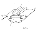
- the figure 3 illustrates a variant.
- a fibrous nonwoven web (not shown) passes. ) whose fibers should be better entangled.
- there are two benches 4 of injectors providing jets of water at 300 bars with a diameter of 120 ⁇ . These jets are directed vertically on the web 3 and in the part above the injectors 4 there are fifty jets per centimeter of the web.
- Below the strand 3, and facing the injector 4 is mounted spring 5 a box 6 communicating with a source 7 of vacuum.
- the caisson is animated, by means represented at figure 2 , an oscillation movement symbolized by the horizontal double arrow F and perpendicular to the direction of movement of the strand 3.
- the amplitude of the oscillations is 4 mm.
- the box performs fifty oscillations per second.
- the oscillation movement is obtained by a connecting rod device 8 and crank 9 rotated by a motor which is not shown.
- the oscillation movement is communicated to a roller 10 for returning the strand 3 of the conveyor 1 by a piston vibrator.
Abstract
Description
L'invention concerne un perfectionnement apporté aux installations permettant la réalisation de nappes fibreuses non tissées dont la cohésion est obtenue par entremêlement des fibres dans l'épaisseur de ladite nappe grâce à l'action de jets de fluide, et plus particulièrement de jets d'eau, de petit diamètre et ayant une grande vitesse.The invention relates to an improvement made to the installations for producing fibrous nonwoven webs whose cohesion is obtained by intermingling the fibers in the thickness of said web through the action of fluid jets, and more particularly jets of water, of small diameter and having a high speed.
Le
La figure 5 de ce document montre par ailleurs que les organes délivrant les jets d'eau (repère 36) destinés à la consolidation de la nappe de filaments sont placés sur un convoyeur non oscillant 15 indépendant du convoyeur oscillant 1 sur lequel sont déposés les filaments. L'inventeur précise bien que les équipements 33, 34 et 35 disposés au dessus du convoyeur 1 sont des buses d'imprégnation d'une solution de soude caustique pour un traitement "scouring". Ce traitement à la soude caustique ne peut en aucun cas être assimilé à une consolidation par jets d'eau, autrement dit à un enchevêtrement hydraulique des fibres. II s'effectue habituellement à des pressions ne dépassant pas 5 bars et par des jets plats ou coniques.FIG. 5 of this document also shows that the bodies delivering the jets of water (item 36) intended for the consolidation of the filament layer are placed on a non-oscillating conveyor 15 independent of the oscillating conveyor 1 on which the filaments are deposited. . The inventor specifies that the equipment 33, 34 and 35 disposed above the conveyor 1 are impregnating nozzles of a caustic soda solution for "scouring" treatment. This treatment with caustic soda can in no way be assimilated to consolidation by water jets, in other words to a hydraulic entanglement of the fibers. It is usually carried out at pressures not exceeding 5 bar and by flat or conical jets.
Enfin, aucune mention n'est faite d'une disparition des marques des jets, ce qui va de soi puisque les organes délivrant les jets d'eau ayant pour but la consolidation des filaments par enchevêtrement hydraulique sont installés sur un convoyeur non oscillant.Finally, no mention is made of a disappearance of the marks of the jets, which goes without saying since the bodies delivering the jets of water having For the purpose of consolidating the filaments by hydraulic entanglement are installed on a non-oscillating conveyor.
Le
Ce document explique qu'une augmentation de la résistance transversale de la nappe est obtenue si le support est lui même animé d'un mouvement transversal.This document explains that an increase in the transverse resistance of the web is obtained if the support is itself animated by a transverse movement.
A aucun moment, ce document ne mentionne l'utilisation de jets d'eau pour réaliser un enchevêtrement hydraulique des filaments ni encore moins une quelconque disparition des lignes laissées par les jets d'eau dans la nappe de filaments.At no time does this document mention the use of water jets to effect a hydraulic entanglement of the filaments, let alone any disappearance of the lines left by the water jets in the filament web.
Le
Il est bien précisé que sur la
Ce document ne fait pas mention de l'utilisation de jets d'eau pour réaliser un enchevêtrement hydraulique des filaments, et encore moins d'une quelconque disparition des lignes laissées par les jets d'eau dans la nappe de filaments.This document does not mention the use of jets of water to achieve a hydraulic entanglement of the filaments, let alone any disappearance of the lines left by the water jets in the filament web.
Il a été proposé depuis fort longtemps, ainsi que cela ressort de l'
Les jets d'eau utilisés pour obtenir l'entrelacement des fibres laissent des empreintes visibles sur la surface des non tissés.The water jets used to interleave the fibers leave visible marks on the surface of the nonwovens.
Il a déjà été envisagé, ainsi que cela ressort de l'
Les vibrations transmises au matériel hydraulique engendrent un vieillissement prématuré des équipements et des dangers pour le personnel.Vibrations transmitted to hydraulic equipment cause premature aging of equipment and hazards for personnel.
La présente invention vise une installation de production de nappes fibreuses non tissées permettant de réaliser l'enchevêtrement des fibres d'une nappe non tissée au moyen de jets d'eau sans avoir de marques et d'empreintes visibles des jets d'eau dans et à la surface des nappes non tissées et sans pourtant nécessiter de mettre en mouvement du matériel hydraulique.The present invention relates to a facility for producing nonwoven fibrous webs for entangling the fibers of a nonwoven web by means of jets of water without having visible marks and impressions of the water jets in and on the surface of nonwoven webs and without the need to move hydraulic equipment.
L'invention a pour objet une installation de production de nappes fibreuses non tissées comprenant un convoyeur sur un brin duquel une nappe fibreuse non tissée passe sous un injecteur qui projette sur la nappe des jets d'eau propres à l'hydroenchevêtrer et de préférence au-dessus d'un caisson communiquant avec une source de dépression. Suivant l'invention, il est prévu un moyen destiné à donner au convoyeur un mouvement d'oscillation au moins en partie transversal par rapport à la direction de déplacement du brin.The invention relates to a plant for producing nonwoven fibrous webs comprising a conveyor on a strand from which a nonwoven fibrous web passes under an injector which projects onto the sheet water jets suitable for hydroentangling and preferably above a box communicating with a source of depression. According to the invention, there is provided a means for giving the conveyor an oscillation movement at least partly transverse to the direction of movement of the strand.
Bien que le convoyeur soit déjà animé d'un mouvement et qu'il soit plus difficile de lui communiquer un mouvement d'oscillation supplémentaire qu'à l'injecteur, l'invention passe outre à ce préjugé, en faisant cependant osciller le convoyeur, parce que l'on a maintenant compris qu'un injecteur en tant que pièce hydraulique peut vieillir prématurément et être sujet à se fissurer lorsqu'il est soumis à des vibrations, et, qu'en raison des grandes pressions mises en jeu, son déplacement répété est susceptible de provoquer des fuites dangereuses de fluide.Although the conveyor is already animated by a movement and it is more difficult to communicate an additional oscillation movement that the injector, the invention ignores this prejudice, however, oscillating the conveyor, because it has now been understood that an injector as a hydraulic part can age prematurely and be subject to cracking when subjected to vibrations, and, because of the great pressures involved, its displacement repeated is likely to cause dangerous fluid leaks.
Les techniques d'oscillation de l'injecteur, comme celle du convoyeur, présentent l'inconvénient de mettre en mouvement des masses très grandes. L'injecteur pèse entre 1000 et 1500 kg. Les dispositifs permettant de mettre en mouvement des masses aussi grandes sont extrêmement coûteux.The oscillation techniques of the injector, like that of the conveyor, have the disadvantage of moving very large masses in motion. The injector weighs between 1000 and 1500 kg. Devices for moving such large masses are extremely expensive.
C'est pourquoi, suivant un mode de réalisation préféré de beaucoup, l'installation est telle que la nappe fibreuse passe entre l'injecteur et un caisson communiquant avec une source de dépression et le moyen est agencé de manière à donner le mouvement d'oscillation au caisson.Therefore, according to a much preferred embodiment, the installation is such that the fibrous web passes between the injector and a box communicating with a source of depression and the means is arranged to give the movement of oscillation at the caisson.
Sous l'effet de la dépression qui règne dans le caisson, le convoyeur s'y applique et en suit le mouvement. On a trouvé ainsi un moyen très simple de donner au convoyeur et donc à la nappe fibreuse qui y est plaquée par l'effet de la dépression un mouvement d'oscillation en laissant fixe l'injecteur. II est bien plus facile de donner un mouvement d'oscillation à un caisson essentiellement vide et donc peu pesant qu'à l'injecteur ou même directement au convoyeur.Under the effect of the depression prevailing in the box, the conveyor applies and follows the movement. Thus a very simple way has been found to give the conveyor and thus the fibrous web which is pressed there by the effect of the depression an oscillation movement leaving the injector fixed. It is much easier to give an oscillation movement to a substantially empty casing and therefore not as heavy as to the injector or even directly to the conveyor.
Le mouvement d'oscillation peut être purement perpendiculaire à la direction de déplacement du brin mais il peut être aussi incliné par rapport à cette direction, l'essentiel étant qu'il existe une composante du mouvement d'oscillation qui est perpendiculaire à la direction de déplacement du brin et à la direction des jets qui est le plus souvent vertical.The oscillation movement may be purely perpendicular to the direction of movement of the strand but it may also be inclined with respect to this direction, the essential point being that there is a component of the oscillation motion which is perpendicular to the direction of motion. displacement of the strand and the direction of the jets which is most often vertical.
On a obtenu de bons résultats pour une amplitude des oscillations comprise entre 0,2 et 5 mm et pour un nombre d'oscillations de 5 à 100 à la seconde.Good results have been obtained for an oscillation amplitude of between 0.2 and 5 mm and for a number of oscillations of 5 to 100 per second.
De préférence, la fréquence en Hz représente de 2 à 20 fois la vitesse de la nappe exprimée en m/mn, cette vitesse de la nappe étant de préférence comprise entre 5 et 50 m/mn.Preferably, the frequency in Hz represents from 2 to 20 times the speed of the sheet expressed in m / min, this speed of the sheet being preferably between 5 and 50 m / min.
On préfère que le nombre de jets soit compris entre 12 et 77 jets/cm de la partie de la nappe recevant le jet.It is preferred that the number of jets be between 12 and 77 jets / cm of the portion of the web receiving the jet.
On préfère que le fluide projeté par l'injecteur soit un liquide et notamment de l'eau. Les jets projettent des fluides à une pression qui est de préférence comprise entre 20 et 600 bars. Les jets sont cylindriques et issus de buses d'un diamètre de 80 à 170 microns pour donner des jets de même forme et diamètre.It is preferred that the fluid sprayed by the injector is a liquid and in particular water. The jets project fluids at a pressure which is preferably between 20 and 600 bar. The jets are cylindrical and come from nozzles with a diameter of 80 to 170 microns to give jets of the same shape and diameter.
Suivant un mode de réalisation, le caisson est monté suspendu sur des moyens élastiques notamment sur ressorts ou sur silent blocks.According to one embodiment, the box is suspended mounted on resilient means including springs or silent blocks.
Le convoyeur est habituellement un convoyeur sans fin métallique ou en matière plastique et le fluide peut passer à travers le convoyeur.The conveyor is usually a metal or plastic endless conveyor and the fluid can pass through the conveyor.
Suivant un mode de réalisation plusieurs injecteurs sont associés à un seul et même caisson. Le fait qu'un seul caisson oscillant se trouve en dessous de plusieurs injecteurs, notamment de deux ou trois injecteurs, permet de ne pas avoir deux caissons animés de leur propre mouvement, ce qui pourrait créer des harmoniques néfastes.According to one embodiment, several injectors are associated with one and the same box. The fact that a single oscillating box is below several injectors, including two or three injectors, allows not having two boxes animated their own movement, which could create harmful harmonics.
Aux dessins annexés, donnés uniquement à titre d'exemple :
- La
figure 1 est une vue schématique en perspective d'une installation suivant l'invention ; et - La
figure 2 illustre un moyen destiné à donner au caisson un mouvement d'oscillation.
- The
figure 1 is a schematic perspective view of an installation according to the invention; and - The
figure 2 illustrates a means for giving the casing an oscillation movement.
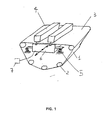
La
L'installation suivant l'invention qui permet de produire des nappes fibreuses non tissées sans marque par brouillage du lignage comprend un convoyeur 1 sans fin passant sur des rouleaux 2 et comportant un brin 3 supérieur sur lequel passe une nappe fibreuse non tissée (non représentée) dont il convient de mieux enchevêtrer les fibres. A cet effet, il est prévu deux bancs 4 d'injecteurs fournissant.des jets d'eau sous 300 bars d'un diamètre de 120 µ. Ces jets sont dirigés verticalement sur la nappe 3 et dans la partie à l'aplomb des injecteurs 4 il y a cinquante jets par centimètre de la nappe. En dessous du brin 3, et en regard de l'injecteur 4, est monté sur ressort 5 un caisson 6 communiquant avec une source 7 de vide. Le caisson est animé, par des moyens représentés à la
Le mouvement d'oscillation est obtenu par un dispositif à bielle 8 et manivelle 9 entraîné en rotation par un moteur qui n'est pas représenté.The oscillation movement is obtained by a connecting rod device 8 and crank 9 rotated by a motor which is not shown.
Bien entendu, on pourrait utiliser d'autres moyens pour donner au caisson un mouvement d'oscillation par exemple un vibrateur rotatif, un vibrateur linéaire à piston ou un mécanisme à excentrique.Of course, other means could be used to give the box an oscillation movement, for example a rotary vibrator, a linear piston vibrator or an eccentric mechanism.
A la
Claims (12)
- Installation for producing nonwoven fibrous webs, that includes a conveyor (1) along a side (3) of which a nonwoven fibrous web passes beneath an injector (4) which blasts the web with water jets appropriate for entangling it, characterized by a means (8, 9) intended to give the conveyor (1) an oscillatory movement (F) at least partly transverse with respect to the direction in which the side (3) runs.
- Installation according to Claim 1, characterized in that the means is designed to impart the oscillatory movement on a return roll (10) of the conveyor (1).
- Installation according to Claim 1, characterized in that the fibrous web passes between the injector (4) and a box (6) communicating with a vacuum source (7) and the means (8, 9) is designed so as to impart the oscillatory movement on the box (6).
- Installation according to one of Claims 1 to 3, characterized by an oscillation amplitude of 0.2 to 5 mm.
- Installation according to one of Claims 1 to 4 or 2, characterized by a number of oscillatory movements of 5 to 100 per second.
- Installation according to one of the preceding claims, characterized by a frequency in Hz of the oscillatory movement representing from 2 to 20 times the speed of the web in m/min.
- Installation according to one of the preceding claims, characterized by a web speed of between 5 and 50 m/min.
- Installation according to one of the preceding claims, characterized by a jet pressure of between 20 and 600 bar.
- Installation according to one of the preceding claims, characterized by a number of jets of between 12 and 77 jets per centimetre on that part of the web facing the injector.
- Installation according to one of Claims 3 to 9, characterized in that the box (6) is mounted so as to be suspended on elastic means (5).
- Installation according to one of Claims 3 to 9, characterized in that one and the same box is associated with several injectors.
- Installation according to one of the preceding claims, characterized by cylindrical jets having a diameter of between 80 and 170 microns.
Applications Claiming Priority (3)
| Application Number | Priority Date | Filing Date | Title |
|---|---|---|---|
| FR0100526A FR2819527B1 (en) | 2001-01-16 | 2001-01-16 | INSTALLATION FOR PRODUCING NON-WOVEN FIBROUS TABLECLOTS BY FLUID JETS WITHOUT VISIBLE MARK |
| FR0100526 | 2001-01-16 | ||
| PCT/FR2001/003250 WO2002055777A1 (en) | 2001-01-16 | 2001-10-19 | Installation for producing non-woven textile webs with jet fluids leaving no visible mark |
Publications (2)
| Publication Number | Publication Date |
|---|---|
| EP1364087A1 EP1364087A1 (en) | 2003-11-26 |
| EP1364087B1 true EP1364087B1 (en) | 2008-07-23 |
Family
ID=8858861
Family Applications (1)
| Application Number | Title | Priority Date | Filing Date |
|---|---|---|---|
| EP01980607A Expired - Lifetime EP1364087B1 (en) | 2001-01-16 | 2001-10-19 | Installation for producing non-woven textile webs with jet fluids leaving no visible mark |
Country Status (7)
| Country | Link |
|---|---|
| US (1) | US7178210B2 (en) |
| EP (1) | EP1364087B1 (en) |
| AT (1) | ATE402282T1 (en) |
| DE (1) | DE60135025D1 (en) |
| ES (1) | ES2307658T3 (en) |
| FR (1) | FR2819527B1 (en) |
| WO (1) | WO2002055777A1 (en) |
Families Citing this family (4)
| Publication number | Priority date | Publication date | Assignee | Title |
|---|---|---|---|---|
| WO2007112441A2 (en) * | 2006-03-28 | 2007-10-04 | North Carolina State University | System and method for reducing jet streaks in hydroentangled fibers |
| CN112041495B (en) | 2018-05-25 | 2023-01-31 | 宝洁公司 | Method for producing a nonwoven and device suitable for the method |
| EP3802939A1 (en) | 2018-05-25 | 2021-04-14 | The Procter & Gamble Company | Nonwoven, and process and apparatus for producing the same |
| CN109487442B (en) * | 2018-11-30 | 2023-11-10 | 山东昌诺新材料科技有限公司 | Water needling head for swinging type positive and negative horizontal belt type water needling machine |
Family Cites Families (23)
| Publication number | Priority date | Publication date | Assignee | Title |
|---|---|---|---|---|
| US3214819A (en) * | 1961-01-10 | 1965-11-02 | Method of forming hydrauligally loomed fibrous material | |
| US3620903A (en) * | 1962-07-06 | 1971-11-16 | Du Pont | Lightweight nonpatterned nonwoven fabric |
| US3508308A (en) * | 1962-07-06 | 1970-04-28 | Du Pont | Jet-treatment process for producing nonpatterned and line-entangled nonwoven fabrics |
| US3493462A (en) * | 1962-07-06 | 1970-02-03 | Du Pont | Nonpatterned,nonwoven fabric |
| DE1635634A1 (en) * | 1965-03-11 | 1970-07-16 | Klaus Sievers | Method and device for the production of needle felts |
| US3434188A (en) * | 1967-01-06 | 1969-03-25 | Du Pont | Process for producing nonwoven fabrics |
| DE2148327A1 (en) * | 1971-09-28 | 1973-04-12 | Freudenberg Carl Fa | Perforated fleece mfr - esp thermoplastic fleece with exceptional strength characteristics |
| US3906599A (en) * | 1972-01-28 | 1975-09-23 | Fiberwoven Corp | Method for producing a needled fabric having improved fiber entanglement |
| JPS526381B2 (en) * | 1972-07-25 | 1977-02-22 | ||
| US3833438A (en) * | 1972-08-30 | 1974-09-03 | Asahi Chemical Ind | Process for the manufacture of a non-woven web of continuous filaments through the wet stretch spinning method |
| DE2530499C3 (en) * | 1975-07-09 | 1978-05-24 | Akzo Gmbh, 5600 Wuppertal | Mat sheet and process for its manufacture |
| DE2540852C3 (en) * | 1975-09-13 | 1978-03-09 | Hoechst Ag, 6000 Frankfurt | Method and additional device for textile drying machines for uniform drying of a textile web |
| DE2950014A1 (en) * | 1979-12-12 | 1981-06-19 | Bayer Ag, 5090 Leverkusen | METHOD AND DEVICE FOR A WASHING PROCESS AFTER SPINDING OF CHEMICAL FIBERS |
| JPS599279A (en) * | 1982-07-07 | 1984-01-18 | 東レ株式会社 | Aniline-like artificial leather and production thereof |
| US4647490A (en) * | 1983-05-20 | 1987-03-03 | Johnson & Johnson | Cotton patterned fabric |
| FR2601970B1 (en) * | 1986-07-24 | 1988-10-28 | Vuillaume Andre | DEVICE FOR MANUFACTURING NONWOVEN FABRICS HAVING HIGH STRENGTH CHARACTERISTICS. |
| US4765100A (en) * | 1987-05-13 | 1988-08-23 | Cookeville Uniform Rental, Inc. | Method of abrading new garments |
| EP0491383B1 (en) * | 1990-12-19 | 1997-08-27 | Mitsubishi Paper Mills, Ltd. | Nonwoven fabric and production method thereof |
| JP3657700B2 (en) * | 1996-06-18 | 2005-06-08 | 新日本石油化学株式会社 | Method for producing high-quality nonwoven fabric |
| US6442809B1 (en) * | 1997-12-05 | 2002-09-03 | Polymer Group, Inc. | Fabric hydroenhancement method and equipment for improved efficiency |
| DE19828118A1 (en) * | 1998-06-24 | 1999-12-30 | Fleissner Maschf Gmbh Co | Device with a nozzle bar for generating liquid jets for the jet interlacing of fibers on a textile web |
| CA2430072A1 (en) * | 2000-11-29 | 2002-06-06 | Polymer Group Inc. | Method for forming laminate nonwoven fabric |
| US6592713B2 (en) * | 2000-12-18 | 2003-07-15 | Sca Hygiene Products Ab | Method of producing a nonwoven material |
-
2001
- 2001-01-16 FR FR0100526A patent/FR2819527B1/en not_active Expired - Fee Related
- 2001-10-19 DE DE60135025T patent/DE60135025D1/en not_active Expired - Lifetime
- 2001-10-19 US US10/470,404 patent/US7178210B2/en not_active Expired - Lifetime
- 2001-10-19 WO PCT/FR2001/003250 patent/WO2002055777A1/en active IP Right Grant
- 2001-10-19 EP EP01980607A patent/EP1364087B1/en not_active Expired - Lifetime
- 2001-10-19 AT AT01980607T patent/ATE402282T1/en not_active IP Right Cessation
- 2001-10-19 ES ES01980607T patent/ES2307658T3/en not_active Expired - Lifetime
Also Published As
| Publication number | Publication date |
|---|---|
| FR2819527B1 (en) | 2003-03-21 |
| DE60135025D1 (en) | 2008-09-04 |
| FR2819527A1 (en) | 2002-07-19 |
| US7178210B2 (en) | 2007-02-20 |
| ATE402282T1 (en) | 2008-08-15 |
| ES2307658T3 (en) | 2008-12-01 |
| EP1364087A1 (en) | 2003-11-26 |
| US20040111847A1 (en) | 2004-06-17 |
| WO2002055777A1 (en) | 2002-07-18 |
Similar Documents
| Publication | Publication Date | Title |
|---|---|---|
| EP0776391B1 (en) | Process for fabricating a pattern-free non woven textile lap by pressure water jets, and plant for implementing such process | |
| EP1407065B1 (en) | Method and device for producing a textile web by spreading tows | |
| EP0772705B1 (en) | Apparatus for producing fluid jet-bonded non-woven webs | |
| EP1364087B1 (en) | Installation for producing non-woven textile webs with jet fluids leaving no visible mark | |
| WO2003100148A1 (en) | Method and system for the manufacture of annular fibrous preforms | |
| EP1812638B1 (en) | Drum for an entanglement machine for a non-woven using water jets | |
| FR2601970A1 (en) | Device for manufacturing non-wovens having high strength characteristics | |
| EP0400249A1 (en) | Apparatus for perforating a web | |
| EP1397546B1 (en) | Circular needling loom with smooth table | |
| EP0452163B1 (en) | Method for treating textile materials by high pressure jets | |
| FI111742B (en) | cleaning device | |
| FR2838457A1 (en) | Production of nonwovens has a conveyor to carry the spunbond filaments to a perforated drum with inner suction, and external pressure water sprays, to give isotropic nonwovens | |
| EP0796363B1 (en) | Needle loom with a sliding shank | |
| EP1190132B1 (en) | Device for treating sheet materials using pressurised water jets | |
| FR2663961A1 (en) | Needling method and machine for carrying it out, especially for short mineral fibres | |
| WO2006084987A1 (en) | Card and machine for the production of a non-woven fabric | |
| FR2806426A1 (en) | INSTALLATION FOR THE PRODUCTION OF NONWOVEN TABLECLOTHS WHICH COHESION IS OBTAINED BY THE ACTION OF FLUID JETS | |
| EP1408148B1 (en) | Process and installation for producing a nonwoven having good tensile strength properties | |
| FR2794144A1 (en) | PROCESS FOR THE MANUFACTURE OF A NEEDLE CARPET | |
| EP1682713B1 (en) | Machine for the production of a finished non-woven | |
| BE629205A (en) | ||
| SU707778A1 (en) | Apparatus for controlling the oscillation of abrasive belt | |
| FR2886653A3 (en) | Needling machine for joining fleece layers, comprising two eccenters positioned above each other and to be rotated in opposite directions | |
| FR2475074A2 (en) | PROCESS AND APPARATUS FOR PRODUCING FIBER NAPPES | |
| CH508762A (en) | Manufacturing process of a non-woven net |
Legal Events
| Date | Code | Title | Description |
|---|---|---|---|
| PUAI | Public reference made under article 153(3) epc to a published international application that has entered the european phase |
Free format text: ORIGINAL CODE: 0009012 |
|
| 17P | Request for examination filed |
Effective date: 20030818 |
|
| AK | Designated contracting states |
Kind code of ref document: A1 Designated state(s): AT BE CH CY DE DK ES FI FR GB GR IE IT LI LU MC NL PT SE TR |
|
| AX | Request for extension of the european patent |
Extension state: AL LT LV MK RO SI |
|
| 17Q | First examination report despatched |
Effective date: 20070419 |
|
| GRAP | Despatch of communication of intention to grant a patent |
Free format text: ORIGINAL CODE: EPIDOSNIGR1 |
|
| GRAS | Grant fee paid |
Free format text: ORIGINAL CODE: EPIDOSNIGR3 |
|
| GRAA | (expected) grant |
Free format text: ORIGINAL CODE: 0009210 |
|
| AK | Designated contracting states |
Kind code of ref document: B1 Designated state(s): AT BE CH CY DE DK ES FI FR GB GR IE IT LI LU MC NL PT SE TR |
|
| REG | Reference to a national code |
Ref country code: GB Ref legal event code: FG4D Free format text: NOT ENGLISH |
|
| REG | Reference to a national code |
Ref country code: CH Ref legal event code: NV Representative=s name: E. BLUM & CO. AG PATENT- UND MARKENANWAELTE VSP Ref country code: CH Ref legal event code: EP |
|
| REG | Reference to a national code |
Ref country code: IE Ref legal event code: FG4D Free format text: LANGUAGE OF EP DOCUMENT: FRENCH |
|
| REF | Corresponds to: |
Ref document number: 60135025 Country of ref document: DE Date of ref document: 20080904 Kind code of ref document: P |
|
| REG | Reference to a national code |
Ref country code: ES Ref legal event code: FG2A Ref document number: 2307658 Country of ref document: ES Kind code of ref document: T3 |
|
| NLV1 | Nl: lapsed or annulled due to failure to fulfill the requirements of art. 29p and 29m of the patents act | ||
| PG25 | Lapsed in a contracting state [announced via postgrant information from national office to epo] |
Ref country code: NL Free format text: LAPSE BECAUSE OF FAILURE TO SUBMIT A TRANSLATION OF THE DESCRIPTION OR TO PAY THE FEE WITHIN THE PRESCRIBED TIME-LIMIT Effective date: 20080723 Ref country code: PT Free format text: LAPSE BECAUSE OF FAILURE TO SUBMIT A TRANSLATION OF THE DESCRIPTION OR TO PAY THE FEE WITHIN THE PRESCRIBED TIME-LIMIT Effective date: 20081223 |
|
| PGFP | Annual fee paid to national office [announced via postgrant information from national office to epo] |
Ref country code: CH Payment date: 20081015 Year of fee payment: 8 |
|
| PG25 | Lapsed in a contracting state [announced via postgrant information from national office to epo] |
Ref country code: FI Free format text: LAPSE BECAUSE OF FAILURE TO SUBMIT A TRANSLATION OF THE DESCRIPTION OR TO PAY THE FEE WITHIN THE PRESCRIBED TIME-LIMIT Effective date: 20080723 |
|
| PGFP | Annual fee paid to national office [announced via postgrant information from national office to epo] |
Ref country code: AT Payment date: 20081015 Year of fee payment: 8 |
|
| REG | Reference to a national code |
Ref country code: IE Ref legal event code: FD4D |
|
| BERE | Be: lapsed |
Owner name: RIETER PERFOJET Effective date: 20081031 |
|
| PG25 | Lapsed in a contracting state [announced via postgrant information from national office to epo] |
Ref country code: IE Free format text: LAPSE BECAUSE OF FAILURE TO SUBMIT A TRANSLATION OF THE DESCRIPTION OR TO PAY THE FEE WITHIN THE PRESCRIBED TIME-LIMIT Effective date: 20080723 Ref country code: DK Free format text: LAPSE BECAUSE OF FAILURE TO SUBMIT A TRANSLATION OF THE DESCRIPTION OR TO PAY THE FEE WITHIN THE PRESCRIBED TIME-LIMIT Effective date: 20080723 |
|
| PG25 | Lapsed in a contracting state [announced via postgrant information from national office to epo] |
Ref country code: MC Free format text: LAPSE BECAUSE OF NON-PAYMENT OF DUE FEES Effective date: 20081031 |
|
| PLBE | No opposition filed within time limit |
Free format text: ORIGINAL CODE: 0009261 |
|
| STAA | Information on the status of an ep patent application or granted ep patent |
Free format text: STATUS: NO OPPOSITION FILED WITHIN TIME LIMIT |
|
| GBPC | Gb: european patent ceased through non-payment of renewal fee |
Effective date: 20081023 |
|
| 26N | No opposition filed |
Effective date: 20090424 |
|
| PG25 | Lapsed in a contracting state [announced via postgrant information from national office to epo] |
Ref country code: BE Free format text: LAPSE BECAUSE OF NON-PAYMENT OF DUE FEES Effective date: 20081031 |
|
| PG25 | Lapsed in a contracting state [announced via postgrant information from national office to epo] |
Ref country code: GB Free format text: LAPSE BECAUSE OF NON-PAYMENT OF DUE FEES Effective date: 20081023 |
|
| PG25 | Lapsed in a contracting state [announced via postgrant information from national office to epo] |
Ref country code: SE Free format text: LAPSE BECAUSE OF FAILURE TO SUBMIT A TRANSLATION OF THE DESCRIPTION OR TO PAY THE FEE WITHIN THE PRESCRIBED TIME-LIMIT Effective date: 20081023 |
|
| REG | Reference to a national code |
Ref country code: CH Ref legal event code: PL |
|
| PG25 | Lapsed in a contracting state [announced via postgrant information from national office to epo] |
Ref country code: CY Free format text: LAPSE BECAUSE OF FAILURE TO SUBMIT A TRANSLATION OF THE DESCRIPTION OR TO PAY THE FEE WITHIN THE PRESCRIBED TIME-LIMIT Effective date: 20080723 Ref country code: LU Free format text: LAPSE BECAUSE OF NON-PAYMENT OF DUE FEES Effective date: 20081019 |
|
| PG25 | Lapsed in a contracting state [announced via postgrant information from national office to epo] |
Ref country code: AT Free format text: LAPSE BECAUSE OF NON-PAYMENT OF DUE FEES Effective date: 20091019 Ref country code: TR Free format text: LAPSE BECAUSE OF FAILURE TO SUBMIT A TRANSLATION OF THE DESCRIPTION OR TO PAY THE FEE WITHIN THE PRESCRIBED TIME-LIMIT Effective date: 20080723 |
|
| PG25 | Lapsed in a contracting state [announced via postgrant information from national office to epo] |
Ref country code: CH Free format text: LAPSE BECAUSE OF NON-PAYMENT OF DUE FEES Effective date: 20091031 Ref country code: GR Free format text: LAPSE BECAUSE OF FAILURE TO SUBMIT A TRANSLATION OF THE DESCRIPTION OR TO PAY THE FEE WITHIN THE PRESCRIBED TIME-LIMIT Effective date: 20081024 Ref country code: LI Free format text: LAPSE BECAUSE OF NON-PAYMENT OF DUE FEES Effective date: 20091031 |
|
| REG | Reference to a national code |
Ref country code: FR Ref legal event code: PLFP Year of fee payment: 15 |
|
| REG | Reference to a national code |
Ref country code: FR Ref legal event code: PLFP Year of fee payment: 16 |
|
| REG | Reference to a national code |
Ref country code: FR Ref legal event code: PLFP Year of fee payment: 17 |
|
| REG | Reference to a national code |
Ref country code: FR Ref legal event code: PLFP Year of fee payment: 18 |
|
| PGFP | Annual fee paid to national office [announced via postgrant information from national office to epo] |
Ref country code: ES Payment date: 20201224 Year of fee payment: 20 Ref country code: FR Payment date: 20201021 Year of fee payment: 20 Ref country code: DE Payment date: 20201022 Year of fee payment: 20 Ref country code: IT Payment date: 20201026 Year of fee payment: 20 |
|
| REG | Reference to a national code |
Ref country code: DE Ref legal event code: R071 Ref document number: 60135025 Country of ref document: DE |
|
| REG | Reference to a national code |
Ref country code: ES Ref legal event code: FD2A Effective date: 20220126 |
|
| PG25 | Lapsed in a contracting state [announced via postgrant information from national office to epo] |
Ref country code: ES Free format text: LAPSE BECAUSE OF EXPIRATION OF PROTECTION Effective date: 20211020 |