EP1363461A2 - Processing of digital images - Google Patents
Processing of digital images Download PDFInfo
- Publication number
- EP1363461A2 EP1363461A2 EP03009671A EP03009671A EP1363461A2 EP 1363461 A2 EP1363461 A2 EP 1363461A2 EP 03009671 A EP03009671 A EP 03009671A EP 03009671 A EP03009671 A EP 03009671A EP 1363461 A2 EP1363461 A2 EP 1363461A2
- Authority
- EP
- European Patent Office
- Prior art keywords
- mean
- correction
- level
- channel
- pixels
- Prior art date
- Legal status (The legal status is an assumption and is not a legal conclusion. Google has not performed a legal analysis and makes no representation as to the accuracy of the status listed.)
- Withdrawn
Links
Images




Classifications
-
- G—PHYSICS
- G06—COMPUTING OR CALCULATING; COUNTING
- G06T—IMAGE DATA PROCESSING OR GENERATION, IN GENERAL
- G06T5/00—Image enhancement or restoration
- G06T5/90—Dynamic range modification of images or parts thereof
- G06T5/92—Dynamic range modification of images or parts thereof based on global image properties
-
- G—PHYSICS
- G06—COMPUTING OR CALCULATING; COUNTING
- G06T—IMAGE DATA PROCESSING OR GENERATION, IN GENERAL
- G06T5/00—Image enhancement or restoration
- G06T5/40—Image enhancement or restoration using histogram techniques
-
- H—ELECTRICITY
- H04—ELECTRIC COMMUNICATION TECHNIQUE
- H04N—PICTORIAL COMMUNICATION, e.g. TELEVISION
- H04N1/00—Scanning, transmission or reproduction of documents or the like, e.g. facsimile transmission; Details thereof
- H04N1/46—Colour picture communication systems
- H04N1/56—Processing of colour picture signals
- H04N1/60—Colour correction or control
- H04N1/6077—Colour balance, e.g. colour cast correction
-
- H—ELECTRICITY
- H04—ELECTRIC COMMUNICATION TECHNIQUE
- H04N—PICTORIAL COMMUNICATION, e.g. TELEVISION
- H04N5/00—Details of television systems
- H04N5/14—Picture signal circuitry for video frequency region
- H04N5/20—Circuitry for controlling amplitude response
-
- G—PHYSICS
- G06—COMPUTING OR CALCULATING; COUNTING
- G06T—IMAGE DATA PROCESSING OR GENERATION, IN GENERAL
- G06T2207/00—Indexing scheme for image analysis or image enhancement
- G06T2207/10—Image acquisition modality
- G06T2207/10024—Color image
-
- H—ELECTRICITY
- H04—ELECTRIC COMMUNICATION TECHNIQUE
- H04N—PICTORIAL COMMUNICATION, e.g. TELEVISION
- H04N23/00—Cameras or camera modules comprising electronic image sensors; Control thereof
- H04N23/80—Camera processing pipelines; Components thereof
- H04N23/84—Camera processing pipelines; Components thereof for processing colour signals
- H04N23/86—Camera processing pipelines; Components thereof for processing colour signals for controlling the colour saturation of colour signals, e.g. automatic chroma control circuits
Definitions
- This invention relates to the manipulation of digital images, in particular to the colour balancing of digital images.
- the proportion of digital images requiring printing or display is growing with the increasing use of digital images in the home, office and on the internet.
- the originating equipment is typically a digital camera or scanner.
- the scene illumination may be less than ideal, resulting in a colour balance error on the final image.
- the colour cast in the original print could give an unacceptable scanned version of the print. Even if the originating equipment provides an accurate 'well balanced' image any subsequent processing may introduce colour casts that need correction.
- the problem with colour balancing digital cameras is that clipped highlights and shadows remain neutral even when the mid-range image data requires colour balancing.
- This invention aims to be able to take any digital image and correct it for colour balance whilst maintaining the neutrality of any highlights or shadows.
- a method of correcting a digital image comprising a plurality of channels, the method comprising the steps of eliminating unrepresentative pixels, measuring the mean level of the remaining pixels for each channel, determining an aim mean for each channel from the measured mean levels, determining a correction level, calculating a power law correction for each channel from the aim mean level and the correction level and applying the power law correction to the input image data to give a corrected output image.
- the unrepresentative pixels are eliminated by means of at least one mask.
- the invention allows any digital image to be colour balanced whilst maintaining neutral shadows and highlights.
- the images can be colour balanced without knowing the source of the image. No operator intervention is required.
- the computer program may be stored in a computer readable storage medium, which may comprise, for example; magnetic storage media such as a magnetic disk (such as a hard drive or a floppy disk) or magnetic tape; optical storage media such as an optical disc, optical tape, or machine readable bar code; solid state electronic storage devices such as random access memory (RAM), or read only memory (ROM); or any other physical device or medium employed to store a computer program.
- a computer readable storage medium may comprise, for example; magnetic storage media such as a magnetic disk (such as a hard drive or a floppy disk) or magnetic tape; optical storage media such as an optical disc, optical tape, or machine readable bar code; solid state electronic storage devices such as random access memory (RAM), or read only memory (ROM); or any other physical device or medium employed to store a computer program.
- the present invention is preferably utilized on any known computer system, such a personal computer. Consequently, the computer system will not be discussed in detail herein. It is also instructive to note that the images are either directly input into the computer system (for example by a digital camera) or digitized before input into the computer system (for example by scanning an original, such as a silver halide film).
- FIG. 1 illustrates the method of the invention.
- the method can be divided into three stages.
- the first stage the analysis of the image data to extract colour balance information, takes place in blocks 1, 2, 3 and 4 in Figure 1.
- the second stage a calculation stage using the extracted information to give a corrected figure, takes place in block 5.
- the third stage the final application of the correction on the image data, takes place in block 6.
- Block 1 the analysis process uses a number of masks to remove unrepresentative pixels from the colour analysis. Typically the masks eliminate pixels which are clipped or which are highly saturated. This is described in more detail below, with respect to Figure 2.
- Block 1 additionally measures the extent of the neutral highlights and shadows and passes the information on to block 6.
- block 2 the mean level of the pixels remaining after the masking of block 1 is measured to obtain a measure of the colour balance of the image.
- a weighting generator generates two spatial weighting functions. These weighting functions are used to weight mean level measurements of the input image toward the centre of the image or toward the periphery of the image. For the colour balance measurement, measured in block 2, the weighting is toward the centre of the image to give a greater bias toward the likely position of the subject of the image.
- These weighting functions although preferred, are not essential to the invention.
- Figure 2 is an expansion of block 1 in Figure 1.
- the input data for analysis is first sub-sampled, in block 7, to reduce the computing time and then low-pass filtered, in block 8, to remove noise.
- the conditioned data i.e. the sub-sampled and filtered data, is then passed to the various masks, blocks 9, 10, 11 and 12, before the mean level analysis, to determine the colour balance of the image.
- An edge inclusion mask is generated, in block 9, in order to measure the mean level of just the edge pixels, i.e where detail is found in the image. This eliminates uniform areas of the image from the measurement.
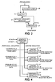
- Figure 3 is an expansion of block 9.
- the output from block 8 is further low pass filtered in block 18.
- a low pass filtered version of the analysis data is subtracted from itself and generates a high pass filtered signal.
- the standard deviation of the high pass filtered signal is measured in block 20. This standard deviation is used to set an adaptive threshold for the generation of the edge detail mask in block 21.
- a scaling factor, 'Scale' in equation 1, for the standard deviation can be set to optimise the resulting mask. This could, for example, be 0.5.
- EdgeMask 1 when
- a highlight exclusion mask is generated in block 10.
- This highlight exclusion mask eliminates triply clipped and near triply clipped pixels from the analysis. These pixels will always be neutral and can only detract from the colour measurement. The mask is true if all three channels are above the white threshold.
- the minimum code value for which the highlights are neutral is set empirically. Generally it will be maximum digital data value, and this value will be used in the implementation block, block 6. Peculiar to digital camera images is the possibility that the camera processing has already made the shadows neutral. This is not true of all digital cameras but if the shadows are already neutral the colour balancing process of the present invention should not make them coloured.
- a shadow exclusion mask is generated in block 11. This shadow exclusion mask detects the neutral shadows and eliminates those pixels from the analysis.
- the maximum code value for which the shadows are neutral is determined, generally it will be the data minimum value. This value is typically zero but may go up to 20, for example, in an 8 bit system. This value will be used later in the implementation block, block 6. Together, blocks 10 and 11 determine the neutral levels.
- a third exclusion mask is generated in block 12. This is not essential to the invention but is a preferred feature. This mask eliminates highly saturated areas of the image from the analysis.
- the saturation threshold is adaptive. Equations 2, 3 and 4 below are shown as an example set of equations for deriving the saturation mask. In this example the mask is derived by taking the sum of the absolute differences between an equal weight neutral and each colour, as shown in equations 2 and 3. The maximum level of the saturation from equation 3 is used to set an adaptive threshold for the saturation mask generation, equation 4.
- ) Saturation mask 1 when (
- Neu is the Neutral from equation 2
- Thresh saturation scale factor * maximum saturation from equation 3
- the 'saturation scale factor' is optimised during development. A typical value could, for example, be 0.4.
- the three exclusion masks, from blocks 10, 11 and 12, are combined into a composite exclusion mask in block 17. This mask is then applied to the image data in blocks 13 and 14.
- the mean level of the whole image is measured.
- the mean level of the edge, i.e. detail, of the image is measured.
- the outputs from blocks 13 and 14 are passed to the centre weighted mean level measurement block, block 2 in figure 1, to generate two sets of mean level data, representative of the colour balance of the image.
- the image data for the colour correction level can be optionally masked, by highlight and shadow clip masks, in block 32 before being passed to block 24, for the centre weighted mean level measurement, and block 25 for the peripheral mean level measurement. Blocks 24 and 25 are explained further with respect to figure 4.
- Figure 4 is an expansion of blocks 2 and 3 from Figure 1.
- the weighting functions generated in block 4 are used to generate the weighting plane, using an offset gausian or cosine function.
- An offset level is used to set the peripheral weighting, i.e. the weighting for the periphery of the image, and a scaling factor is used to set the central weighting, i.e. the weighting for the centre of the image.
- the scale could be set to clip the central area to give it a uniform weighting.
- the means for each colour for the edge, i.e detail, masked image are determined using a centre weighted histogram.
- the means for each colour for the whole masked image are determined using a centre weighed histogram. Block 23 is preferable but not essential to the invention.
- the means are a measure of the colour balance of the image and are used to determine the aim mean in the calculation block, block 5.
- the spatial weighting in the histogram varies the equivalent value of a pixel with respect to its position in the image, i.e.
- blocks 24 and 25 the means of the filtered image data, from block 32, are determined using centre weighted histograms (in block 24) and peripheral weighted histograms (in block 25). These means, i.e. the outputs of blocks 24 and 25 are used to determine the colour correction level of the aim means calculated from the outputs of blocks 22 and 23 in the calculation block, block 5.
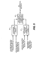
- FIG. 5 is an expansion of block 5 in Figure 1.
- the aim mean level for each colour is determined, using the outputs of blocks 22 and 23 and any preferred colour balance set by parameters, e.g. Red pref and Blue pref .
- the colour correction level is determined using the outputs of blocks 24 and 25.
- the aim mean level and the colour correction level are combined in block 28 to give the power law corrections for the implementation block, block 6, in Figure 1.
- the mean level for each colour channel is comprised of a combination of the edge pixel mean (edgemean) and the masked mean of the whole image (maskedMean). Equation 5 is an example of the calculation used for the red channel. It will be understood that other colour channels would be similarly calculated.
- Aim Average (R mean + G mean + G mean + B mean ) / 4
- Red aim Aim Average * Red pref
- Red pref could for example have a value of 1.05 and Blue pref could have a value of 0.95.
- the colour correction level is calculated in block 27. This sets the level to which the colour means calculated in equation 5 are moved toward the Aim Average from equations 6 or 7. It is set by the difference in mean level between the centre weighted means and the peripheral weighted means for each colour. The difference can be measured in a number of ways. Equation 8 below gives an example based on normalised difference. The level of colour correction is set by the normalised difference between the centre and peripheral means of the image data obtained from blocks 24 and 25. The bigger the difference the lower the correction. The equation is weighted toward green, but it will be understood that any combination could be used to suit the range of images being balanced.
- Figure 6 is an expansion of block 6 of Figure 1.
- the power law correction obtained from block 28 is applied to the input data after removal of the neutral levels and the appropriate colour mask in block 29.
- G out G corrected + G mask * G in + G m ask * n lev Where G in is the green input data, nlev is the neutral level and G mask is the green mask.
- the correction data may be optionally low pass filtered in block 33, to reduce any noise addition or missing codes due to the non-linear nature of the correction. If the correction data is being low pass filtered, then G out , equation 13, is subtracted from the filtered G in to give just the correction data which is then added onto the full band image data in block 30.
- the present invention may be included in a range of applications in which digital images are input, images captured digitally, or film images scanned; digital image processing performed; and digital images output, stored or printed.
- applications include digital processing laboratories (mini and wholesale), kiosks, internet fulfilment, and commercial or home computer systems with appropriate peripherals, digital cameras and so on.
- the computer system 110 includes a microprocessor-based unit 112 for receiving and processing software programs and for performing other processing functions.
- a display 114 is electrically connected to the microprocessor-based unit 112 for displaying user-related information associated with the software, e.g., by means of a graphical user interface.
- a keyboard 116 is also connected to the microprocessor based unit 112 for permitting a user to input information to the software.
- a mouse 118 may be used for moving a selector 120 on the display 114 and for selecting an item on which the selector 120 overlays, as is well known in the art.
- a compact disk-read only memory (CD-ROM) 122 is connected to the microprocessor based unit 112 for receiving software programs and for providing a means of inputting the software programs and other information to the microprocessor based unit 112 via a compact disk 124, which typically includes a software program.
- a floppy disk 126 may also include a software program, and is inserted into the microprocessor-based unit 112 for inputting the software program.
- the microprocessor-based unit 112 may be programmed, as is well known in the art, for storing the software program internally.
- the microprocessor-based unit 112 may also have a network connection 127, such as a telephone line, to an external network, such as a local area network or the Internet.
- a printer 128 is connected to the microprocessor-based unit 112 for printing a hardcopy of the output of the computer system 110. Images may also be displayed on the display 114 via a personal computer card (PC card) 130, such as, as it was formerly known, a PCMCIA card (based on the specifications of the Personal Computer Memory Card International Association) which contains digitized images electronically embodied in the card 130.
- PC card 130 is ultimately inserted into the microprocessor based unit 112 for permitting visual display of the image on the display 114. Images may also be input via the compact disk 124, the floppy disk 126, or the network connection 127.
- any images stored in the PC card 130, the floppy disk 126 or the compact disk 124, or input through the network connection 127 may have been obtained from a variety of sources, such as a digital camera (not shown) or a scanner (not shown).
- the algorithm may be stored in any of the storage devices heretofore mentioned and applied to images in order to colour balance the images.
Landscapes
- Engineering & Computer Science (AREA)
- Multimedia (AREA)
- Signal Processing (AREA)
- Physics & Mathematics (AREA)
- General Physics & Mathematics (AREA)
- Theoretical Computer Science (AREA)
- Image Processing (AREA)
- Facsimile Image Signal Circuits (AREA)
- Color Image Communication Systems (AREA)
- Processing Of Color Television Signals (AREA)
Abstract
Description
The weighting functions generated in
Redpref could for example have a value of 1.05 and Bluepref could have a value of 0.95.
In
Claims (20)
- A method of correcting an input digital image comprising a plurality of channels, the method comprising the steps of eliminating unrepresentative pixels, measuring the mean level of the remaining pixels for each channel, determining an aim mean for each channel from the measured mean levels, determining a correction level, calculating a power law correction for each channel from the aim mean level and the correction level and applying the power law correction to the input image data to give a corrected output image.
- A method as claimed in claim 1 wherein the unrepresentative pixels are eliminated by means of at least one mask.
- A method as claimed in claim 2 wherein an edge pixel mask is used to eliminate uniform areas of the image.
- A method as claimed in claim 2 or 3 wherein a highlight exclusion mask is used to eliminate unrepresentative clipped pixels.
- A method as claimed in claim 2, 3 or 4 wherein a shadow exclusion mask is used to eliminate neutral shadows.
- A method as claimed in claim 2, 3, 4 or 5 wherein an exclusion mask eliminates pixels whose colour saturation is above a pre-set threshold.
- A method as claimed in claim 6 wherein the threshold is adaptive.
- A method as claimed in any of claims 3 to 7 wherein the mean level used to determine the aim mean for each channel is a combination of the mean levels of the pixels remaining after each mask.
- A method as claimed in any of claims 3 to 7 wherein the mean level used to determine the aim mean for each channel comprises a combination of the mean level of the pixels remaining after the exclusion masks and the mean level of the pixels after the application of the edge pixel mask.
- A method as claimed in any of claims 1 to 9 wherein the aim mean comprises a combination of the mean levels of each channel.
- A method as claimed in claim 10 wherein the aim mean is an equally weighted combination of the mean level of each channel.
- A method as claimed in any of claims 1 to 11 wherein the mean level is calculated for both centre weighted pixels and peripheral weighted pixels.
- A method as claimed in claim 12 wherein the correction level is inversely proportional to the difference between the centre weighted mean level to the peripheral weighted mean level.
- A method as claimed in claim 13 wherein the power law correction is calculated from a combination of the mean level for each channel, the aim mean and the correction level.
- A method as claimed in claim 1 wherein the power law correction is applied to the image data after elimination of neutral shadows and highlights, the corrected data and neutral data being recombined to give the corrected output image.
- A method as claimed in claim 1 wherein the input image data is low pass filtered prior to correction, the resulting data being subtracted from the uncorrected filtered data to give filtered correction data, the filtered correction data being added to the input image data to give a final corrected output image.
- A computer program product for correcting a digital image comprising a computer readable storage medium having a computer program stored thereon for performing the steps of eliminating unrepresentative pixels, measuring the mean level of the remaining pixels for each channel, determining an aim mean for each channel from the measured mean levels, determining a correction level, calculating a power law correction for each channel from the aim mean level and the correction level and applying the power law correction to the input image data to give a corrected output image.
- A computer program comprising code means for performing all the steps of any of claims 1 to 16 when said program is run on a computer.
- A device for correcting a digital image comprising a plurality of channels, the apparatus comprising means for eliminating unrepresentative pixels, means for measuring the mean level of the remaining pixels for each channel, means for determining an aim mean for each channel from the measured mean levels, means for determining a correction level, means for calculating a power law correction for each channel and means for applying the power law correction to the input image data to give a corrected output image.
- A system for the processing of digital image data wherein a digital image is input, the image is processed and the processed image stored and/or output, at least part of the processing of the image comprising a method according to any of claims 1 to 16.
Applications Claiming Priority (2)
| Application Number | Priority Date | Filing Date | Title |
|---|---|---|---|
| GBGB0211486.6A GB0211486D0 (en) | 2002-05-18 | 2002-05-18 | Processing of digital images |
| GB0211486 | 2002-05-18 |
Publications (2)
| Publication Number | Publication Date |
|---|---|
| EP1363461A2 true EP1363461A2 (en) | 2003-11-19 |
| EP1363461A3 EP1363461A3 (en) | 2005-11-23 |
Family
ID=9936976
Family Applications (1)
| Application Number | Title | Priority Date | Filing Date |
|---|---|---|---|
| EP03009671A Withdrawn EP1363461A3 (en) | 2002-05-18 | 2003-04-30 | Processing of digital images |
Country Status (4)
| Country | Link |
|---|---|
| US (1) | US7319544B2 (en) |
| EP (1) | EP1363461A3 (en) |
| JP (1) | JP2004030635A (en) |
| GB (1) | GB0211486D0 (en) |
Families Citing this family (5)
| Publication number | Priority date | Publication date | Assignee | Title |
|---|---|---|---|---|
| JP4276113B2 (en) * | 2004-03-05 | 2009-06-10 | Okiセミコンダクタ株式会社 | Standard radio wave reception time device and time code signal decoding method |
| US7848569B2 (en) * | 2005-12-14 | 2010-12-07 | Micron Technology, Inc. | Method and apparatus providing automatic color balancing for digital imaging systems |
| JP5078416B2 (en) * | 2006-04-27 | 2012-11-21 | キヤノン株式会社 | Reflective liquid crystal display device and substrate for reflective liquid crystal display device |
| KR100944595B1 (en) * | 2007-04-24 | 2010-02-25 | 가부시끼가이샤 르네사스 테크놀로지 | Display device, display device driving circuit, image display method, electronic device and image display device driving circuit |
| JP5663564B2 (en) * | 2010-04-20 | 2015-02-04 | 富士フイルム株式会社 | Imaging apparatus, captured image processing method, and captured image processing program |
Family Cites Families (10)
| Publication number | Priority date | Publication date | Assignee | Title |
|---|---|---|---|---|
| US2571697A (en) * | 1946-06-20 | 1951-10-16 | Eastman Kodak Co | Method for correcting photographic color prints |
| JPS5981992A (en) | 1982-11-02 | 1984-05-11 | Canon Inc | color imaging device |
| US4729016A (en) | 1985-05-06 | 1988-03-01 | Eastman Kodak Company | Digital color image processing method and apparatus employing three color reproduction functions for adjusting both tone scale and color balance |
| US4677465A (en) | 1985-11-01 | 1987-06-30 | Eastman Kodak Company | Digital color image processing method with shape correction of histograms used to produce color reproduction functions |
| US4883360A (en) | 1987-08-13 | 1989-11-28 | Fuji Photo Film Co., Ltd. | Method and apparatus for automatically adjusting white balance |
| JPH0787588B2 (en) | 1987-12-29 | 1995-09-20 | 富士写真フイルム株式会社 | Method and device for automatic white balance adjustment |
| US5436734A (en) * | 1991-11-18 | 1995-07-25 | Fuji Xerox Co., Ltd. | Image-edit processing apparatus |
| DE4309877C2 (en) * | 1992-04-06 | 1994-09-15 | Hell Ag Linotype | Method and device for analyzing color casts in color templates |
| US6151410A (en) * | 1996-11-19 | 2000-11-21 | Seiko Epson Corporation | Image processing apparatus, image processing method and medium for storing image-processing control program |
| EP1014695B1 (en) * | 1998-12-23 | 2006-01-11 | Eastman Kodak Company | Correction of colour balance in images |
-
2002
- 2002-05-18 GB GBGB0211486.6A patent/GB0211486D0/en not_active Ceased
-
2003
- 2003-04-30 EP EP03009671A patent/EP1363461A3/en not_active Withdrawn
- 2003-05-13 US US10/437,127 patent/US7319544B2/en not_active Expired - Fee Related
- 2003-05-19 JP JP2003140496A patent/JP2004030635A/en active Pending
Also Published As
| Publication number | Publication date |
|---|---|
| JP2004030635A (en) | 2004-01-29 |
| GB0211486D0 (en) | 2002-06-26 |
| US20030214663A1 (en) | 2003-11-20 |
| EP1363461A3 (en) | 2005-11-23 |
| US7319544B2 (en) | 2008-01-15 |
Similar Documents
| Publication | Publication Date | Title |
|---|---|---|
| US5739922A (en) | Image processing method and apparatus for reducing the effect of image information having perceptible film graininess | |
| US7844127B2 (en) | Edge mapping using panchromatic pixels | |
| US7065255B2 (en) | Method and apparatus for enhancing digital images utilizing non-image data | |
| US7791652B2 (en) | Image processing apparatus, image capture apparatus, image output apparatus, and method and program for these apparatus | |
| US7593570B2 (en) | Image processing method and apparatus and storage medium | |
| US6204940B1 (en) | Digital processing of scanned negative films | |
| US7034878B2 (en) | Camera apparatus and method of taking pictures including simplified processing | |
| JP3011432B2 (en) | Color image processing equipment | |
| US7652717B2 (en) | White balance correction in digital camera images | |
| JPH10187994A (en) | Method for evaluating and controlling digital image contrast | |
| JP2003179756A (en) | Method for processing data from digital image and program product | |
| JP2000050076A (en) | Digital photograph finishing system containing scene- balanced/contrast-normalized/visualized digital picture processing | |
| EP0460193A1 (en) | A method to extend the linear range of images captured on film. | |
| JPH0646448A (en) | Image processing method/device | |
| US6876777B2 (en) | Image enhancement method | |
| JP2002354244A (en) | Method for compensating digital image for light falloff while minimizing light balance change | |
| EP1014695B1 (en) | Correction of colour balance in images | |
| US7319544B2 (en) | Processing of digital images | |
| JP3950551B2 (en) | Image processing method, apparatus, and recording medium | |
| CN112995633B (en) | Image white balance processing method and device, electronic equipment and storage medium | |
| JPH0654195A (en) | System and method for image scanner for improvement of microfilm image quality | |
| US20050140804A1 (en) | Extended dynamic range image sensor capture using an array of fast and slow pixels | |
| US6968081B1 (en) | System, method, and apparatus for orienting images | |
| JP2000013595A (en) | Image processing method, apparatus and recording medium | |
| JPH11205623A (en) | Method and device for processing image |
Legal Events
| Date | Code | Title | Description |
|---|---|---|---|
| PUAI | Public reference made under article 153(3) epc to a published international application that has entered the european phase |
Free format text: ORIGINAL CODE: 0009012 |
|
| AK | Designated contracting states |
Kind code of ref document: A2 Designated state(s): AT BE BG CH CY CZ DE DK EE ES FI FR GB GR HU IE IT LI LU MC NL PT RO SE SI SK TR |
|
| AX | Request for extension of the european patent |
Extension state: AL LT LV MK |
|
| PUAL | Search report despatched |
Free format text: ORIGINAL CODE: 0009013 |
|
| AK | Designated contracting states |
Kind code of ref document: A3 Designated state(s): AT BE BG CH CY CZ DE DK EE ES FI FR GB GR HU IE IT LI LU MC NL PT RO SE SI SK TR |
|
| AX | Request for extension of the european patent |
Extension state: AL LT LV MK |
|
| 17P | Request for examination filed |
Effective date: 20060328 |
|
| AKX | Designation fees paid |
Designated state(s): DE FR GB |
|
| 17Q | First examination report despatched |
Effective date: 20070629 |
|
| STAA | Information on the status of an ep patent application or granted ep patent |
Free format text: STATUS: THE APPLICATION IS DEEMED TO BE WITHDRAWN |
|
| 18D | Application deemed to be withdrawn |
Effective date: 20071110 |