EP1363415A2 - Method of evaluating free-space optical propagation characteristics - Google Patents
Method of evaluating free-space optical propagation characteristics Download PDFInfo
- Publication number
- EP1363415A2 EP1363415A2 EP03252964A EP03252964A EP1363415A2 EP 1363415 A2 EP1363415 A2 EP 1363415A2 EP 03252964 A EP03252964 A EP 03252964A EP 03252964 A EP03252964 A EP 03252964A EP 1363415 A2 EP1363415 A2 EP 1363415A2
- Authority
- EP
- European Patent Office
- Prior art keywords
- laser
- beams
- laser beams
- target point
- spot
- Prior art date
- Legal status (The legal status is an assumption and is not a legal conclusion. Google has not performed a legal analysis and makes no representation as to the accuracy of the status listed.)
- Granted
Links
- 230000003287 optical effect Effects 0.000 title claims abstract description 38
- 238000000034 method Methods 0.000 title claims abstract description 35
- 238000001228 spectrum Methods 0.000 claims abstract description 21
- NJPPVKZQTLUDBO-UHFFFAOYSA-N novaluron Chemical compound C1=C(Cl)C(OC(F)(F)C(OC(F)(F)F)F)=CC=C1NC(=O)NC(=O)C1=C(F)C=CC=C1F NJPPVKZQTLUDBO-UHFFFAOYSA-N 0.000 claims description 5
- 230000033001 locomotion Effects 0.000 description 16
- 238000005259 measurement Methods 0.000 description 10
- 238000004891 communication Methods 0.000 description 8
- 230000000694 effects Effects 0.000 description 8
- 230000005540 biological transmission Effects 0.000 description 3
- 230000007613 environmental effect Effects 0.000 description 3
- 230000001902 propagating effect Effects 0.000 description 3
- 230000003595 spectral effect Effects 0.000 description 3
- 230000009466 transformation Effects 0.000 description 3
- XLYOFNOQVPJJNP-UHFFFAOYSA-N water Chemical compound O XLYOFNOQVPJJNP-UHFFFAOYSA-N 0.000 description 3
- 230000002596 correlated effect Effects 0.000 description 2
- 238000013461 design Methods 0.000 description 2
- 238000002474 experimental method Methods 0.000 description 2
- 230000000644 propagated effect Effects 0.000 description 2
- 208000030984 MIRAGE syndrome Diseases 0.000 description 1
- 238000004458 analytical method Methods 0.000 description 1
- 238000013459 approach Methods 0.000 description 1
- 238000005452 bending Methods 0.000 description 1
- 238000001514 detection method Methods 0.000 description 1
- 238000011161 development Methods 0.000 description 1
- 230000008030 elimination Effects 0.000 description 1
- 238000003379 elimination reaction Methods 0.000 description 1
- 238000005516 engineering process Methods 0.000 description 1
- 238000011156 evaluation Methods 0.000 description 1
- 239000007789 gas Substances 0.000 description 1
- 239000011521 glass Substances 0.000 description 1
- 238000000691 measurement method Methods 0.000 description 1
- 238000012545 processing Methods 0.000 description 1
- 238000000926 separation method Methods 0.000 description 1
- 238000006467 substitution reaction Methods 0.000 description 1
- 230000001360 synchronised effect Effects 0.000 description 1
- 230000002123 temporal effect Effects 0.000 description 1
- 239000012780 transparent material Substances 0.000 description 1
- 238000001845 vibrational spectrum Methods 0.000 description 1
Images


Classifications
-
- H—ELECTRICITY
- H04—ELECTRIC COMMUNICATION TECHNIQUE
- H04B—TRANSMISSION
- H04B10/00—Transmission systems employing electromagnetic waves other than radio-waves, e.g. infrared, visible or ultraviolet light, or employing corpuscular radiation, e.g. quantum communication
- H04B10/11—Arrangements specific to free-space transmission, i.e. transmission through air or vacuum
- H04B10/112—Line-of-sight transmission over an extended range
- H04B10/1123—Bidirectional transmission
- H04B10/1125—Bidirectional transmission using a single common optical path
Definitions
- the present invention relates to a method of evaluating free-space optical propagation characteristics for improving the quality of optical communications in free space.
- Free-space optical communication between adjacent buildings uses a transmitter that transmits an optical signal in the form of a modulated laser beam, and a receiver that receives the optical signal. Between the transmitter and the receiver are transparent gases, such as the atmospheric air and water vapor in the air, transparent materials, such as glass, and mirrors and the like that reflect the optical signal.
- transparent gases such as the atmospheric air and water vapor in the air
- transparent materials such as glass, and mirrors and the like that reflect the optical signal.
- the advantage of this method is that it enables a high-speed communications route to be established using simple system equipment.
- this method has a number of drawbacks when it comes to long-range, line-of-sight communication between points in free space.
- the transmitter is usually attached to a building, so when the building sways, the transmitter also sways, causing the laser beam spot to fluctuate.
- the fluctuation of the beam spot becomes quite pronounced.
- the movement of an object can be divided into parallel and rotational motion components.
- the parallel component has no distance dependency, but the rotational component increases with the increase in the distance of the beam propagation, which can cause the beam to miss the receiver.
- the emission angle of the laser beam can be increased to prevent this happening, doing so creates wave-front turbulence that restricts transmission speeds.
- Figure 1 shows how the traveling direction of a laser beam launched from a transmitter to a receiver is altered by changes in the refraction index distribution of the atmosphere caused by air currents and the like. This bending of the laser beam and movement of the beam spot at the point of reception is called spot-dancing. In the case of a propagation distance of several kilometers, the fluctuation of the beam at the receiving point can be as much as several meters, so when the beam has a very small diameter, it can miss the receiver aperture, interrupting the optical link.
- a technique used to reduce spot-dancing is to provide the transmitter and receiver with a beam-tracking function.
- a beam-tracking system functions by, at the receiving end, detecting deviation of the laser beam from the optimum receiving position, based on which, at the transmission end, the beam direction is adjusted accordingly.
- Spot-dancing characteristics are important in optimizing the design of the tracking system.
- Figure 2 shows a method of observing spot-dancing by projecting an atmospherically propagated optical beam on a screen and using a camera to observe the spot.
- the beam-spot position on the screen fluctuates due to both atmospheric turbulence and building/transmitter vibration.
- this method cannot be used to isolate the extent of the effect of atmospheric turbulence.
- the effects of atmospheric turbulence and building/transmitter vibration could be differentiated, it would be useful in many ways. For example, if the effect of building/transmitter vibration was large, the transmitter location or setup could be changed. If the effect of atmospheric turbulence was large, the design of the tracking system could be optimized to make it more generally applicable.
- the drawback of free-space optical communications is that it is subject to the effect of building variations and changes in the environment of the propagation path.
- an object of the present invention is to provide a method of evaluating free-space optical propagation characteristics Lhat distinguishes between optical propagation path changes due to transmitter vibration and those due to environmental changes.
- the present invention provides a method of evaluating free-space optical propagation characteristics, comprising the steps of emitting a plurality of laser beams from a respective plurality of laser sources, receiving respective laser beams at a first target point and a second target point and reading time-based spatial fluctuations between the laser beams received at the first and second target points, using a first distance from a first laser source to the first target point and a second distance from a second laser source to the second target point to normalize the time-based spatial fluctuations, deriving a difference between a normalized spatial position of a laser beam at the first target point and a normalized spatial position of a laser beam at the second target point, and obtaining a frequency spectrum of time-based fluctuations of the derived spatial positions.
- the method also includes at least two of the plurality of emitted laser beams being beams traveling in opposite directions or emitted in parallel.
- the method also includes at least two of the plurality of emitted laser beams being beams emitted from two laser sources affixed to the same pedestal.
- the method further comprises the steps of using optical scatterers to scatter each of the laser beams at the first and second target points, using an image-forming system to form an image of the scattered laser beams, and receiving light of the image formed.
- the method also includes at least one of the plurality of emitted laser beams being a pulsed laser beam, and the pulsed laser beam being received by a receiver that operates in synchronization with pulses of the laser beam.
- the evaluation method of the present invention makes it possible to simultaneously distinguish optical propagation path changes due to transmitter vibration from those due to environmental factors.
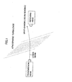
- Figure 3 shows a method for measuring atmospheric spot-dancing characteristics, using two laser beams in a system that includes points A, B and C.
- One laser beam is propagated from A to B and the other laser beam from A to C. It is assumed that the two laser sources at point A are fixed on a pedestal having a sufficiently high stiffness, with the pedestal being attached to a building.
- Figure 4 shows the arrangement more specifically.
- a laser beam is emitted from a laser source 1a atop of a building 30 and propagates along a path 11 to fall incident onto a receiver 2a, atop of a building 31, having a two-dimensional optical detector. Having received the laser beam, the receiver 2a sends information on the position of the beam to a data processor (not shown).
- a laser beam emitted from a laser source 1b propagates along a path 12 to fall incident onto a receiver 2b, atop of a building 32, having a two-dimensional optical detector, causing information on the position of the beam thus received to be sent to the data processor
- the laser sources 1a and 1b are near-infrared sources, since most free-space communication systems use near-infrared light.
- a special apparatus is required to make near-infrared light visible, so for visibility, red light can also be added.
- the vibration of the building at point A can be assumed to have the same affect on the beam propagating from A to C and on the beam propagating from A to B. That is, assuming the arrangement is viewed from above, if the building on which point A is located twists to the right, the beam spots at points B and C will also move to the right, and the amount of such movement will be proportional to the distance between A and B and the distance between A and C.
- the horizontal and vertical components of the movement of the beam spots projected on screens perpendicular to the beams at B and C are expressed as (x 1 , y 1 ) and (x 2 , y 2 ), respectively.
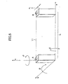
- the abc Cartesian coordinate system shown in Figure 5 is used to express the building motions.
- the beam 11 launched from point A to point B is parallel to the a-axis.
- l 1 expresses the distance the beam travels between A and B.
- Movement of the laser source due to building vibration has six degrees of freedom, which are: shifts parallel to a, b and c and twists ⁇ , ⁇ and ⁇ .
- beam-spot movement can be expressed using the functions f 1 , g 1 , f 2 , g 2 , as follows.
- x 1 f 1 (a, b, c, ⁇ , ⁇ , ⁇ , t)
- y 1 g 1 (a, b, c, ⁇ , ⁇ , ⁇ , t)
- x 2 f 2 (a, b, c, ⁇ , ⁇ , ⁇ , t)
- y 2 g 2 (a, b, c, ⁇ , ⁇ , ⁇ , t)
- Equation 3 over-primary terms express the building vibration component of the beam-spot movement.
- the effect of the over-secondary terms is disregarded, since they are small compared to the primary terms.
- this type of approximation can be considered valid.
- Equation 3 becomes as shown in Equation 5.
- f 1 (a, b, c, ⁇ , ⁇ , ⁇ , t) ⁇ f 1 (0, 0, 0, 0, 0, L) + Df 1 (0, 0, 0, 0, 0, 0, t) f 1 (0, 0, 0, 0, 0, 0, t) + a ⁇ f 1 (0,0,0,0,0,0, t ) ⁇ a + b ⁇ f 1 (0,0,0,0,0,0, t ) ⁇ b + c ⁇ f 1 (0,0,0,0,0,0,0, t ) ⁇ c + ⁇ ⁇ f 1 (0,0,0,0,0,0,0, t ) ⁇ ⁇ + ⁇ ⁇ f 1 (0,0,0,0,0,0, t ) ⁇ ⁇ + ⁇ ⁇ f 1 (0,0,0,0,0,0, t ) ⁇ ⁇ + ⁇ ⁇ f 1 (0,0,0,0,0,0, t )
- Equation 6 can be derived from the geometrical relationship of the points AB in the coordinate system.
- Equation 7 The f 1 approximation of Equation 7 can be derived through substitution of Equation 6 for Equation 5.
- Equation 8 is obtained by performing the same type of approximation in respect of g 1 .
- Equation 2 how to handle the beam-spot function (Equation 2) at point C in Figure 3 changes depending on the relationship among A, B and C. Below, the approximation of Equation 2 when the cases are divided into the following three is described, together with the method of eliminating the building vibration component.
- Equation 2 can be used for the approximations of Equations 9 and 10. x 2 ⁇ f 2 (0, 0, 0, 0, 0, 0, t) + b - l 2 ⁇ y 2 ⁇ g 2 (0, 0, 0, 0, 0, 0, t) + c + l 1 ⁇
- Equations 7 to 10 the building vibration component terms including l 1 and l 2 dominate because even a minute twist of the building is amplified at the point of arrival, causing major movement of the beam-spot.
- the horizontal building shift components b and c are usually small movements in the order of a few millimeters, and as such pose no problem in practice. Therefore, vibration components caused by building twist can be cancelled by obtaining x and y of Equations 11 and 12.
- Equation 11 the characteristic difference in atmospheric turbulence between the two beam routes AB and AC was negligible. If, for example, the beam AB passes over a river and the beam AC does not, there would likely be some characteristic difference in the atmospheric turbulence between the routes. Changes in the spectral distribution can be calculated as in Equations 11 and 12. The same kind of measurement described above can be performed in this case by launching two parallel beams from A to B apart from each other, denoted in Figure 7 as beams 11a and 11b. Since x 1 and x 2 , and y 1 and y 2 , have the same building vibration component, they can be subtracted to obtain Equation 13.
- the distance between the beams is one meter, for example, the two beam-spots are moved similarly by atmospheric turbulence that fluctuates with d volume size smaller than one meter (that is, the wavelength of the spatial frequency is one meter or less), so the components of that atmospheric turbulence can be cancelled by the operations of Equations 13 and 14.
- the advantage of this method of measurement is that, because of the closeness of the beam-spots at point B, the two beam spots can be observed using one camera, resulting in a simplified measurement system.
- the drawback of the above method (2) is that the two beams have to be separated by an amount that is larger than the wavelength of the spatial frequency of the atmospheric turbulence.
- This drawback can be alleviated by launching the two beams 11 and 12 with an angle between them, as shown in Figure 8.
- the beam 12 from A to C i's affected by the building twist ⁇ , so as the angle between the beams approaches a right angle, the error due to the twist component increases. Therefore, B and C should be located close enough together to make the angle between the beams negligibly small.
- Arranging the beams from A to B and from A to C close together and substantially parallel makes it possible to confirm that the optical paths have the same free-space propagation characteristics.
- the beams can have different propagation characteristics while still being situated close together, in which case in the event of any anomaly, analysis of the spatial propagation characteristics can be terminated, reducing wasted effort.
- the arrangement of Figure 9 can be used in which the beam 11 is projected onto an optical scatterer in the form of a screen 4.
- the scattered light 14 is then converted to an electric signal by the receiver 3, which has an image-forming system and a two-dimensional optical detector. This makes it easier to obtain beam-spot position information even when the beam is subjected to large fluctuations.
- This method requires the use of a high-intensity laser source to launch the beam 11.
- a laser source is used having a high repetition frequency.
- the configuration shown in Figure 10 is used to synchronize the optical receiving system with the laser pulses, thereby making it possible to obtain the necessary beam-spot position information even with a weaker beam.
- the method employed was that in which two parallel laser beams are launched in the same direction.
- a multi-axis stage was mounted on a tripod, and two HeNe lasers (having a wavelength of 632.8 nm) were fixed on the stage, 15 cm apart.
- One of the lasers had an output power of 17 mW and the other had an output power of 11 mW.
- the beam launched by each was expanded to a diameter of about 1 cm by using a zoom beam expander.
- the high-speed camera used to observe the beam-spots on the screen was a MEMRECAM fx K3 manufactured by NAC Image Technology, Inc. capable of high speeds of up to 10,000 frames/s.
- the beam-spot image data were analyzed using image-processing software to calculate the centroid of each beam-spot. Background noise with an intensity of up to 10% of the peak value of the beam profile value was cut. The centroid of each beam-spot was then calculated, and the coordinates of the beam-spots output as text data. In this experiment, although the two beam-spots were observed using one camera, the image was divided into a plurality of smaller images, each including one beam-spot and its surrounding domain. Beam-spot centroids were calculated individually.
- the laser sources were forcibly vibrated using a motor to which a weight was attached and which was affixed to the tripod.' The beams were launched over a 100-meter indoor path in a corridor of a building. The outside air temperature was 8.9°C. Although the measurements were conducted indoors, air-conditioners were switched on to generate airflow.
- Figure 11 shows time-based beam-spot horizontal movement components (x 1 , x 2 ). The waveforms show superposition of the spot-dancing caused by the aerial turbulence and the forced vibration of about 15 Hz generated by the motor.
- Figure 12 shows the time-based difference x between x 1 and x 2 in which the effect of the forced vibration by the motor has been suppressed.
- Figures 13 and 15 show frequency spectra of x 1 and x 2 obtained by fast Fourier transformation (FFT). As shown by Figure 14, the motor-vibration spectrum of about 15 Hz was suppressed to below the noise level of the vibration component, showing that the proposed measurement method effectively suppresses the effect of the vibration.
- FFT fast Fourier transformation
- Figure 15 shows the frequency spectrum up to 5 kHz obtained at the frame rate of 10,000 frames/s. As in the case of the experiment, this was conducted indoors. The principal component of the spectrum reached 50 Hz, and a characteristic spectral component was not observed at higher frequencies.
- Figure 16 shows the frequency spectrum for outdoor propagation measured over 750 meters, when the outside air temperature was 14.3°C. In this case, the difference was not calculated. The principal component of the spectrum reached 400 Hz. Based on the results shown in Figures 15 and 17, the frequency range of the spot-dancing is around or below 1 kHz, meaning that a frame rate of 2,000 frames/s is enough for the measurement.
- the beam 12 is divided using a splitter 20.
- An optical detector 23 uses one beam to restore the pulse signal, which generates a synchronization signal in a synchronization signal generator 24.
- the synchronization signal is used to operate the receiver 21 at intervals, or for synchronized detection by the signal processing section 22, to make it possible to obtain positional information even with a weak optical signal, thereby making it possible to use a laser source with a smaller average output intensity.
- the present invention uses data obtained from a plurality of laser sources having substantially the same fluctuation component and a plurality of optical receivers to evaluate free-space optical propagation characteristics, and can simultaneously distinguish optical propagation path changes due to transmitter vibration from those due to environmental factors.
- the invention also includes launching at least two beams from laser sources fixed to the same pedestal, facilitating separation of laser-source vibration components.
- the invention also includes using an optical scatterer, such as a screen, to scatter the laser beams prior to beam reception, making it possible to evaluate free-space propagation characteristics even when there is major laser-beam movement.
- an optical scatterer such as a screen
- the invention includes using a pulsed laser to launch a laser beam, so that beam-spot position information can be obtained using a low-intensity source, thereby making it possible to use smaller laser sources.
Landscapes
- Physics & Mathematics (AREA)
- Electromagnetism (AREA)
- Engineering & Computer Science (AREA)
- Computer Networks & Wireless Communication (AREA)
- Signal Processing (AREA)
- Optical Communication System (AREA)
- Testing Of Optical Devices Or Fibers (AREA)
- Investigating Or Analysing Materials By Optical Means (AREA)
Abstract
Description
- The present invention relates to a method of evaluating free-space optical propagation characteristics for improving the quality of optical communications in free space.
- Free-space optical communication between adjacent buildings uses a transmitter that transmits an optical signal in the form of a modulated laser beam, and a receiver that receives the optical signal. Between the transmitter and the receiver are transparent gases, such as the atmospheric air and water vapor in the air, transparent materials, such as glass, and mirrors and the like that reflect the optical signal.
- The advantage of this method is that it enables a high-speed communications route to be established using simple system equipment. However, this method has a number of drawbacks when it comes to long-range, line-of-sight communication between points in free space. For example, the transmitter is usually attached to a building, so when the building sways, the transmitter also sways, causing the laser beam spot to fluctuate. When the building is tall and the propagation distance is long-range, the fluctuation of the beam spot becomes quite pronounced. The movement of an object can be divided into parallel and rotational motion components. When a transmitter fluctuates, the parallel component has no distance dependency, but the rotational component increases with the increase in the distance of the beam propagation, which can cause the beam to miss the receiver. Although the emission angle of the laser beam can be increased to prevent this happening, doing so creates wave-front turbulence that restricts transmission speeds.
- Also, in the case of a long-range optical communication route, temporal and spatial changes in the density of the air and the water vapor and the like can affect the propagating signal in many ways. Temperature changes and wind can change the density of the air along the signal propagation path, and the density of water vapor is changed by changes in the environment through which the path passes. Such optical propagation path fluctuations are known to be random.
- Figure 1 shows how the traveling direction of a laser beam launched from a transmitter to a receiver is altered by changes in the refraction index distribution of the atmosphere caused by air currents and the like. This bending of the laser beam and movement of the beam spot at the point of reception is called spot-dancing. In the case of a propagation distance of several kilometers, the fluctuation of the beam at the receiving point can be as much as several meters, so when the beam has a very small diameter, it can miss the receiver aperture, interrupting the optical link.
- Although the emission angle of the laser beam can be increased to counter this, doing so reduces the optical reception efficiency and therefore makes it impossible to increase the transmission speed. Another technique used to reduce spot-dancing is to provide the transmitter and receiver with a beam-tracking function. A beam-tracking system functions by, at the receiving end, detecting deviation of the laser beam from the optimum receiving position, based on which, at the transmission end, the beam direction is adjusted accordingly. Spot-dancing characteristics (magnitude, direction, frequency spectrum) are important in optimizing the design of the tracking system.
- Figure 2 shows a method of observing spot-dancing by projecting an atmospherically propagated optical beam on a screen and using a camera to observe the spot. In this case, the beam-spot position on the screen fluctuates due to both atmospheric turbulence and building/transmitter vibration. As such, this method cannot be used to isolate the extent of the effect of atmospheric turbulence.
- If the effects of atmospheric turbulence and building/transmitter vibration could be differentiated, it would be useful in many ways. For example, if the effect of building/transmitter vibration was large, the transmitter location or setup could be changed. If the effect of atmospheric turbulence was large, the design of the tracking system could be optimized to make it more generally applicable.
- Thus, as described in the above, the drawback of free-space optical communications is that it is subject to the effect of building variations and changes in the environment of the propagation path.
- In view of the above, an object of the present invention is to provide a method of evaluating free-space optical propagation characteristics Lhat distinguishes between optical propagation path changes due to transmitter vibration and those due to environmental changes.
- To attain the above object, the present invention provides a method of evaluating free-space optical propagation characteristics, comprising the steps of emitting a plurality of laser beams from a respective plurality of laser sources, receiving respective laser beams at a first target point and a second target point and reading time-based spatial fluctuations between the laser beams received at the first and second target points, using a first distance from a first laser source to the first target point and a second distance from a second laser source to the second target point to normalize the time-based spatial fluctuations, deriving a difference between a normalized spatial position of a laser beam at the first target point and a normalized spatial position of a laser beam at the second target point, and obtaining a frequency spectrum of time-based fluctuations of the derived spatial positions.
- The method also includes at least two of the plurality of emitted laser beams being beams traveling in opposite directions or emitted in parallel.
- The method also includes at least two of the plurality of emitted laser beams being beams emitted from two laser sources affixed to the same pedestal.
- The method further comprises the steps of using optical scatterers to scatter each of the laser beams at the first and second target points, using an image-forming system to form an image of the scattered laser beams, and receiving light of the image formed.
- The method also includes at least one of the plurality of emitted laser beams being a pulsed laser beam, and the pulsed laser beam being received by a receiver that operates in synchronization with pulses of the laser beam.
- As described above, by using a plurality of laser sources having substantially the same vibration component and using the data from a plurality of receivers, the evaluation method of the present invention makes it possible to simultaneously distinguish optical propagation path changes due to transmitter vibration from those due to environmental factors.
- Further features of the invention, its nature and various advantages will be more apparent from the description made with reference to the accompanying drawings, in which:
- Figure 1 is a drawing that illustrates problems in optical free-space communications,
- Figure 2 is a drawing showing a configuration for observing spot-dancing,
- Figure 3 is a drawing that illustrates the principle of the method of evaluating free-space optical propagation characteristics of the present invention,
- Figure 4 is a drawing showing a specific example of the method of the invention,
- Figure 5 is a drawing of a Cartesian coordinate system that expresses the motion of a building,
- Figure 6 is a drawing illustrating a first embodiment of the method of the invention,
- Figure 7 is a drawing illustrating a second embodiment of the method of the invention,
- Figure 8 is a drawing illustrating a third embodiment of the method of the invention,
- Figure 9 is a drawing illustrating a fourth embodiment of the method of the invention,
- Figure 10 is a drawing illustrating a fifth embodiment of the method of the invention,
- Figure 11 is a waveform of spot-dancing in the horizontal direction vs. time when laser beams were launched over a 100-meter indoor path (frame rate of 1000 frames/s), showing the beam centroid fluctuations of two beam spots affected by vibration from an electric motor,
- Figure 12 is a waveform of spot-dancing in the horizontal direction vs. time when the laser beams were launched over a 100-meter indoor path (frame rate of 1000 frames/s), showing the difference between beam centroid fluctuations,
- Figure 13 is a waveform of the frequency spectra of spot-dancing in the horizontal direction when the laser beams were launched over a 100-meter indoor path (frame rate of 1000 frames/s), showing the spectrum of the spot-dancing affected by vibration from an electric motor,
- Figure 14 is a waveform of the frequency spectra of spot-dancing in the horizontal direction when the laser beams were launched over a 100-meter indoor path (frame rate of 1000 frames/s), showing the spectrum of difference beLween centroid fluctuations,
- Figure 15 is a waveform of the frequency spectra of spot-dancing in the horizontal direction (frame rate of 10,000 frames/s), when the laser beams were launched over a 100-meter indoor path, and
- Figure 16 is a waveform of the frequency spectra of spot-dancing in the horizontal direction (frame rate of 10,000 frames/s), when the laser beams were launched over a 750-meter outdoor path.
-
- Details of the method of evaluating free-space optical propagation characteristics according to this invention will now be described with reference to the drawings, in which parts and functions that are the same are denoted using the same reference symbols.
- First, with reference to the measurement of spot-dancing frequency spectra, the principle of the elimination of frequency components due to transmitter (building) vibration will be described. Figure 3 shows a method for measuring atmospheric spot-dancing characteristics, using two laser beams in a system that includes points A, B and C. One laser beam is propagated from A to B and the other laser beam from A to C. It is assumed that the two laser sources at point A are fixed on a pedestal having a sufficiently high stiffness, with the pedestal being attached to a building.
- Figure 4 shows the arrangement more specifically. In Figure 4, a laser beam is emitted from a laser source 1a atop of a building 30 and propagates along a path 11 to fall incident onto a receiver 2a, atop of a building 31, having a two-dimensional optical detector. Having received the laser beam, the receiver 2a sends information on the position of the beam to a data processor (not shown). Similarly, a laser beam emitted from a laser source 1b propagates along a path 12 to fall incident onto a receiver 2b, atop of a building 32, having a two-dimensional optical detector, causing information on the position of the beam thus received to be sent to the data processor It is desirable for the laser sources 1a and 1b to be near-infrared sources, since most free-space communication systems use near-infrared light. A special apparatus is required to make near-infrared light visible, so for visibility, red light can also be added.
- In this case, the vibration of the building at point A can be assumed to have the same affect on the beam propagating from A to C and on the beam propagating from A to B. That is, assuming the arrangement is viewed from above, if the building on which point A is located twists to the right, the beam spots at points B and C will also move to the right, and the amount of such movement will be proportional to the distance between A and B and the distance between A and C. The horizontal and vertical components of the movement of the beam spots projected on screens perpendicular to the beams at B and C are expressed as (x1, y1) and (x2, y2), respectively. Because (x1, y1) and (x2, y2) have strongly correlated components of the transmitter vibration, the correlated components can be cancelled out by taking the difference between the beam-spot movements multiplied by coefficients determined by the distances of beam propagation and the positions of the buildings. This is described in more detail below.
- To describe the relationship between building vibration and beam-spot movement, the abc Cartesian coordinate system shown in Figure 5 is used to express the building motions. The beam 11 launched from point A to point B is parallel to the a-axis. Also, l1 expresses the distance the beam travels between A and B. Movement of the laser source due to building vibration has six degrees of freedom, which are: shifts parallel to a, b and c and twists , ϕ and ρ. Using time t and the source-movement coordinate points (a, b, c, , ϕ, ρ), beam-spot movement can be expressed using the functions f1, g1, f2, g2, as follows.
- Here, by using f1 as a variable a, b, c, , ϕ, ρ about point (a, b, c, , ϕ, ρ, t) = (0, 0, 0, 0, 0, 0, t), using a Taylor development provides the following.
- In Equation 3, over-primary terms express the building vibration component of the beam-spot movement. Here the effect of the over-secondary terms is disregarded, since they are small compared to the primary terms. Unless there are special atmospheric conditions, such as mirages, this type of approximation can be considered valid. At this time, Equation 3 becomes as shown in Equation 5.
- Equation 6 can be derived from the geometrical relationship of the points AB in the coordinate system.

- The f1 approximation of Equation 7 can be derived through substitution of Equation 6 for Equation 5.

- Equation 8 is obtained by performing the same type of approximation in respect of g1.

- How to handle the beam-spot function (Equation 2) at point C in Figure 3 changes depending on the relationship among A, B and C. Below, the approximation of Equation 2 when the cases are divided into the following three is described, together with the method of eliminating the building vibration component.
- (1) When beams are launched in opposite directions;
- (2) When beams are launched in the same direction; and
- (3) When beams are not parallel.
-
- If, as shown in Figure 6, the beam 12 launched from point A toward point C and the beam 11 launched from point A toward point B are launched in opposite directions and are parallel to the same line, Equation 2 can be used for the approximations of Equations 9 and 10.
- In Equations 7 to 10, the building vibration component terms including l1 and l2 dominate because even a minute twist of the building is amplified at the point of arrival, causing major movement of the beam-spot. The horizontal building shift components b and c are usually small movements in the order of a few millimeters, and as such pose no problem in practice. Therefore, vibration components caused by building twist can be cancelled by obtaining x and y of Equations 11 and 12.


- To obtain the frequency spectra of the spot-dancing in the atmospheric region in which A, B, and C are located, since it can be assumed that there is no characteristic difference in the frequency spectra of turbulence between A and B and between A and C, it can be considered that there is no characteristic difference in the frequency spectra between f1 and f2 and between g1 and g2. Therefore, the spectral characteristics will not be lost even when performing the linear calculations of Equations 11 and 12. This means that it is possible to find the spot-dancing frequency spectra from which the dominant building vibration components have been cancelled by performing Fourier transformation (fast Fourier transformation (FFT), for example) on x and y of Equations 11 and 12.
- In the case of the preceding (1), it was assumed that the characteristic difference in atmospheric turbulence between the two beam routes AB and AC was negligible. If, for example, the beam AB passes over a river and the beam AC does not, there would likely be some characteristic difference in the atmospheric turbulence between the routes. Changes in the spectral distribution can be calculated as in Equations 11 and 12. The same kind of measurement described above can be performed in this case by launching two parallel beams from A to B apart from each other, denoted in Figure 7 as beams 11a and 11b. Since x1 and x2, and y1 and y2, have the same building vibration component, they can be subtracted to obtain Equation 13.


- In the case of this method, however, due attention has to be paid when setting the distance between the two beams. If the distance between the beams is one meter, for example, the two beam-spots are moved similarly by atmospheric turbulence that fluctuates with d volume size smaller than one meter (that is, the wavelength of the spatial frequency is one meter or less), so the components of that atmospheric turbulence can be cancelled by the operations of Equations 13 and 14. In this case, it is desirable to separate points B and C by at least several meters. The advantage of this method of measurement is that, because of the closeness of the beam-spots at point B, the two beam spots can be observed using one camera, resulting in a simplified measurement system.
- The drawback of the above method (2) is that the two beams have to be separated by an amount that is larger than the wavelength of the spatial frequency of the atmospheric turbulence. This drawback can be alleviated by launching the two beams 11 and 12 with an angle between them, as shown in Figure 8. The beam 12 from A to C i's affected by the building twist , so as the angle between the beams approaches a right angle, the error due to the twist component increases. Therefore, B and C should be located close enough together to make the angle between the beams negligibly small.
- Arranging the beams from A to B and from A to C close together and substantially parallel makes it possible to confirm that the optical paths have the same free-space propagation characteristics. Similarly, the beams can have different propagation characteristics while still being situated close together, in which case in the event of any anomaly, analysis of the spatial propagation characteristics can be terminated, reducing wasted effort.
- When the beam fluctuation at the receiver location is so great that the beam cannot be received at the receiver alone, the arrangement of Figure 9 can be used in which the beam 11 is projected onto an optical scatterer in the form of a screen 4. The scattered light 14 is then converted to an electric signal by the receiver 3, which has an image-forming system and a two-dimensional optical detector. This makes it easier to obtain beam-spot position information even when the beam is subjected to large fluctuations.
- This method requires the use of a high-intensity laser source to launch the beam 11. When it is desired to hold down the average intensity, a laser source is used having a high repetition frequency. In this case, the configuration shown in Figure 10 is used to synchronize the optical receiving system with the laser pulses, thereby making it possible to obtain the necessary beam-spot position information even with a weaker beam.
- Examples of actual measurements made using an embodiment of the invention will now be described. For these measurements, the method employed was that in which two parallel laser beams are launched in the same direction. A multi-axis stage was mounted on a tripod, and two HeNe lasers (having a wavelength of 632.8 nm) were fixed on the stage, 15 cm apart. One of the lasers had an output power of 17 mW and the other had an output power of 11 mW. The beam launched by each was expanded to a diameter of about 1 cm by using a zoom beam expander. The high-speed camera used to observe the beam-spots on the screen was a MEMRECAM fx K3 manufactured by NAC Image Technology, Inc. capable of high speeds of up to 10,000 frames/s. The beam-spot image data were analyzed using image-processing software to calculate the centroid of each beam-spot. Background noise with an intensity of up to 10% of the peak value of the beam profile value was cut. The centroid of each beam-spot was then calculated, and the coordinates of the beam-spots output as text data. In this experiment, although the two beam-spots were observed using one camera, the image was divided into a plurality of smaller images, each including one beam-spot and its surrounding domain. Beam-spot centroids were calculated individually.
- To evaluate the characteristics of the measurement system, the laser sources were forcibly vibrated using a motor to which a weight was attached and which was affixed to the tripod.' The beams were launched over a 100-meter indoor path in a corridor of a building. The outside air temperature was 8.9°C. Although the measurements were conducted indoors, air-conditioners were switched on to generate airflow. Figure 11 shows time-based beam-spot horizontal movement components (x1, x2). The waveforms show superposition of the spot-dancing caused by the aerial turbulence and the forced vibration of about 15 Hz generated by the motor. Figure 12 shows the time-based difference x between x1 and x2 in which the effect of the forced vibration by the motor has been suppressed. Figures 13 and 15 show frequency spectra of x1 and x2 obtained by fast Fourier transformation (FFT). As shown by Figure 14, the motor-vibration spectrum of about 15 Hz was suppressed to below the noise level of the vibration component, showing that the proposed measurement method effectively suppresses the effect of the vibration.
- To approximately evaluate the frequency-spectrum range of the spot-dancing, indoor and outdoor measurements were conducted at the maximum frame rate of 10,000 frames/s. Figure 15 shows the frequency spectrum up to 5 kHz obtained at the frame rate of 10,000 frames/s. As in the case of the experiment, this was conducted indoors. The principal component of the spectrum reached 50 Hz, and a characteristic spectral component was not observed at higher frequencies. Figure 16 shows the frequency spectrum for outdoor propagation measured over 750 meters, when the outside air temperature was 14.3°C. In this case, the difference was not calculated. The principal component of the spectrum reached 400 Hz. Based on the results shown in Figures 15 and 17, the frequency range of the spot-dancing is around or below 1 kHz, meaning that a frame rate of 2,000 frames/s is enough for the measurement.
- In the receiving system shown in Figure 10, the beam 12 is divided using a splitter 20. An optical detector 23 uses one beam to restore the pulse signal, which generates a synchronization signal in a synchronization signal generator 24. The synchronization signal is used to operate the receiver 21 at intervals, or for synchronized detection by the signal processing section 22, to make it possible to obtain positional information even with a weak optical signal, thereby making it possible to use a laser source with a smaller average output intensity.
- As described in the foregoing, the present invention uses data obtained from a plurality of laser sources having substantially the same fluctuation component and a plurality of optical receivers to evaluate free-space optical propagation characteristics, and can simultaneously distinguish optical propagation path changes due to transmitter vibration from those due to environmental factors.
- In addition, using at least two of a plurality of beams launched in the opposite directions from the plurality of laser sources enables laser-source vibration components to be separated.
- Moreover, using at least two of the above laser beams to form a pair of laser beams launched in a parallel direction, readily enables conditions for an optical propagation path to be established.
- The invention also includes launching at least two beams from laser sources fixed to the same pedestal, facilitating separation of laser-source vibration components.
- The invention also includes using an optical scatterer, such as a screen, to scatter the laser beams prior to beam reception, making it possible to evaluate free-space propagation characteristics even when there is major laser-beam movement.
- The invention includes using a pulsed laser to launch a laser beam, so that beam-spot position information can be obtained using a low-intensity source, thereby making it possible to use smaller laser sources.
Claims (7)
- Amethod of evaluating free-space optical propagation characteristics, comprising the steps of emitting a plurality of laser beams from a respective plurality of laser sources; receiving respective laser beams at a first target point and a second target point and reading time-based spatial fluctuations between the laser beams received at the first and second target points; using a first distance from a first laser source to the first target point and a second distance from a second laser source to the second target point to normalize the time-based spatial fluctuations; deriving a difference between a normalized spatial position of a laser beam at the first target point and a normalized spatial position of a laser beam at the second target point; and obtaining a frequency spectrum of time-based fluctuations of the derived spatial positions.
- The method according to claim 1, wherein at least two of the plurality of emitted laser beams are beams traveling in opposite directions.
- The method according to claim 1 or claim 2, wherein at least two of the plurality of emitted laser beams are beams emitted from two laser sources affixed to a same pedestal.
- The method according to any one of claims 1 to 3, further comprising the steps of using an optical scatterer to scatter each of the laser beams, using an image-forming system to form an image of the scattered laser beams, and receiving light of the image formed.
- The method according to claim 4, further comprising the steps of using an optical scatterer to scatter each of the laser beams, using an image-forming system to form an image of the scattered laser beams, and receiving light of the image formed.
- The method according to any one of claims 1 to 5, wherein at least one of the plurality of emitted laser beams is a pulsed laser beam.
- A method according to claim 6, wherein the pulsed laser beam is received by a receiver that operates in synchronization with pulses of the laser beam.
Applications Claiming Priority (2)
| Application Number | Priority Date | Filing Date | Title |
|---|---|---|---|
| JP2002138615 | 2002-05-14 | ||
| JP2002138615A JP3660990B2 (en) | 2002-05-14 | 2002-05-14 | Evaluation method of optical space propagation characteristics |
Publications (3)
| Publication Number | Publication Date |
|---|---|
| EP1363415A2 true EP1363415A2 (en) | 2003-11-19 |
| EP1363415A3 EP1363415A3 (en) | 2005-09-21 |
| EP1363415B1 EP1363415B1 (en) | 2010-07-07 |
Family
ID=29267772
Family Applications (1)
| Application Number | Title | Priority Date | Filing Date |
|---|---|---|---|
| EP03252964A Expired - Lifetime EP1363415B1 (en) | 2002-05-14 | 2003-05-13 | Method of evaluating free-space optical propagation characteristics |
Country Status (5)
| Country | Link |
|---|---|
| US (1) | US20030214645A1 (en) |
| EP (1) | EP1363415B1 (en) |
| JP (1) | JP3660990B2 (en) |
| AT (1) | ATE473563T1 (en) |
| DE (1) | DE60333244D1 (en) |
Cited By (2)
| Publication number | Priority date | Publication date | Assignee | Title |
|---|---|---|---|---|
| LT5782B (en) | 2009-12-08 | 2011-10-25 | Rimas TEIÅ ERSKAS | Method for control and optimization, ordering, free place identification of freight and passenger transport vhicle which moves within a defined route and is waiting for orders |
| EP3015839A1 (en) * | 2014-10-31 | 2016-05-04 | Agisco S.r.l. | Laser pointing system for monitoring stability of structures |
Family Cites Families (4)
| Publication number | Priority date | Publication date | Assignee | Title |
|---|---|---|---|---|
| GB2143396B (en) * | 1983-05-21 | 1987-06-17 | Mac Co Ltd | Beam riding location system |
| US6323980B1 (en) * | 1998-03-05 | 2001-11-27 | Air Fiber, Inc. | Hybrid picocell communication system |
| AU5105600A (en) * | 1999-06-08 | 2000-12-28 | Japan Tobacco Inc. | Apparatus for detecting foreign matter in raw material and method of detecting the same |
| US6465787B1 (en) * | 2000-08-07 | 2002-10-15 | The Aerospace Corporation | Covert surveillance system for tracking light sensitive tagged moving vehicles |
-
2002
- 2002-05-14 JP JP2002138615A patent/JP3660990B2/en not_active Expired - Lifetime
-
2003
- 2003-05-13 AT AT03252964T patent/ATE473563T1/en not_active IP Right Cessation
- 2003-05-13 EP EP03252964A patent/EP1363415B1/en not_active Expired - Lifetime
- 2003-05-13 DE DE60333244T patent/DE60333244D1/en not_active Expired - Lifetime
- 2003-05-14 US US10/437,053 patent/US20030214645A1/en not_active Abandoned
Non-Patent Citations (3)
| Title |
|---|
| CHIBA T., ET AL: "Spot dancing of laser beam in atmospheric propagation" ELECTRONIC AND COMMUNICATIONS IN JAPAN, vol. 54-B, no. 2, 1971, pages 89-96, XP008050377 US * |
| LIVINGSTON P.M., ET AL.: "Behavior of focused beams in atmospheric turbulence: Measurements and comments on the theory." JOURNAL OF THE OPTICAL SOCIETY OF AMERICA, vol. 63, no. 7, 1 July 1973 (1973-07-01), pages 846-858, XP008050375 US * |
| NAKAMURA M, ET AL.: "Experimental evaluation of spot dancing of laser beam in atmospheric propagation using high-speed camera" SPIE-THE INTERNATIONAL SOCIETY FOR OPTICAL ENGINEERING, vol. I4976, 28 January 2003 (2003-01-28), pages 149-158, XP002338369 USA * |
Cited By (2)
| Publication number | Priority date | Publication date | Assignee | Title |
|---|---|---|---|---|
| LT5782B (en) | 2009-12-08 | 2011-10-25 | Rimas TEIÅ ERSKAS | Method for control and optimization, ordering, free place identification of freight and passenger transport vhicle which moves within a defined route and is waiting for orders |
| EP3015839A1 (en) * | 2014-10-31 | 2016-05-04 | Agisco S.r.l. | Laser pointing system for monitoring stability of structures |
Also Published As
| Publication number | Publication date |
|---|---|
| US20030214645A1 (en) | 2003-11-20 |
| JP3660990B2 (en) | 2005-06-15 |
| DE60333244D1 (en) | 2010-08-19 |
| EP1363415B1 (en) | 2010-07-07 |
| EP1363415A3 (en) | 2005-09-21 |
| ATE473563T1 (en) | 2010-07-15 |
| JP2003332993A (en) | 2003-11-21 |
Similar Documents
| Publication | Publication Date | Title |
|---|---|---|
| US10795023B2 (en) | Laser scanning apparatus and method | |
| US8194126B2 (en) | Gated imaging | |
| KR100566349B1 (en) | How to detect weather conditions in the atmosphere | |
| EP1595162B1 (en) | Laser gated camera imaging system and method | |
| US20120256764A1 (en) | Method and Apparatus for an Object Detection System Using Two Modulated Light Sources | |
| US20130100688A1 (en) | Laser light reflection method and device for aircraft-installed laser apparatus | |
| JPH07154909A (en) | Under-the-wire object distance measuring device for overhead wires | |
| WO2002021641A2 (en) | Passive radar system cuing active radar system | |
| CA3100215C (en) | Multiple mirror monostatic scanning lidar optical ranging sensor | |
| JP4806949B2 (en) | Laser radar equipment | |
| EP1363415B1 (en) | Method of evaluating free-space optical propagation characteristics | |
| JP2006133203A (en) | Wind profiler system | |
| US10228277B1 (en) | System and method to detect signatures from an underwater object | |
| JP7123340B2 (en) | Spatial optical communication device and spatial optical communication method | |
| JP7026300B2 (en) | Spatial optical communication device | |
| Van Binsbergen et al. | Laser propagation measurements over a multi-km path in a maritime environment | |
| JP4649284B2 (en) | Wind speed measuring method and apparatus | |
| Van Binsbergen et al. | Low-altitude laser propagation link over a marine surface | |
| Nakamura et al. | Experimental evaluation of spot dancing of laser beam in atmospheric propagation using high-speed camera | |
| Liu et al. | Vision-Intelligence-Enabled Beam Tracking for Cross-Interface Water-Air Optical Wireless Communications | |
| Sergeyev et al. | Near the ground laser communication system: anisoplantic studies based on the PSF measurements | |
| JP2004048453A (en) | Evaluation device for spatial propagation characteristic of light | |
| JP2764567B2 (en) | Narrow beam laser transmitter | |
| US20230161039A1 (en) | Position measuring system, position measuring device, and position measuring method | |
| Mahon et al. | Optical scintillation measurements in a desert environment III: high-speed imaging of scintillation patterns and their application to aperture averaging |
Legal Events
| Date | Code | Title | Description |
|---|---|---|---|
| PUAI | Public reference made under article 153(3) epc to a published international application that has entered the european phase |
Free format text: ORIGINAL CODE: 0009012 |
|
| AK | Designated contracting states |
Kind code of ref document: A2 Designated state(s): AT BE BG CH CY CZ DE DK EE ES FI FR GB GR HU IE IT LI LU MC NL PT RO SE SI SK TR |
|
| AX | Request for extension of the european patent |
Extension state: AL LT LV MK |
|
| RAP1 | Party data changed (applicant data changed or rights of an application transferred) |
Owner name: NATIONAL INSTITUTE OF INFORMATION AND COMMUNICATIO |
|
| PUAL | Search report despatched |
Free format text: ORIGINAL CODE: 0009013 |
|
| AK | Designated contracting states |
Kind code of ref document: A3 Designated state(s): AT BE BG CH CY CZ DE DK EE ES FI FR GB GR HU IE IT LI LU MC NL PT RO SE SI SK TR |
|
| AX | Request for extension of the european patent |
Extension state: AL LT LV MK |
|
| RAP1 | Party data changed (applicant data changed or rights of an application transferred) |
Owner name: NATIONAL INSTITUTE OF INFORMATION ANDCOMMUNICATION |
|
| RAP1 | Party data changed (applicant data changed or rights of an application transferred) |
Owner name: NATIONAL INSTITUTE OF INFORMATION AND C |
|
| 17P | Request for examination filed |
Effective date: 20060306 |
|
| AKX | Designation fees paid |
Designated state(s): AT BE BG CH CY CZ DE DK EE ES FI FR GB GR HU IE IT LI LU MC NL PT RO SE SI SK TR |
|
| 17Q | First examination report despatched |
Effective date: 20080214 |
|
| GRAP | Despatch of communication of intention to grant a patent |
Free format text: ORIGINAL CODE: EPIDOSNIGR1 |
|
| GRAS | Grant fee paid |
Free format text: ORIGINAL CODE: EPIDOSNIGR3 |
|
| GRAA | (expected) grant |
Free format text: ORIGINAL CODE: 0009210 |
|
| AK | Designated contracting states |
Kind code of ref document: B1 Designated state(s): AT BE BG CH CY CZ DE DK EE ES FI FR GB GR HU IE IT LI LU MC NL PT RO SE SI SK TR |
|
| REG | Reference to a national code |
Ref country code: GB Ref legal event code: FG4D |
|
| REG | Reference to a national code |
Ref country code: CH Ref legal event code: EP |
|
| REG | Reference to a national code |
Ref country code: IE Ref legal event code: FG4D |
|
| REF | Corresponds to: |
Ref document number: 60333244 Country of ref document: DE Date of ref document: 20100819 Kind code of ref document: P |
|
| REG | Reference to a national code |
Ref country code: NL Ref legal event code: VDEP Effective date: 20100707 |
|
| PG25 | Lapsed in a contracting state [announced via postgrant information from national office to epo] |
Ref country code: SI Free format text: LAPSE BECAUSE OF FAILURE TO SUBMIT A TRANSLATION OF THE DESCRIPTION OR TO PAY THE FEE WITHIN THE PRESCRIBED TIME-LIMIT Effective date: 20100707 |
|
| PG25 | Lapsed in a contracting state [announced via postgrant information from national office to epo] |
Ref country code: AT Free format text: LAPSE BECAUSE OF FAILURE TO SUBMIT A TRANSLATION OF THE DESCRIPTION OR TO PAY THE FEE WITHIN THE PRESCRIBED TIME-LIMIT Effective date: 20100707 Ref country code: FI Free format text: LAPSE BECAUSE OF FAILURE TO SUBMIT A TRANSLATION OF THE DESCRIPTION OR TO PAY THE FEE WITHIN THE PRESCRIBED TIME-LIMIT Effective date: 20100707 Ref country code: NL Free format text: LAPSE BECAUSE OF FAILURE TO SUBMIT A TRANSLATION OF THE DESCRIPTION OR TO PAY THE FEE WITHIN THE PRESCRIBED TIME-LIMIT Effective date: 20100707 |
|
| PG25 | Lapsed in a contracting state [announced via postgrant information from national office to epo] |
Ref country code: BG Free format text: LAPSE BECAUSE OF FAILURE TO SUBMIT A TRANSLATION OF THE DESCRIPTION OR TO PAY THE FEE WITHIN THE PRESCRIBED TIME-LIMIT Effective date: 20101007 Ref country code: PT Free format text: LAPSE BECAUSE OF FAILURE TO SUBMIT A TRANSLATION OF THE DESCRIPTION OR TO PAY THE FEE WITHIN THE PRESCRIBED TIME-LIMIT Effective date: 20101108 Ref country code: CY Free format text: LAPSE BECAUSE OF FAILURE TO SUBMIT A TRANSLATION OF THE DESCRIPTION OR TO PAY THE FEE WITHIN THE PRESCRIBED TIME-LIMIT Effective date: 20100707 |
|
| PG25 | Lapsed in a contracting state [announced via postgrant information from national office to epo] |
Ref country code: BE Free format text: LAPSE BECAUSE OF FAILURE TO SUBMIT A TRANSLATION OF THE DESCRIPTION OR TO PAY THE FEE WITHIN THE PRESCRIBED TIME-LIMIT Effective date: 20100707 Ref country code: GR Free format text: LAPSE BECAUSE OF FAILURE TO SUBMIT A TRANSLATION OF THE DESCRIPTION OR TO PAY THE FEE WITHIN THE PRESCRIBED TIME-LIMIT Effective date: 20101008 Ref country code: SE Free format text: LAPSE BECAUSE OF FAILURE TO SUBMIT A TRANSLATION OF THE DESCRIPTION OR TO PAY THE FEE WITHIN THE PRESCRIBED TIME-LIMIT Effective date: 20100707 |
|
| PG25 | Lapsed in a contracting state [announced via postgrant information from national office to epo] |
Ref country code: DK Free format text: LAPSE BECAUSE OF FAILURE TO SUBMIT A TRANSLATION OF THE DESCRIPTION OR TO PAY THE FEE WITHIN THE PRESCRIBED TIME-LIMIT Effective date: 20100707 |
|
| PLBE | No opposition filed within time limit |
Free format text: ORIGINAL CODE: 0009261 |
|
| STAA | Information on the status of an ep patent application or granted ep patent |
Free format text: STATUS: NO OPPOSITION FILED WITHIN TIME LIMIT |
|
| PG25 | Lapsed in a contracting state [announced via postgrant information from national office to epo] |
Ref country code: IT Free format text: LAPSE BECAUSE OF FAILURE TO SUBMIT A TRANSLATION OF THE DESCRIPTION OR TO PAY THE FEE WITHIN THE PRESCRIBED TIME-LIMIT Effective date: 20100707 Ref country code: RO Free format text: LAPSE BECAUSE OF FAILURE TO SUBMIT A TRANSLATION OF THE DESCRIPTION OR TO PAY THE FEE WITHIN THE PRESCRIBED TIME-LIMIT Effective date: 20100707 Ref country code: CZ Free format text: LAPSE BECAUSE OF FAILURE TO SUBMIT A TRANSLATION OF THE DESCRIPTION OR TO PAY THE FEE WITHIN THE PRESCRIBED TIME-LIMIT Effective date: 20100707 Ref country code: SK Free format text: LAPSE BECAUSE OF FAILURE TO SUBMIT A TRANSLATION OF THE DESCRIPTION OR TO PAY THE FEE WITHIN THE PRESCRIBED TIME-LIMIT Effective date: 20100707 Ref country code: EE Free format text: LAPSE BECAUSE OF FAILURE TO SUBMIT A TRANSLATION OF THE DESCRIPTION OR TO PAY THE FEE WITHIN THE PRESCRIBED TIME-LIMIT Effective date: 20100707 |
|
| 26N | No opposition filed |
Effective date: 20110408 |
|
| PG25 | Lapsed in a contracting state [announced via postgrant information from national office to epo] |
Ref country code: ES Free format text: LAPSE BECAUSE OF FAILURE TO SUBMIT A TRANSLATION OF THE DESCRIPTION OR TO PAY THE FEE WITHIN THE PRESCRIBED TIME-LIMIT Effective date: 20101018 |
|
| REG | Reference to a national code |
Ref country code: DE Ref legal event code: R097 Ref document number: 60333244 Country of ref document: DE Effective date: 20110408 |
|
| PG25 | Lapsed in a contracting state [announced via postgrant information from national office to epo] |
Ref country code: MC Free format text: LAPSE BECAUSE OF NON-PAYMENT OF DUE FEES Effective date: 20110531 |
|
| REG | Reference to a national code |
Ref country code: CH Ref legal event code: PL |
|
| GBPC | Gb: european patent ceased through non-payment of renewal fee |
Effective date: 20110513 |
|
| PG25 | Lapsed in a contracting state [announced via postgrant information from national office to epo] |
Ref country code: CH Free format text: LAPSE BECAUSE OF NON-PAYMENT OF DUE FEES Effective date: 20110531 Ref country code: LI Free format text: LAPSE BECAUSE OF NON-PAYMENT OF DUE FEES Effective date: 20110531 |
|
| REG | Reference to a national code |
Ref country code: FR Ref legal event code: ST Effective date: 20120131 |
|
| REG | Reference to a national code |
Ref country code: IE Ref legal event code: MM4A |
|
| REG | Reference to a national code |
Ref country code: DE Ref legal event code: R119 Ref document number: 60333244 Country of ref document: DE Effective date: 20111201 |
|
| PG25 | Lapsed in a contracting state [announced via postgrant information from national office to epo] |
Ref country code: IE Free format text: LAPSE BECAUSE OF NON-PAYMENT OF DUE FEES Effective date: 20110513 Ref country code: FR Free format text: LAPSE BECAUSE OF NON-PAYMENT OF DUE FEES Effective date: 20110531 |
|
| PG25 | Lapsed in a contracting state [announced via postgrant information from national office to epo] |
Ref country code: GB Free format text: LAPSE BECAUSE OF NON-PAYMENT OF DUE FEES Effective date: 20110513 |
|
| PG25 | Lapsed in a contracting state [announced via postgrant information from national office to epo] |
Ref country code: LU Free format text: LAPSE BECAUSE OF NON-PAYMENT OF DUE FEES Effective date: 20110513 |
|
| PG25 | Lapsed in a contracting state [announced via postgrant information from national office to epo] |
Ref country code: DE Free format text: LAPSE BECAUSE OF NON-PAYMENT OF DUE FEES Effective date: 20111201 |
|
| PG25 | Lapsed in a contracting state [announced via postgrant information from national office to epo] |
Ref country code: TR Free format text: LAPSE BECAUSE OF FAILURE TO SUBMIT A TRANSLATION OF THE DESCRIPTION OR TO PAY THE FEE WITHIN THE PRESCRIBED TIME-LIMIT Effective date: 20100707 |
|
| PG25 | Lapsed in a contracting state [announced via postgrant information from national office to epo] |
Ref country code: HU Free format text: LAPSE BECAUSE OF FAILURE TO SUBMIT A TRANSLATION OF THE DESCRIPTION OR TO PAY THE FEE WITHIN THE PRESCRIBED TIME-LIMIT Effective date: 20100707 |