EP1363403A1 - Receiver with an automatic gain control - Google Patents
Receiver with an automatic gain control Download PDFInfo
- Publication number
- EP1363403A1 EP1363403A1 EP02010952A EP02010952A EP1363403A1 EP 1363403 A1 EP1363403 A1 EP 1363403A1 EP 02010952 A EP02010952 A EP 02010952A EP 02010952 A EP02010952 A EP 02010952A EP 1363403 A1 EP1363403 A1 EP 1363403A1
- Authority
- EP
- European Patent Office
- Prior art keywords
- signal
- channel
- analogue
- amplification
- digital converter
- Prior art date
- Legal status (The legal status is an assumption and is not a legal conclusion. Google has not performed a legal analysis and makes no representation as to the accuracy of the status listed.)
- Granted
Links
Images


Classifications
-
- H—ELECTRICITY
- H04—ELECTRIC COMMUNICATION TECHNIQUE
- H04B—TRANSMISSION
- H04B1/00—Details of transmission systems, not covered by a single one of groups H04B3/00 - H04B13/00; Details of transmission systems not characterised by the medium used for transmission
- H04B1/06—Receivers
- H04B1/10—Means associated with receiver for limiting or suppressing noise or interference
- H04B1/109—Means associated with receiver for limiting or suppressing noise or interference by improving strong signal performance of the receiver when strong unwanted signals are present at the receiver input
-
- H—ELECTRICITY
- H03—ELECTRONIC CIRCUITRY
- H03M—CODING; DECODING; CODE CONVERSION IN GENERAL
- H03M1/00—Analogue/digital conversion; Digital/analogue conversion
- H03M1/12—Analogue/digital converters
- H03M1/18—Automatic control for modifying the range of signals the converter can handle, e.g. gain ranging
- H03M1/181—Automatic control for modifying the range of signals the converter can handle, e.g. gain ranging in feedback mode, i.e. by determining the range to be selected from one or more previous digital output values
- H03M1/183—Automatic control for modifying the range of signals the converter can handle, e.g. gain ranging in feedback mode, i.e. by determining the range to be selected from one or more previous digital output values the feedback signal controlling the gain of an amplifier or attenuator preceding the analogue/digital converter
- H03M1/185—Automatic control for modifying the range of signals the converter can handle, e.g. gain ranging in feedback mode, i.e. by determining the range to be selected from one or more previous digital output values the feedback signal controlling the gain of an amplifier or attenuator preceding the analogue/digital converter the determination of the range being based on more than one digital output value, e.g. on a running average, a power estimation or the rate of change
Definitions
- the invention relates to an amplification and digitisation unit for a receiver, especially for a radio receiver. Furthermore, the invention relates to a method for amplifying and digitising a received signal, preferably a received radio signal.
- Receivers often comprise a signal amplification unit, whereby the gain of said unit is controlled by a closed-loop control circuit.
- the amplified analogue signal is then converted into a digital signal.
- the amplifier's gain is regulated in a way that the output of the amplifier is equal to a predefined reference level. This implies that the mean input signal of the analogue-digital converter is always constant. The headroom of the mean input signal is usually not varied at all. Thus, the dynamic range of the IF ADC is not optimally exploited in the receiver.
- the amplification and digitisation unit for a receiver comprises an amplifier for amplifying a received signal in order to obtain an amplified received signal, an automatic gain control unit, which controls the amplifier's gain, and an analogue-digital converter for converting the amplified received signal into a digital signal for further processing of said received signal.
- the amplification and digitisation unit comprises means for monitoring the reception conditions which track the signal strengths of adjacent channels in order to detect the presence of strong adjacent channels as said reception conditions, and means for varying the mean signal amplitude of the analogue-digital converter's input signal as a function of said reception conditions.
- a reception situation dependent selection of the mean signal amplitude leads to an improved performance.
- the proposed system dynamically changes the mean input amplitude of the analogue-digital converter's input signal.
- the mean input signal of the ADC is preferably decreased.
- the risk of saturation of the IF ADC is reduced.
- fast gain changes caused by high ADC input amplitudes are reduced, so that the channel equaliser can track the channel more accurate.
- the neighbour channel suppression is limited by the dynamic range of the digitised intermediate frequency signal.
- the dynamic range of the digitised IF signal depends on the dynamic range of the ADC and the headroom of the ADC input signal.
- the neighbour channel suppression can be increased by a decrease of the headroom of the IF ADC input signal.
- a digital controlled AGC such a change of the mean input signal can easily be realised.
- the receiver For the selection of the mean input signal of the ADC input signal, the receiver needs to know about the ratio adjacent channel energy to wanted channel energy and the fading characteristics of the signal. Both information is available in the digital baseband processing part of the receiver.
- the ratio adjacent channel energy to wanted channel energy can be calculated, for example, from the adjacent channel signal energy that is digitally suppressed in the baseband part.
- the fading characteristics of the channel can be detected, for example, by a detection of the variation of the IF ADC input energy or by taking into account the information of the AGC time constant control according to patent application EP 0 122 979.6, the disclosure of which being herewith included by taking reference thereto.
- the reduction of the headroom of the ADC input signal allows a higher adjacent channel rejection than in case of a high headroom.
- the reception situation dependent mean ADC input amplitude selection allows a reception in an environment with high adjacent channel distortions, that is otherwise not possible.
- the headroom should be chosen in an adaptive process in order to avoid ADC saturation on the one hand and in order to avoid a limitation of the adjacent channel suppression caused by the limited dynamic range of the digitised IF signal on the other hand.
- the invention allows to take optimum advantage of the dynamic range of the ADC in every reception situation.
- distortions of the receiver in a fading channel caused by ADC saturation might be reduced on the one hand and the neighbour channel suppression might be increased by an increase of the dynamic range of the digitised intermediate frequency signal on the other hand.
- said means for monitoring the reception conditions track the signal strengths of adjacent channels in order to detect the presence of strong adjacent channels to fulfil the task of isolating the desired radio station's signal from the overwhelming background.
- said means for monitoring the reception conditions detect instabilities of the received signal's amplitude in order to determine whether the received channel is a fading channel. Instabilities and fluctuations of the signal strength on a short time scale are a characteristic feature of a fading channel. Due to reflections, and due to the signal's multipath propagation, the received signal's amplitude is not stable.
- said means for monitoring the reception conditions determine repeatedly how often the amplitude of the analogue-digital converter's input signal exceeds a predetermined threshold.
- a comparator permanently compares the received signal's amplitude with a threshold value. In case the received signal's amplitude often crosses the threshold value from above or below, it can be concluded that the signal strength is fluctuating. By using a separate comparator, it is possible to avoid saturation of the analogue-digital converter.
- said means for monitoring the reception conditions determine how often saturation of the analogue-digital converter occurs.
- a quick rise of the received signal's amplitude leads to saturation of the analogue-digital converter.
- said means for monitoring the reception conditions might alternatively or additionally comprise a channel estimator.
- said means for varying the mean signal amplitude decrease said mean signal amplitude of the analogue-digital converter's input signal.
- the mean signal amplitude By decreasing the mean signal amplitude, the headroom of the input signal is increased, and therefore, even a heavily fluctuating signal will not cause an saturation of the ADC as frequently as before.
- saturation By reducing the mean signal amplitude, saturation will occur less frequently than before.
- said amplification and digitisation unit comprises digital filter means for filtering the amplified digital signal.
- the receiver's front-end usually comprises an analogue filter.
- the allowed bandwidth of said analogue filter must not be chosen to small, because otherwise the quality of the received signal would suffer.
- the digital signal processing unit usually performs an additional digital filter operation with a often variable bandwidth, depending on the received signal.
- the combination of a first filtering operation within the front-end and a second filtering operation within the digital signal processing unit a good neighbour channel suppression can be achieved.
- the digital filter can be implemented such that the signal strengths of adjacent channel that are suppressed by the filter can be determined.
- a reduction of the headroom is related to an increased risk of ADC saturation.
- the reduction of the headroom of the ADC input signal allows a higher adjacent channel rejection than in case of a high headroom.
- the reception situation dependent mean ADC input amplitude selection allows a reception in an environment with high adjacent channel distortions, that is otherwise not possible.
- the headroom should be chosen in an adaptive process in order to avoid ADC saturation on the one hand and in order to avoid a limitation of the adjacent channel suppression caused by the limited dynamic range of the digitised IF signal on the other hand.
- the headroom increase should be limited to reception situations in which a high adjacent channel rejection is required. Assuming a 40 dB stronger adjacent channel signal than the wanted station and assuming an SNR required for DRM (Digital Radio Mondial) reception is 20 dB, the adjacent channel must provide an SNR of at least 60 dB. Such a strong signal power is, for example, in MW usually only near the transmitter available. In such a reception scenario, it can often be assumed that there is a direct path between the transmitter and the receiver. Thus, the amplitude changes of the adjacent channel caused by a fading channel are not as strong as they are in case of the reception without direct path to the transmitter. As a result, the remaining parts of the adjacent channel signal energy that dominate the IF ADC input signal, have low amplitude variations. For this reason, the headroom of the IF ADC input signal can be decreased as discussed before. Being aware that this statement is not correct in some reception situations, it describes the chances of the reception situation dependent mean ADC input signal selection.
- said mean signal amplitude is increased by augmenting the reference value of the automatic gain control unit.
- an augmented reference value is written to the respective reference value register.
- the method according to the present invention preferably additionally comprises a step of detecting instabilities of the received signal's amplitude in order to determine whether the received channel is a fading channel.
- the method according to the present invention preferably additionally comprises a step of determining how often saturation of the analogue-digital converter occurs.
- said step of monitoring the reception conditions comprises a step of channel estimation.
- the method according to the present invention preferably additionally comprises a step of determining how often said automatic gain control has to readjust the amplifier's gain.
- the method according to the present invention preferably additionally comprises a step of decreasing said mean signal amplitude of the analogue-digital converter's input signal in case the receiver channel is a fading channel.
- the method according to the present invention might additionally comprise a step of lowering the reference value of the automatic gain control.
- the method according to the present invention preferably additionally comprises a step of increasing said mean signal amplitude of the analogue-digital converter's input signal in case a strong adjacent channel is detected.
- the method according to the present invention might additionally comprise a step of augmenting the reference value of the automatic gain control unit.
- a computer program product according to the present invention comprises computer program means adapted to perform the method steps as set out above.
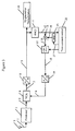
- the digital gain control signal 18 at the output of the low-pass filter 17 is forwarded to a digital-analogue converter 19, which transforms the digital gain control signal 18 into the analogue gain control signal 6 that is used for controlling the VCA's amplification.
- the reception of a signal may be disturbed by a phenomenon called fading. Due to signal reflections and signal distortions caused by the signal's multipath propagation, the signal strength varies heavily on a small time scale. A channel that is subject to fading will further on be referred to as a "bad fading channel". According to the invention, the mean input amplitude of the analogue-digital converter is decreased in case a bad fading channel is detected.
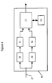
- Fig. 4 it is shown how the presence of a strong adjacent channel can be detected.
- the digital VCA output signal 27 which corresponds to the output signal 9 of the analogue-digital converter 8 in Figs. 1 to Fig. 3, is forwarded to the digital signal processing unit 28.
- a narrow bandwidth filtering 29 for the selected channel is performed, and a filtering 30 for the adjacent channels is performed as well.
- a first determination 31 of the selected channel signal strength is performed.
- a second determination 32 of the adjacent channel signal strength is performed, which is based on the output signal of filtering 30.
- Means 33 for detecting strong adjacent channels determine the ratio of the signal strength of the adjacent channel to the signal strength of the selected channel. In case said ratio exceeds a predefined threshold, then a strong adjacent channel is found.
- the reference value for the mean input signal should be augmented. For this purpose, a table 34 of reference values is accessed and a new reference value 35 is written to the corresponding register.
Landscapes
- Engineering & Computer Science (AREA)
- Computer Networks & Wireless Communication (AREA)
- Signal Processing (AREA)
- Theoretical Computer Science (AREA)
- Circuits Of Receivers In General (AREA)
- Control Of Amplification And Gain Control (AREA)
Abstract
Description
- Fig. 1
- shows a block diagram of the receiver according to the invention, whereby the analogue-digital converter's input signal is continuously monitored;
- Fig. 2
- gives another block diagram of the inventive solution, in which any saturation of the analogue-digital converter is registered;
- Fig. 3
- shows an example for an automatic gain control with a variable time constant, whereby any variations of said time constant are used for adjusting the gain control's reference level;
- Fig. 4
- shows several modules within the signal processing unit for detecting the signal strengths of the selected channel and of adjacent channels.
Claims (27)
- Amplification and digitisation unit for a receiver, preferably for a radio receiver, comprisingcharacterized byan amplifier (4) for amplifying a received signal (5) in order to obtain an amplified received signal (7),an automatic gain control unit, which controls the amplifier's gain,an analogue-digital converter (8) for converting the amplified received signal (7) into a digital signal (9) for further processing of said received signal (5),means for monitoring (20, 23, 33) the reception conditions, which track the signal strengths of adjacent channels in order to detect the presence of strong adjacent channels as said reception conditions,means for varying the mean signal amplitude of the analogue-digital converter's input signal (7) as a function of said reception conditions.
- Amplification and digitisation unit according to claim 1, characterized in that said means for monitoring the reception conditions detect instabilities/variations of the received signal's amplitude in order to determine whether the received channel is a fading channel.
- Amplification and digitisation unit according to claim 1 or claim 2, characterized in that said means for monitoring the reception conditions determine repeatedly how often the amplitude of the analogue-digital converter's input signal exceeds a predetermined threshold.
- Amplification and digitisation unit according to anyone of claims 1 to 3, characterized in that said means for monitoring the reception conditions determine how often saturation of the analogue-digital converter occurs.
- Amplification and digitisation unit according to claim 4, characterized in that said means for monitoring the reception conditions comprise a counter for counting how often saturation of the analogue-digital converter occurs.
- Amplification and digitisation unit according to anyone of the preceding claims, characterized in that said means for monitoring the reception conditions comprises a channel estimator.
- Amplification and digitisation unit according to anyone of the preceding claims, characterized in that said means for monitoring the reception conditions determine how often said automatic gain control has to readjust the amplifier's gain.
- Amplification and digitisation unit according to anyone of the preceding claims, characterized in that in case the receiver channel is a fading channel, said means for varying the mean signal amplitude decrease said mean signal amplitude of the analogue-digital converter's input signal.
- Amplification and digitisation unit according to claim 8, characterized in that said mean signal amplitude is decreased by lowering the reference value of the automatic gain control.
- Amplification and digitisation unit according to anyone of the preceding claims, characterized in that said amplification and digitisation unit comprises digital filter means for filtering the amplified digital signal.
- Amplification and digitisation unit according to anyone of the preceding claims, characterized in that said means for monitoring the reception conditions evaluate a ratio of the signal strength of an adjacent channel to the signal strength of the selected channel.
- Amplification and digitisation unit according to anyone of the preceding claims, characterized in that in case a strong adjacent channel is detected, said means for varying the mean signal amplitude increase said mean signal amplitude of the analogue-digital converter's input signal.
- Amplification and digitisation unit according to claim 12, characterized in that said mean signal amplitude is increased by augmenting the reference value of the automatic gain control unit.
- Receiver, comprising an amplification and digitisation unit according to anyone of claims 1 to 13.
- Receiver according to claim 14, characterized in that it receives AM, FM, DAB, or DRM radio signals.
- Method for amplifying and digitising a received signal, preferably a received radio signal, whereby the received signal (5) is amplified in order to obtain an amplified received signal (7), with the gain of the amplification being controlled by an automatic gain control unit, and whereby the amplified received signal (7) is converted to a digital signal (9) by an analogue-digital converter (8), characterized by the following steps:monitoring the reception conditions and tracking the signal strengths of adjacent channels in order to detect the presence of strong adjacent channels as said reception conditions;varying the mean signal amplitude of the analogue-digital converter's input signal (7) as a function of said reception conditions.
- Method according to claim 16, characterized by a step of detecting instabilities/variations of the received signal's amplitude in order to determine whether the received channel is a fading channel.
- Method according to claim 16 or 17, characterized by a step of determining repeatedly how often the amplitude of the analogue-digital converter's input signal exceeds a predetermined threshold.
- Method according to anyone of the claims 16 to 18, characterized by a step of determining how often saturation of the analogue-digital converter occurs.
- Method according to anyone of the claims 16 to 19, characterized in that said step of monitoring the reception conditions comprises a step of channel estimation.
- Method according to anyone of the claims 16 to 20, characterized by a step of determining how often said automatic gain control has to readjust the amplifier's gain.
- Method according to anyone of the claims 16 to 21, characterized by a step of decreasing said mean signal amplitude of the analogue-digital converter's input signal in case the receiver channel is a fading channel.
- Method according to claim 22, characterized by a step of lowering the reference value of the automatic gain control.
- Method according to anyone of claims 16 to 23, characterized by a step of evaluating a ratio of the signal strength of an adjacent channel to the signal strength of the selected channel.
- Method according to anyone of claims 16 to 24, characterized by a step of increasing said mean signal amplitude of the analogue-digital converter's input signal in case a strong adjacent channel is detected.
- Method according to claim 25, characterized by a step of augmenting the reference value of the automatic gain control unit.
- Computer program product, comprising computer program means adapted to perform the method steps as defined in anyone of claims 16 to 26.
Priority Applications (2)
| Application Number | Priority Date | Filing Date | Title |
|---|---|---|---|
| DE2002605590 DE60205590T2 (en) | 2002-05-16 | 2002-05-16 | Receiving device with automatic gain control |
| EP20020010952 EP1363403B8 (en) | 2002-05-16 | 2002-05-16 | Receiver with an automatic gain control |
Applications Claiming Priority (1)
| Application Number | Priority Date | Filing Date | Title |
|---|---|---|---|
| EP20020010952 EP1363403B8 (en) | 2002-05-16 | 2002-05-16 | Receiver with an automatic gain control |
Publications (3)
| Publication Number | Publication Date |
|---|---|
| EP1363403A1 true EP1363403A1 (en) | 2003-11-19 |
| EP1363403B1 EP1363403B1 (en) | 2005-08-17 |
| EP1363403B8 EP1363403B8 (en) | 2005-10-19 |
Family
ID=29265942
Family Applications (1)
| Application Number | Title | Priority Date | Filing Date |
|---|---|---|---|
| EP20020010952 Expired - Lifetime EP1363403B8 (en) | 2002-05-16 | 2002-05-16 | Receiver with an automatic gain control |
Country Status (2)
| Country | Link |
|---|---|
| EP (1) | EP1363403B8 (en) |
| DE (1) | DE60205590T2 (en) |
Cited By (4)
| Publication number | Priority date | Publication date | Assignee | Title |
|---|---|---|---|---|
| EP1848112A1 (en) * | 2006-04-21 | 2007-10-24 | Sony Corporation | Automatic gain control circuit with adjustment of target value |
| US7979049B2 (en) | 2008-03-28 | 2011-07-12 | Telefonaktiebolaget Lm Ericsson (Publ) | Automatic filter control |
| US8731500B2 (en) | 2009-01-29 | 2014-05-20 | Telefonaktiebolaget Lm Ericsson (Publ) | Automatic gain control based on bandwidth and delay spread |
| EP2347516A4 (en) * | 2008-10-17 | 2014-06-11 | Samsung Electronics Co Ltd | APPARATUS AND METHOD FOR AUTOMATIC GAIN CONTROL IN A PORTABLE COMMUNICATION SYSTEM |
Families Citing this family (1)
| Publication number | Priority date | Publication date | Assignee | Title |
|---|---|---|---|---|
| US8817923B2 (en) | 2010-06-02 | 2014-08-26 | Mitsubishi Electric Corporation | Digital broadcast receiver |
Citations (4)
| Publication number | Priority date | Publication date | Assignee | Title |
|---|---|---|---|---|
| JPH11195941A (en) * | 1997-12-26 | 1999-07-21 | Hitachi Denshi Ltd | AGC circuit |
| JPH11289499A (en) * | 1998-04-03 | 1999-10-19 | Matsushita Electric Ind Co Ltd | Television receiver |
| US6160443A (en) * | 1999-09-08 | 2000-12-12 | Atmel Corporation | Dual automatic gain control in a QAM demodulator |
| EP1061653A2 (en) * | 1999-06-18 | 2000-12-20 | Nortel Networks Limited | Analog gain control adjustment using a probabilistic algorithm |
-
2002
- 2002-05-16 EP EP20020010952 patent/EP1363403B8/en not_active Expired - Lifetime
- 2002-05-16 DE DE2002605590 patent/DE60205590T2/en not_active Expired - Lifetime
Patent Citations (4)
| Publication number | Priority date | Publication date | Assignee | Title |
|---|---|---|---|---|
| JPH11195941A (en) * | 1997-12-26 | 1999-07-21 | Hitachi Denshi Ltd | AGC circuit |
| JPH11289499A (en) * | 1998-04-03 | 1999-10-19 | Matsushita Electric Ind Co Ltd | Television receiver |
| EP1061653A2 (en) * | 1999-06-18 | 2000-12-20 | Nortel Networks Limited | Analog gain control adjustment using a probabilistic algorithm |
| US6160443A (en) * | 1999-09-08 | 2000-12-12 | Atmel Corporation | Dual automatic gain control in a QAM demodulator |
Non-Patent Citations (2)
| Title |
|---|
| PATENT ABSTRACTS OF JAPAN vol. 1999, no. 12 29 October 1999 (1999-10-29) * |
| PATENT ABSTRACTS OF JAPAN vol. 2000, no. 01 31 January 2000 (2000-01-31) * |
Cited By (6)
| Publication number | Priority date | Publication date | Assignee | Title |
|---|---|---|---|---|
| EP1848112A1 (en) * | 2006-04-21 | 2007-10-24 | Sony Corporation | Automatic gain control circuit with adjustment of target value |
| US8045659B2 (en) | 2006-04-21 | 2011-10-25 | Sony Corporation | OFDM receiver and its automatic gain control circuit |
| US7979049B2 (en) | 2008-03-28 | 2011-07-12 | Telefonaktiebolaget Lm Ericsson (Publ) | Automatic filter control |
| EP2347516A4 (en) * | 2008-10-17 | 2014-06-11 | Samsung Electronics Co Ltd | APPARATUS AND METHOD FOR AUTOMATIC GAIN CONTROL IN A PORTABLE COMMUNICATION SYSTEM |
| US8811549B2 (en) | 2008-10-17 | 2014-08-19 | Samsung Electronics Co., Ltd. | Apparatus and method for automatically controlling gain in portable communication system |
| US8731500B2 (en) | 2009-01-29 | 2014-05-20 | Telefonaktiebolaget Lm Ericsson (Publ) | Automatic gain control based on bandwidth and delay spread |
Also Published As
| Publication number | Publication date |
|---|---|
| DE60205590D1 (en) | 2005-09-22 |
| DE60205590T2 (en) | 2006-06-08 |
| EP1363403B1 (en) | 2005-08-17 |
| EP1363403B8 (en) | 2005-10-19 |
Similar Documents
| Publication | Publication Date | Title |
|---|---|---|
| EP0812064B1 (en) | Reception automatic gain control system and method | |
| US9001941B2 (en) | Method and apparatus to independently control front end gain and baseband gain | |
| US5563916A (en) | Apparatus and method for varying the slew rate of a digital automatic gain control circuit | |
| US6993291B2 (en) | Method and apparatus for continuously controlling the dynamic range from an analog-to-digital converter | |
| US5946607A (en) | Method of apparatus for automatic gain control, and digital receiver using same | |
| JP5554769B2 (en) | Automatic filter control | |
| US8442154B2 (en) | Channel sensitive power control | |
| EP1309093A2 (en) | Method and apparatus for reducing the effect of AGC switching transients | |
| US7072632B2 (en) | Fast signal detection process | |
| US7570934B2 (en) | Automatic gain control circuit | |
| US20130324065A1 (en) | Method and Apparatus for Auto Gain Control in Radio Receiver | |
| EP1434345B1 (en) | Telecommunications receiver with automatic gain control | |
| US5450035A (en) | Automatic gain control apparatus | |
| EP1129522A1 (en) | Method and apparatus for automatic gain control | |
| EP1515428B1 (en) | Automatic gain control method for radio communication mobile station | |
| US20040087287A1 (en) | Automatic gain control system | |
| EP1363403B1 (en) | Receiver with an automatic gain control | |
| US7680473B2 (en) | Circuits and methods for signal gain control | |
| US7327807B2 (en) | Method for controlling generation of transmission power control information, method of controlling characteristics of receiver circuit based on overflow information, and CDMA communication apparatus | |
| JP5407596B2 (en) | Wireless communication apparatus and signal strength measuring method | |
| EP2104226B1 (en) | Wireless communication device | |
| JP2004134917A (en) | Automatic gain control device, wireless receiving device, and automatic gain control method | |
| KR100690438B1 (en) | Automatic gain control method with variable gain adjustment interval and device | |
| US7447283B2 (en) | Method for automatic gain control, for instance in a telecommunication system, device and computer program product therefor | |
| JP2003318679A (en) | Receiving device and communication device |
Legal Events
| Date | Code | Title | Description |
|---|---|---|---|
| PUAI | Public reference made under article 153(3) epc to a published international application that has entered the european phase |
Free format text: ORIGINAL CODE: 0009012 |
|
| AK | Designated contracting states |
Kind code of ref document: A1 Designated state(s): AT BE CH CY DE DK ES FI FR GB GR IE IT LI LU MC NL PT SE TR |
|
| AX | Request for extension of the european patent |
Extension state: AL LT LV MK RO SI |
|
| 17P | Request for examination filed |
Effective date: 20031010 |
|
| 17Q | First examination report despatched |
Effective date: 20031205 |
|
| AKX | Designation fees paid |
Designated state(s): DE FR GB |
|
| GRAP | Despatch of communication of intention to grant a patent |
Free format text: ORIGINAL CODE: EPIDOSNIGR1 |
|
| GRAS | Grant fee paid |
Free format text: ORIGINAL CODE: EPIDOSNIGR3 |
|
| GRAA | (expected) grant |
Free format text: ORIGINAL CODE: 0009210 |
|
| AK | Designated contracting states |
Kind code of ref document: B1 Designated state(s): DE FR GB |
|
| REG | Reference to a national code |
Ref country code: GB Ref legal event code: FG4D |
|
| REF | Corresponds to: |
Ref document number: 60205590 Country of ref document: DE Date of ref document: 20050922 Kind code of ref document: P |
|
| RAP2 | Party data changed (patent owner data changed or rights of a patent transferred) |
Owner name: SONY DEUTSCHLAND GMBH |
|
| ET | Fr: translation filed | ||
| PLBE | No opposition filed within time limit |
Free format text: ORIGINAL CODE: 0009261 |
|
| STAA | Information on the status of an ep patent application or granted ep patent |
Free format text: STATUS: NO OPPOSITION FILED WITHIN TIME LIMIT |
|
| 26N | No opposition filed |
Effective date: 20060518 |
|
| PGFP | Annual fee paid to national office [announced via postgrant information from national office to epo] |
Ref country code: FR Payment date: 20110607 Year of fee payment: 10 |
|
| PGFP | Annual fee paid to national office [announced via postgrant information from national office to epo] |
Ref country code: GB Payment date: 20110520 Year of fee payment: 10 |
|
| PGFP | Annual fee paid to national office [announced via postgrant information from national office to epo] |
Ref country code: DE Payment date: 20110520 Year of fee payment: 10 |
|
| GBPC | Gb: european patent ceased through non-payment of renewal fee |
Effective date: 20120516 |
|
| REG | Reference to a national code |
Ref country code: FR Ref legal event code: ST Effective date: 20130131 |
|
| REG | Reference to a national code |
Ref country code: DE Ref legal event code: R119 Ref document number: 60205590 Country of ref document: DE Effective date: 20121201 |
|
| PG25 | Lapsed in a contracting state [announced via postgrant information from national office to epo] |
Ref country code: FR Free format text: LAPSE BECAUSE OF NON-PAYMENT OF DUE FEES Effective date: 20120531 Ref country code: GB Free format text: LAPSE BECAUSE OF NON-PAYMENT OF DUE FEES Effective date: 20120516 |
|
| PG25 | Lapsed in a contracting state [announced via postgrant information from national office to epo] |
Ref country code: DE Free format text: LAPSE BECAUSE OF NON-PAYMENT OF DUE FEES Effective date: 20121201 |