EP1363373A2 - A device for drawing and replacing cables and a method of drawing and replacing cables by means of the device - Google Patents
A device for drawing and replacing cables and a method of drawing and replacing cables by means of the device Download PDFInfo
- Publication number
- EP1363373A2 EP1363373A2 EP03388036A EP03388036A EP1363373A2 EP 1363373 A2 EP1363373 A2 EP 1363373A2 EP 03388036 A EP03388036 A EP 03388036A EP 03388036 A EP03388036 A EP 03388036A EP 1363373 A2 EP1363373 A2 EP 1363373A2
- Authority
- EP
- European Patent Office
- Prior art keywords
- cable
- slot
- hollow body
- replacement
- cables
- Prior art date
- Legal status (The legal status is an assumption and is not a legal conclusion. Google has not performed a legal analysis and makes no representation as to the accuracy of the status listed.)
- Withdrawn
Links
Images


Classifications
-
- H—ELECTRICITY
- H02—GENERATION; CONVERSION OR DISTRIBUTION OF ELECTRIC POWER
- H02G—INSTALLATION OF ELECTRIC CABLES OR LINES, OR OF COMBINED OPTICAL AND ELECTRIC CABLES OR LINES
- H02G1/00—Methods or apparatus specially adapted for installing, maintaining, repairing or dismantling electric cables or lines
- H02G1/06—Methods or apparatus specially adapted for installing, maintaining, repairing or dismantling electric cables or lines for laying cables, e.g. laying apparatus on vehicle
- H02G1/08—Methods or apparatus specially adapted for installing, maintaining, repairing or dismantling electric cables or lines for laying cables, e.g. laying apparatus on vehicle through tubing or conduit, e.g. rod or draw wire for pushing or pulling
- H02G1/085—Methods or apparatus specially adapted for installing, maintaining, repairing or dismantling electric cables or lines for laying cables, e.g. laying apparatus on vehicle through tubing or conduit, e.g. rod or draw wire for pushing or pulling using portable tools
Definitions
- the invention relates to a device for drawing and replacing cables, preferably communication and power cables or supply lines, through narrow, long passageways, said device being shaped as a substantially cylindrical hollow body tapering as a truncated cone below a certain angle.
- the invention further relates to a method of drawing and replacing cables or lines by means of the device.
- WO 97/42531 A1 discloses a system for the drawing of cables.
- the system includes two bodies, particularly a protective coat for mounting on a cable with a connector and further a pulling body, which is tapered in the pulling direction.
- the coat is also egg-shaped and tapers in the direction opposite the pulling direction.
- the coat is relatively expensive to produce, as an assembly mechanism for the coat comprises a threaded cover in the pulling direction.
- WO 98/20602 discloses a cable forerunner for winding high-voltage cables in an electric motor, wherein one end of the cable forerunner is attached to the end of the cable, the cable forerunner being arranged to draw the cable through a first slot in the motor stator and to control the curvature of the cable from its exit from the slot to its entry into a second slot in the motor stator.
- the disclosed cable forerunner is adapted for the re-winding of high-voltage cables, which typically have a diameter between 20 and 350 mm, in the stator slots of a motor.
- EP 427 354 B2 discloses an apparatus for introducing (installing) cables, such as for instance optical glass fibre cables, into a channelization system of guide tubes, commonly denoted as ducts, which are usually placed in the ground.
- ducts a channelization system of guide tubes, commonly denoted as ducts, which are usually placed in the ground.
- ducts pneumatic, pneumatic motors, etc. are used to this end.
- the apparatus disclosed can only be used for applications, wherein guide tubes are already provided and not for instance for replacing a cable in a cable bundle.
- the present invention is based on the realization that the replacement of a cable may be facilitated, if the cable to be replaced is able to draw the replacement cable, a line or a draw string, along through its former position. It is the object of the present invention to provide a device, which is able to reduce the risk of a cable or its connector being stuck in a transverse structure.
- the device in its lateral wall is provided with a slot being parallel to the axis and extending in the entire length of the hollow body, the width of the hollow body being substantially less than that of the cable or line to be drawn, and that the internal diameter of the majority of the hollow body exceeds the slot and may substantially enclose a line or a connector mounted on a cable, the diameter in the outermost tapered end of the hollow body being reduced to the width of the slot.
- a cable may be extracted from a cable bunch without the connector being removed, said connector being embedded in the device during the entire extraction process.
- the cable to be replaced may furthermore be connected to the replacement cable, which further may be provided with a device according to the invention, whereby the drawing of the new cable is effected in the same movement as the extraction of the cable to be replaced.
- a pre-arranged draw string may draw a power cable or a supply line, the supply line being arranged inside the cylindrical hollow body.
- the reduction of the internal diameter of the tip of the hollow body is gradual. This feature enables the device to be retained by the connector on the cable without the connector becoming wedged in the device. As a result the extraction of the cable with the connector from the device is facilitated after completion of the pull-through.
- angle ⁇ in the open interval between 0° and 45° and more advantageous to use an angle ⁇ in the open interval between 15° and 25° and most advantageous to use an angle in the open interval between 18° and 22°.
- the angle has to be less than 45°, as the pull-through otherwise would be rendered more difficult.
- the angle must not be too small, as this extends the device, which in turn renders the passage of the device through narrow curves of cable bunches more difficult.
- the transition between the truncated cone and the cylindrical hollow body may be rounded, eg as a bottle shoulder.
- the device may be made from a material with a low specific coefficient of friction.
- a material from the group of chemical compounds represented by for instance polytetrafluoroethylene PTFE or similar plastics having a low specific coefficient of friction such as for instance polyoxy methylene, POM.
- a method of replacing cables by means of the device according to the invention a cable to be replaced being connected for drawing to a replacement cable using suitable means, the replacement cable being inserted into a first device through the slot therein, the first device then being drawn along the cable to the end of the cable while enclosing the connector, the replacement cable being inserted into a second device through the slot, the device then being drawn along the replacement cable to the end of the cable while enclosing the connector, whereafter the cable to be replaced may be pulled through along with replacement cable.
- the second device is retained by means of the locking arm of the connector, said locking arm being forced against the inner face of the second device by means of the draw connection's draw.
- the suggested method may also be used for the replacement of a draw string or merely for the removal of the cable, the device being used only for the removal of the specific cable.
- a method may also be carried out by means of the device according to the invention, when an existing draw string is to draw a supply line through narrow passages.
- the draw string in the line which may be a high-voltage cable or a hydraulic or water line, is secured by means of a single guide in the high-voltage cable or secured in a bore, which may extend transversely of the line aperture.
- the joining means between the cable to be replaced and the replacement cable is formed of closed loop, preferably an O-ring or a 1 ⁇ 2" gasket. It is, however, obvious that any closed loop of a suitable size may be used as draw connection between the two cables, the distance between the cable terminals, however, not being too great, as the replacement cable otherwise would present to much resistance and possibly become stuck in transverse structures or narrow curves.
- Figure 1 shows the device 1 with the cylindrical hollow body 2, which in the draw direction tapers into a truncated cone 5 below an angle ( ⁇ ) and in its lateral wall is provided with a slot 3 being parallel to the axis and extending in the entire length of the hollow body 1, the width b of the hollow body corresponding to that of a cable to be drawn.
- the figure thus shows the internal diameter d of the cylindrical portion 2 of the hollow body 1, said diameter exceeding the slot 3 and being able to substantially enclose a connector mounted on the cable.
- the diameter is reduced to the width b of the slot 3.
- the figure thus shows a gradual reduction of the diameter d.
- Figure 2 shows the device 1 with the cable arranged in the slot 3.
- the connector is an AMP RJ45 used in a telecommunications network.
- the connector may also be an optical fibre connector of the type VF45 made by 3M.
- This connector is characterised by being provided with a small locking arm, which secures the connector in the associated port and like a barb projects from the connector body per se.
- Figure 3 shows the completely mounted device, the locking arm on the connector, however, being arranged in the slot 3. In order to eliminate the locking arm completely the connector may rotate about its longitudinal axis such that the locking arm is provided under the device's 1 encasing in the cylindrical portion 2 of the hollow body 1.
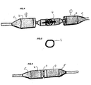
- Figure 4 shows a joining of two cables, the device 1, however, not being pushed into its final position over the connectors, which also in this example are AMP RJ45 connectors.
- a loop is shown, in this example the loop is secured to the locking arms of the two connectors, said procedure being completely secure, as the locking arm are prevented from swinging to the side and thus break, when the device 1 has been correctly arranged.
- Figure 5 shows an example of a loop 4 which may be made from any suitable material. However, it is considered advantageous to use an O-ring, which is available in several sizes or a 1 ⁇ 2" gasket, which are often very easy to provide.
- Figure 6 shows a completed joining of the two cables, the device 1 being pushed into position over the connectors. As evident, due to the small gap between the connector ends, the assembly is flexible and may easily be passed through comparatively narrow curves.
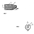
- Figure 7 shows another embodiment of the slot 3, in which the width b of the slot 3 moderately increases opposite the draw direction.
- the angle ⁇ defined by the angle of the truncated cone from the cone axis is furthermore illustrated.
- Figure 8 shows an example of a cross section through the device 1. It is shown that the internal diameter exceeds the width b of the slot 3.
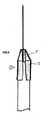
- Figure 9 shows the device according to the invention used on a high-voltage cable or a supply line, which may be a so-called PEX tube for water or hydraulic installations.
- the cable or line is of a calibre, which completely fills the interior of the cylindrical portion 2 of the hollow body 1, wherein a draw string is secured to the cable or line.
- Such cables or lines are not provided with connectors, for which reason said cables or lines may be effortlessly extracted from a cable or lines bunch, optionally along with a new draw string. A fast and uncomplicated replacement of cables or lines is thus obtained.
- the device according to the invention offers a fast and thus cost-effective replacement of cables and lines of any type forming part of a cable or line bunch.
Landscapes
- Processing Of Terminals (AREA)
- Light Guides In General And Applications Therefor (AREA)
Abstract
Description
- Figure 1
- is a perspective view of the device according to the invention when seen from the frustum end of the hollow body,
- Figure 2
- is a perspective view of the device according to the invention, the cable being provided in the slot,
- Figure 3
- is a perspective view of the device according to the invention, in which the connector has been inserted into the hollow body,
- Figure 4
- is a view of two devices according to the invention during preparation of the method according to the invention,
- Figure 5
- illustrates an example of a closed loop, which can be used as a joining means,
- Figure 6
- is a view of two devices according to the method enclosing the connectors,
- Figure 7
- is a view of a device according to the invention, the slot being visible and the angle being indicated,
- Figure 8
- illustrates an example of a cross section of the device according to the invention, and
- Figure 9
- illustrates an embodiment in which the device is used on a high-voltage cable or a supply line with a draw string.
Claims (10)
- Device for drawing and replacing cables, preferably communication and supply cables, the device being shaped as a substantially cylindrical hollow body (2), which in the draw direction tapers as a truncated cone (5) below an angle (α), characterised in that in its lateral wall the device is provided with a slot (3) being parallel to the axis and extending in the entire length of the hollow body (1) and having a width (b) corresponding substantially to that of a cable to be drawn and that the internal diameter (d) of the majority of the hollow body (1) exceeds the slot (3) and may substantially enclose a connector mounted on a cable, the diameter (d) in the outermost tapered end of the hollow body being reduced to the width of the slot.
- Device according to claim 1, characterised in that the diameter (d) is gradually reduced.
- Device according to claim 1 or 2, characterised in that the angle (α) is in the open interval between 0° and 45°.
- Device according to any of the preceding claims, characterised in that the angle (α) is in the open interval between 15° and 25°.
- Device according to any of the preceding claims, characterised in that the angle (α) is in the open interval between 18° and 22°.
- Device according to any of the preceding claims, characterised in that the transition between the truncated cone (5) and the cylindrical hollow body is rounded.
- Device according to any of the preceding claims, characterised in that it is made from a material with a low specific coefficient of friction.
- Device according to claim 7, characterised in that the material is found among the group of chemical compounds represented by for instance polytetrafluoroethylene PTFE or similar plastics having a low specific coefficient of friction, as such for instance polyoxy methylene, POM.
- Method for the replacement of cables by means of the device according to any of the preceding claim, characterised in that(1) a cable to be replaced is connected for drawing to a replacement cable using suitable means (4),(2) the replacement cable is inserted into a first device (1) through the slot (3) thereof,(a) the first device (1) is then drawn along the cable to be replaced to the end of the cable while enclosing the connector,(3) the replacement cable is inserted into a second device (1) through the slot (3) thereof,(a) this device (1) is then drawn along the replacement cable to the end of the cable while enclosing the connector,(4) whereafter the cable to be replaced is pulled through along with the replacement cable.
- Method according to claim 9, characterised in that the joining means (4) between the cable to be replaced and the replacement cable is formed of a closed loop (4).
Applications Claiming Priority (2)
| Application Number | Priority Date | Filing Date | Title |
|---|---|---|---|
| DK200200745A DK174951B1 (en) | 2002-05-14 | 2002-05-14 | Device for pulling and replacing cables and method for pulling and replacing cables using the device |
| DK200200745 | 2002-05-14 |
Publications (2)
| Publication Number | Publication Date |
|---|---|
| EP1363373A2 true EP1363373A2 (en) | 2003-11-19 |
| EP1363373A3 EP1363373A3 (en) | 2004-12-15 |
Family
ID=29265862
Family Applications (1)
| Application Number | Title | Priority Date | Filing Date |
|---|---|---|---|
| EP03388036A Withdrawn EP1363373A3 (en) | 2002-05-14 | 2003-05-14 | A device for drawing and replacing cables and a method of drawing and replacing cables by means of the device |
Country Status (2)
| Country | Link |
|---|---|
| EP (1) | EP1363373A3 (en) |
| DK (1) | DK174951B1 (en) |
Cited By (2)
| Publication number | Priority date | Publication date | Assignee | Title |
|---|---|---|---|---|
| CN114421365A (en) * | 2021-12-30 | 2022-04-29 | 中国航天空气动力技术研究院 | Auxiliary threading device |
| WO2023141709A1 (en) * | 2022-01-26 | 2023-08-03 | 13447685 Canada Inc. | Devices and methods for pulling terminated and unterminated cables |
Family Cites Families (2)
| Publication number | Priority date | Publication date | Assignee | Title |
|---|---|---|---|---|
| AU2577197A (en) * | 1996-05-02 | 1997-11-26 | Takayasu Kanemura | Protector used for pulling end of cable connector |
| FR2804762B1 (en) * | 2000-02-08 | 2002-04-12 | France Telecom | FIXING SLEEVE FOR OPTICAL CABLES |
-
2002
- 2002-05-14 DK DK200200745A patent/DK174951B1/en not_active IP Right Cessation
-
2003
- 2003-05-14 EP EP03388036A patent/EP1363373A3/en not_active Withdrawn
Cited By (3)
| Publication number | Priority date | Publication date | Assignee | Title |
|---|---|---|---|---|
| CN114421365A (en) * | 2021-12-30 | 2022-04-29 | 中国航天空气动力技术研究院 | Auxiliary threading device |
| CN114421365B (en) * | 2021-12-30 | 2023-12-12 | 中国航天空气动力技术研究院 | An auxiliary threading device |
| WO2023141709A1 (en) * | 2022-01-26 | 2023-08-03 | 13447685 Canada Inc. | Devices and methods for pulling terminated and unterminated cables |
Also Published As
| Publication number | Publication date |
|---|---|
| EP1363373A3 (en) | 2004-12-15 |
| DK174951B1 (en) | 2004-03-22 |
| DK200200745A (en) | 2003-11-15 |
Similar Documents
| Publication | Publication Date | Title |
|---|---|---|
| US6554489B2 (en) | Fiber optic cable guide and method of application | |
| CA2467513C (en) | Optical fibre drop cables | |
| EP1855134A2 (en) | A cable assembly as well as a method for installing such a cable assembly | |
| US20050069275A1 (en) | Optical fibre tube sealing | |
| KR100227976B1 (en) | Spiral hanger for cable and method of installing a cable using the same | |
| CN100550548C (en) | Systems and devices for pulling optical fibers along ducts | |
| AU664376B2 (en) | Empty conduit with detachable cable assembly and method of making same | |
| EP0813271A3 (en) | Wire end alignment assembly for wire crimping apparatus | |
| CN211209184U (en) | Cable protection sleeve | |
| HU221711B1 (en) | Tool and method for sheathing of cables | |
| EP0862254A3 (en) | Cable sealing | |
| JPH11178182A (en) | Spiral support for cable suspension and its construction method | |
| DK174951B1 (en) | Device for pulling and replacing cables and method for pulling and replacing cables using the device | |
| CN212571922U (en) | Cable pulling structure | |
| US4805878A (en) | Anti-rotation cable stringing | |
| DK200200148U3 (en) | Device for pulling and replacing cables and using the device for the same | |
| US6401570B1 (en) | Cable stripping tool | |
| KR20040093135A (en) | Cable installation | |
| US5639068A (en) | Cable lead tool | |
| CN211605923U (en) | Embrace folder and cable and carry structure of drawing | |
| JP2000152449A (en) | Spiral support for cable suspension and method of construction | |
| US20040103501A1 (en) | Apparatus and method for clamping cable | |
| CN203895882U (en) | Opening line pipe | |
| CN211606045U (en) | Cable holding and clamping structure | |
| JP2006034080A (en) | Coil stretcher for cable installation |
Legal Events
| Date | Code | Title | Description |
|---|---|---|---|
| PUAI | Public reference made under article 153(3) epc to a published international application that has entered the european phase |
Free format text: ORIGINAL CODE: 0009012 |
|
| AK | Designated contracting states |
Kind code of ref document: A2 Designated state(s): AT BE BG CH CY CZ DE DK EE ES FI FR GB GR HU IE IT LI LU MC NL PT RO SE SI SK TR |
|
| AX | Request for extension of the european patent |
Extension state: AL LT LV MK |
|
| 17P | Request for examination filed |
Effective date: 20040503 |
|
| PUAL | Search report despatched |
Free format text: ORIGINAL CODE: 0009013 |
|
| AK | Designated contracting states |
Kind code of ref document: A3 Designated state(s): AT BE BG CH CY CZ DE DK EE ES FI FR GB GR HU IE IT LI LU MC NL PT RO SE SI SK TR |
|
| AX | Request for extension of the european patent |
Extension state: AL LT LV MK |
|
| RIC1 | Information provided on ipc code assigned before grant |
Ipc: 7G 02B 6/44 B Ipc: 7H 02G 1/08 A |
|
| AKX | Designation fees paid |
Designated state(s): AT BE BG CH CY CZ DE DK EE ES FI FR GB GR HU IE IT LI LU MC NL PT RO SE SI SK TR |
|
| AXX | Extension fees paid |
Extension state: MK Payment date: 20030520 Extension state: LV Payment date: 20030520 Extension state: LT Payment date: 20030520 Extension state: AL Payment date: 20030520 |
|
| 17Q | First examination report despatched |
Effective date: 20060804 |
|
| GRAP | Despatch of communication of intention to grant a patent |
Free format text: ORIGINAL CODE: EPIDOSNIGR1 |
|
| STAA | Information on the status of an ep patent application or granted ep patent |
Free format text: STATUS: THE APPLICATION IS DEEMED TO BE WITHDRAWN |
|
| 18D | Application deemed to be withdrawn |
Effective date: 20080529 |