EP1363304A1 - Commutateur à ouverture de type à fils exploses et procédé de fabrication - Google Patents
Commutateur à ouverture de type à fils exploses et procédé de fabrication Download PDFInfo
- Publication number
- EP1363304A1 EP1363304A1 EP03101393A EP03101393A EP1363304A1 EP 1363304 A1 EP1363304 A1 EP 1363304A1 EP 03101393 A EP03101393 A EP 03101393A EP 03101393 A EP03101393 A EP 03101393A EP 1363304 A1 EP1363304 A1 EP 1363304A1
- Authority
- EP
- European Patent Office
- Prior art keywords
- conductive lines
- switch according
- turns
- insulating support
- switch
- Prior art date
- Legal status (The legal status is an assumption and is not a legal conclusion. Google has not performed a legal analysis and makes no representation as to the accuracy of the status listed.)
- Granted
Links
- 238000004519 manufacturing process Methods 0.000 title claims description 6
- 239000002360 explosive Substances 0.000 title description 2
- 238000000034 method Methods 0.000 title description 2
- 239000004020 conductor Substances 0.000 claims abstract description 19
- 239000012212 insulator Substances 0.000 claims description 14
- 238000005530 etching Methods 0.000 claims description 3
- 208000031968 Cadaver Diseases 0.000 description 4
- 230000015556 catabolic process Effects 0.000 description 4
- 230000005684 electric field Effects 0.000 description 3
- 239000010410 layer Substances 0.000 description 3
- 239000007787 solid Substances 0.000 description 3
- 229920000297 Rayon Polymers 0.000 description 2
- 230000003247 decreasing effect Effects 0.000 description 2
- 230000000694 effects Effects 0.000 description 2
- 239000002964 rayon Substances 0.000 description 2
- 235000005282 vitamin D3 Nutrition 0.000 description 2
- 239000011647 vitamin D3 Substances 0.000 description 2
- RYGMFSIKBFXOCR-UHFFFAOYSA-N Copper Chemical compound [Cu] RYGMFSIKBFXOCR-UHFFFAOYSA-N 0.000 description 1
- 239000004642 Polyimide Substances 0.000 description 1
- 229910052802 copper Inorganic materials 0.000 description 1
- 239000010949 copper Substances 0.000 description 1
- 239000003989 dielectric material Substances 0.000 description 1
- 239000000155 melt Substances 0.000 description 1
- 239000002184 metal Substances 0.000 description 1
- 229910052751 metal Inorganic materials 0.000 description 1
- 239000004033 plastic Substances 0.000 description 1
- 229920003223 poly(pyromellitimide-1,4-diphenyl ether) Polymers 0.000 description 1
- 229920001721 polyimide Polymers 0.000 description 1
- 230000000630 rising effect Effects 0.000 description 1
- 239000002356 single layer Substances 0.000 description 1
Images


Classifications
-
- H—ELECTRICITY
- H01—ELECTRIC ELEMENTS
- H01H—ELECTRIC SWITCHES; RELAYS; SELECTORS; EMERGENCY PROTECTIVE DEVICES
- H01H33/00—High-tension or heavy-current switches with arc-extinguishing or arc-preventing means
- H01H33/002—Very heavy-current switches
-
- H—ELECTRICITY
- H01—ELECTRIC ELEMENTS
- H01H—ELECTRIC SWITCHES; RELAYS; SELECTORS; EMERGENCY PROTECTIVE DEVICES
- H01H39/00—Switching devices actuated by an explosion produced within the device and initiated by an electric current
- H01H39/006—Opening by severing a conductor
Definitions
- the present invention relates to a switch with opening of type with exploded wires and a manufacturing process. It applies in particular switches used in high pulsed power systems.
- Such a switch is typically used in a circuit electric comprising a high impedance load and a power supply low impedance.
- the switch is initially conductive. In others terms, its resistance before switching is almost zero.
- the switch short-circuits the load.
- the power supplies a current crescent flowing through the switch.
- the switch opens. In other words, when switching its resistance tends to infinity. At this moment all the current flows in the charge.
- the switch thus makes it possible to format a pulse of current. More precisely, it makes it possible to reduce the duration of the rising edge and increase the voltage across its terminals.
- a switch ideally has a resistance before switching as low as possible, resistance after highest possible switching time, and the longest switching time weak possible.
- pyrotechnic switches There are several families of opening switches: pyrotechnic switches, plasma switches ("plasma opening switch "in Anglo-Saxon literature), wire switches exploded. Pyrotechnic switches use a system dihedral hollow charge type pyrotechnics to cut a driver. In plasma switches, the conductive phase is due to a plasma that is interrupted to open the switch.
- the exploded wire switches initially include metallic wires conductors in which the flow of current causes an increase in temperature that melts and then vaporizes the conductor. The resistivity of son increases considerably which ensures the function of switching.
- the present invention aims to optimize the volume occupied by the Explosive wire type opening switches, the volume allocated to these switches being a substantially cylindrical volume.
- the invention consists in distributing the active volume of the switch (conductive lines) homogeneously in the allocated volume. Through elsewhere one of the proposed solutions has advantages in terms industrialization.
- the lines conductive form axial undulations.
- the conductive lines describe turns around of the cylinder axis.
- a wire switch exploded generally includes at least one wire 4 stretched over a frame insulating plane 3. One end of this wire is intended to be connected to a ground. The other end is intended to be connected to a hot spot, i.e. to a point of high potential.
- Several wires of the same length can be mounted in parallel in planes parallel to the insulating frame. Such a switch is not optimized to occupy a substantially cylindrical volume.
- the switch has a body 6 which occupies substantially a volume delimited by a cylinder with an axis 10.
- the body includes an insulator on which conductive lines are deposited. These conductive lines can be formed by filaments of a few tens of micrometers in section for example.
- switches used in high systems pulsed power a large number of lines are preferably used conductors (of the order of a hundred) of small cross section (of the order of one ten micrometers). Indeed, the switching time is all the more weak as the section is weak. And, the amount of energy that can be the greater the sum of the sections of the conductive lines is important.
- the conductive lines are formed by tracks engraved on a support insulating. They can be engraved on an intermediate insulating support as described in connection with Figure 4 or directly on the insulator. They can be made for example by photoengraving.
- the body includes several insulators between which the lines are located conductive. Each insulator separates two layers of conductive lines. The conductive lines can be parallel between the layers successive. According to another embodiment (shown in Figures 2 and 3) the body consists of a single layer of conductive lines and two insulators 6A, 6B between which the conductive lines are located.
- the conductive lines are placed in the body 6. They extend in a radial direction with respect to the axis 10 of the cylinder towards the outer casing 6C of the body.
- the conductive lines are intended for be connected to a central conductor 1 substantially on the axis 10 of the cylinder on the one hand, and to a mass 2 at the level of the outer casing 6C of the body on the other hand.
- the invention leads to a coaxial structure at the potential with high potential on axis 10 and mass on the outside. This switch is thus suitable for a supply or a load of coaxial geometry.
- the central conductor can be a rigid connector such as a metal rod.
- the body 6 may include a recess 11 substantially on axis 10 to accommodate the central conductor 1.
- Obviously 11 may have the shape of a cylinder with an axis 10. According to a variant of realization, the body does not understand obviously but includes a point of contact on its external surface, this point of contact being substantially positioned at axis 10. The central conductor is then shaped adapted to this point of contact. So the end of the conductive lines connected to the central conductor 1 is either substantially on the axis 10 (body without obviously), or close to this axis (body with obviously).
- the conductive lines 5 form axial undulations. These ripples may for example be formed by a substantially sinusoidal curve. According to another embodiment, they can be formed by straight segments arranged in W and connected by rounds. In others terms, the conductive lines are folded in a direction parallel to axis 10. This makes it possible to generate longer conducting lines while retaining a switch which occupies a substantially delimited volume by a cylinder of the same radius. This geometry has two advantages.
- the arrangement described above allows to optimize the electric field levels in the dielectric volumes and thus minimizing the risk of breakdown.
- the body comprises at least two insulators recessed between which the conductive lines are located.
- Isolators 6A, 6B separate as illustrated in Figure 3 the successive undulations. Thanks to their corrugated forms, the insulators have the effect of limiting breakdown by rampage.
- the rampage breakdown specific to solid dielectrics, is a breakdown in which the current takes a geometric path to the surface of a solid dielectric.
- the switch can include a flexible insulating film 7 on which tracks are engraved forming the conductive lines.
- the film can be a sheet in plastic such as a polyimide sheet (known as Kapton commercial), the conductive lines being produced by a depot of copper.
- Kapton commercial a polyimide sheet
- This insulating film can thus be easily folded, which allows generate the axial undulations of the conductive lines without risking them to break up.
- This embodiment is particularly suitable for lines conductors of small cross-section.
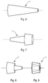
- the insulating film substantially forms a cone folded. This allows to generate ripples in W as described more high. There is also an advantageous structure in terms industrialization.
- the isolators 6A and 6B being rigid insulators, we can generate the folds of the film (and by consequent conductive lines) by embedding the insulators one in the other, the flexible film located between said insulators.
- Conductive lines 5 describe turns around of axis 10 of the cylinder.
- the conductive lines 5 can also form axial undulations as indicated above.
- the lines conductors can simply describe turns in a plane without form axial ripples. This increases the length of the lines without increasing the volume occupied by them. It is possible to adjust their length by changing the number of turns.
- Figure 11 is represented a flexible insulating support forming a cone. It is possible to combine the advantageous embodiments so as to obtain undulations axial and turns using a folded cone on which are engraved turns. We can thus reach a typical line length of 4 meters in a small footprint.
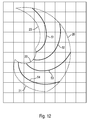
- FIG. 12 is represented between edges 20,21,22,23 shown in dotted lines a surface developed from a cone.
- the edges 21 and 23 of this surface are intended to be glued to generate a conical surface.
- the edge 20 is intended for form the base of the cone (circle), and the edge 21 the top of the cone (circle).
- the conductive lines 51, 52, 53, 54 in this example form a half turn.
- the grid in Figure 12 is a unit grid: each box has a vertical side of length 1 and a horizontal side of width 1.
- the conductive lines do not describe more turns but straight lines. This corresponds to the mode of realization shown in Figures 2 to 5.
- the number N can take any value positive (turns in the direction illustrated in Figure 12) or negative (turns in the other direction).
- the self induced by the Current flow in the conductive lines can become troublesome.
- one can compensate for this self by carrying out turns in the opposite direction with another layer of conductive lines.
- part of the conductive lines describe turns in one direction and the other part of the conductive lines describe lines in the other direction.
- the conductive lines Preferably, as many conductive lines are used to describe turns in one direction than in the other direction.
- the guidelines that describe turns in one direction can be placed on one side of an insulating support, the conductive lines describing turns in the other direction being deposited on the other side.
- This insulating support can be a flexible film or a rigid insulator or any other support.
- the conductive lines describing turns in one direction are deposited on a first support insulating, the conductive lines describing turns in the other direction are deposited on a second insulating support.
- This embodiment allows avoid having to make junctions of conductive lines while keeping the possibility of engraving the tracks flat.
- the first and the second insulating support are nested one inside the other.
Landscapes
- Push-Button Switches (AREA)
Abstract
Description
- un corps occupant sensiblement un volume délimité par un cylindre ;
- des lignes conductrices placées dans le corps, les lignes conductrices s'étendant dans une direction radiale vers l'enveloppe extérieure du corps, les lignes conductrices étant destinées à être reliées à un conducteur central sensiblement sur l'axe du cylindre d'une part, et à une masse au niveau de l'enveloppe extérieure du corps d'autre part, les lignes conductrices étant destinées à être rompues lors du passage d'un courant électrique entre le conducteur central et la masse.
- on réalise des pistes conductrices par gravure sur un film souple dont la surface est le développement d'un cône, ce film étant à plat lors de la réalisation de ces pistes ;
- on génère une forme conique à partir de cette surface ;
- on réalise des repliements du cône dans une direction axiale.
- la figure 1, une vue de dessus, représente un commutateur à ouverture de type à fils explosés classique ;
- la figure 2, une vue de dessus, représente un exemple de commutateur selon l'invention ;
- la figure 3, une section, représente le commutateur de la figure 2 ;
- la figure 4, une perspective éclatée, représente des éléments formant le commutateur de la figure 2 ;
- la figure 5, une vue en perspective, représente un film souple isolant formant un cône ;
- les figures 6 à 9, des vues en perspectives, représentent des étapes de pliage du film souple isolant de la figure 5 pour obtenir un élément de la figure 4 ;
- la figure 10, une vue de dessus, représente un mode de réalisation avantageux dans lequel les lignes conductrices forment des spires ;
- la figure 11, une vue en perspective, représente un support isolant souple formant un cône, sur lequel sont déposées des pistes conductrices formant des spires ;
- la figure 12, une vue de dessus dans un plan muni d'un quadrillage régulier, représente un support isolant souple plan destiné à former le cône représenté sur la figure 11.
- on réalise les pistes conductrices 5 par gravure sur un film souple dont la surface est le développement d'un cône, ce film étant à plat lors de la réalisation de ces pistes ;
- on découpe et on colle deux bords de ce film de manière à générer une forme conique comme illustré sur la figure 5 ;
- on réalise des repliements du cône dans une direction axiale comme illustré sur les figures 6 à 9, en veillant à conserver un arrondi au niveau des repliements ;
- on insère ce film gravé et replié entre deux isolateurs 6A et 6B.
Claims (13)
- Commutateur à ouverture caractérisé en ce qu'il comprend au moins :un corps (6) occupant sensiblement un volume délimité par un cylindre ;des lignes conductrices (5) placées dans le corps, les lignes conductrices s'étendant dans une direction radiale vers l'enveloppe extérieure (6C) du corps, les lignes conductrices étant destinées à être reliées à un conducteur central (1) sensiblement sur l'axe (10) du cylindre d'une part, et à une masse (2) au niveau de l'enveloppe extérieure du corps d'autre part, les lignes conductrices étant destinées à être rompues lors du passage d'un courant électrique entre le conducteur central et la masse.
- Commutateur selon la revendication précédente, caractérisé en ce que les lignes conductrices forment des ondulations axiales.
- Commutateur selon la revendication précédente, caractérisé en ce que le corps comprend au moins deux isolateurs (6A, 6B) encastrés entre lesquels sont situées les lignes conductrices, les isolateurs séparant les ondulations successives des lignes conductrices.
- Commutateur selon l'une quelconque des revendications précédentes, caractérisé en ce que les lignes conductrices sont formées par des filaments.
- Commutateur selon l'une quelconque des revendications 1 à 3, caractérisé en ce que les lignes conductrices sont formées par des pistes déposées sur un support isolant.
- Commutateur selon la revendication précédente, caractérisé en ce que le support isolant est un film souple (7).
- Commutateur selon la revendication précédente, caractérisé en ce que le film souple forme sensiblement un cône replié.
- Commutateur selon l'une quelconque des revendications précédentes, caractérisé en ce que les lignes conductrices décrivent des spires (51, 52, 53, 54) autour de l'axe du cylindre.
- Commutateur selon la revendication précédente, caractérisé en ce que une partie des lignes conductrices décrivent des spires dans un sens et l'autre partie des lignes conductrices décrivent des spires dans l'autre sens.
- Commutateur selon la revendication 9, caractérisé en ce que les lignes conductrices décrivant des spires dans un sens sont déposées d'un côté d'un support isolant, les lignes conductrices décrivant des spires dans l'autre sens sont déposées de l'autre côté du support isolant.
- Commutateur selon la revendication 9, caractérisé en ce que les lignes conductrices décrivant des spires dans un sens sont déposées sur un premier support isolant, les lignes conductrices décrivant des spires dans l'autre sens sont déposées sur un second support isolant.
- Commutateur selon la revendication précédente, caractérisé en ce que le premier et le second support isolant sont emboítés l'un dans l'autre.
- Procédé de fabrication d'un commutateur caractérisé en ce que :on réalise des pistes conductrices (5) par gravure sur un film souple (7) dont la surface est le développement d'un cône, ce film étant à plat lors de la réalisation de ces pistes ;on génère une forme conique à partir de cette surface ;on réalise des repliements du cône dans une direction axiale (10).
Applications Claiming Priority (2)
| Application Number | Priority Date | Filing Date | Title |
|---|---|---|---|
| FR0206114 | 2002-05-17 | ||
| FR0206114A FR2839810B1 (fr) | 2002-05-17 | 2002-05-17 | Commutateur a ouverture de type a fils exploses et procede de fabrication |
Publications (2)
| Publication Number | Publication Date |
|---|---|
| EP1363304A1 true EP1363304A1 (fr) | 2003-11-19 |
| EP1363304B1 EP1363304B1 (fr) | 2013-11-20 |
Family
ID=29266117
Family Applications (1)
| Application Number | Title | Priority Date | Filing Date |
|---|---|---|---|
| EP03101393.1A Expired - Lifetime EP1363304B1 (fr) | 2002-05-17 | 2003-05-16 | Commutateur à ouverture de type à fils exploses et procédé de fabrication |
Country Status (2)
| Country | Link |
|---|---|
| EP (1) | EP1363304B1 (fr) |
| FR (1) | FR2839810B1 (fr) |
Citations (7)
| Publication number | Priority date | Publication date | Assignee | Title |
|---|---|---|---|---|
| US3035206A (en) * | 1958-10-10 | 1962-05-15 | Avco Mfg Corp | Means for and method of generating electrical and magnetic pulses |
| DD63059A1 (de) * | 1967-01-19 | 1968-08-05 | Zentralinstitut Fuer Fertigung | Verfahren und Vorrichtung zur Anwendung elektrohydraulischer und elektromagnetischer Effekte,insbesondere bei der elektrischen Hochgeschwindigkeitsumformung |
| US4334474A (en) * | 1976-05-21 | 1982-06-15 | The United States Of America As Represented By The Secretary Of The Navy | Warhead initiation system |
| US4602376A (en) * | 1983-09-02 | 1986-07-22 | Centre National De La Recherche Scientifique | Soft X-ray source with cylindrical plasma compression |
| US4698532A (en) * | 1982-07-19 | 1987-10-06 | Westinghouse Electric Corp. | Electromagnetic projectile launcher with explosive-start and plasma drive |
| US4859819A (en) * | 1987-09-01 | 1989-08-22 | Board Of Regents, The University Of Texas System | Staged opening switch |
| US5425570A (en) * | 1994-01-21 | 1995-06-20 | Maxwell Laboratories, Inc. | Method and apparatus for plasma blasting |
-
2002
- 2002-05-17 FR FR0206114A patent/FR2839810B1/fr not_active Expired - Fee Related
-
2003
- 2003-05-16 EP EP03101393.1A patent/EP1363304B1/fr not_active Expired - Lifetime
Patent Citations (7)
| Publication number | Priority date | Publication date | Assignee | Title |
|---|---|---|---|---|
| US3035206A (en) * | 1958-10-10 | 1962-05-15 | Avco Mfg Corp | Means for and method of generating electrical and magnetic pulses |
| DD63059A1 (de) * | 1967-01-19 | 1968-08-05 | Zentralinstitut Fuer Fertigung | Verfahren und Vorrichtung zur Anwendung elektrohydraulischer und elektromagnetischer Effekte,insbesondere bei der elektrischen Hochgeschwindigkeitsumformung |
| US4334474A (en) * | 1976-05-21 | 1982-06-15 | The United States Of America As Represented By The Secretary Of The Navy | Warhead initiation system |
| US4698532A (en) * | 1982-07-19 | 1987-10-06 | Westinghouse Electric Corp. | Electromagnetic projectile launcher with explosive-start and plasma drive |
| US4602376A (en) * | 1983-09-02 | 1986-07-22 | Centre National De La Recherche Scientifique | Soft X-ray source with cylindrical plasma compression |
| US4859819A (en) * | 1987-09-01 | 1989-08-22 | Board Of Regents, The University Of Texas System | Staged opening switch |
| US5425570A (en) * | 1994-01-21 | 1995-06-20 | Maxwell Laboratories, Inc. | Method and apparatus for plasma blasting |
Non-Patent Citations (1)
| Title |
|---|
| ANSLEY W E ET AL: "EVALUATION OF LIQUID-METAL JETS AS THE CONDUCTOR IN A REP-RATED, EXPLODING-FUSE OPENING SWITCH", IEEE TRANSACTIONS ON MAGNETICS, IEEE INC. NEW YORK, US, vol. 32, no. 3, 1 May 1996 (1996-05-01), pages 1980 - 1986, XP000657910, ISSN: 0018-9464 * |
Also Published As
| Publication number | Publication date |
|---|---|
| EP1363304B1 (fr) | 2013-11-20 |
| FR2839810B1 (fr) | 2004-11-12 |
| FR2839810A1 (fr) | 2003-11-21 |
Similar Documents
| Publication | Publication Date | Title |
|---|---|---|
| FR2927727A1 (fr) | Ensemble de stockage d'energie electrique multibobines. | |
| EP0017529B1 (fr) | Condensateur céramique de puissance | |
| FR2604290A1 (fr) | Condensateur de ceramique a valeur variable comportant interieurement un fusible, et circuit utilisant le condensateur | |
| EP0673068B1 (fr) | Dispositif de protection contre des surtensions dans des circuits intégrés | |
| WO1992013356A1 (fr) | Fusible plat pour courants nominaux eleves | |
| EP2744081A1 (fr) | Barre omnibus intégrable à un moteur électrique | |
| FR3030909A1 (fr) | Antenne fil-plaque ayant un toit capacitif incorporant une fente entre la sonde d'alimentation et le fil de court-circuit | |
| FR2494538A1 (fr) | Alimentation de puissance pour lampes a decharge a forte intensite | |
| EP2340545B1 (fr) | Système à capacité variable à diélectrique souple | |
| EP1363304A1 (fr) | Commutateur à ouverture de type à fils exploses et procédé de fabrication | |
| FR2824667A1 (fr) | Connectique interne pour generateur electrochimique de forte puissance | |
| EP0313439A1 (fr) | Dispositif de stockage d'énergie électrique à très haute tension | |
| WO2009103661A2 (fr) | Supercondensateur multipistes | |
| FR2579366A1 (fr) | Condensateur a tres haute energie volumique et auto-cicatrisations controlees | |
| WO2012117182A2 (fr) | Procede pour la mise en serie electrique monolithique de cellules photovoltaiques d'un module solaire et module photovoltaique mettant en oeuvre ce procede | |
| WO2006037924A2 (fr) | Installation de production d'electricite comportant des piles a combustible reliees en serie et comportant des moyens pour isoler une pile et procede de pilotage d'une telle installation | |
| FR2734395A3 (fr) | Film dielectrique metallise, et condensateur auto-cicatrisant realise a partir d'un tel film | |
| EP3413355B1 (fr) | Panneau solaire comportant notamment une structure et au moins deux cellules photovoltaïques | |
| FR3072178B1 (fr) | Dispositif electrique de vehicule | |
| WO2021009432A1 (fr) | Connecteur électrique métallique pour bande conductrice électrique souple et ensemble bande conductrice connecteur associé | |
| WO2021053092A1 (fr) | Tole plate pour la fabrication d'un stator de machine electrique tournante | |
| FR2959614A1 (fr) | Dispositif de raccordement d'un conducteur a une resistance electrique d'un element chauffant plat et souple | |
| EP0611179A1 (fr) | Condensateur de puissance | |
| EP0459873B1 (fr) | Condensateur à électrolyte solide, notamment au tantale, à fusible incorporé estampé et procédé pour sa fabrication | |
| EP3769387B1 (fr) | Dispositif multiplicateur d'électrons, et système de stockage capacitif d'énergie électrique associé |
Legal Events
| Date | Code | Title | Description |
|---|---|---|---|
| PUAI | Public reference made under article 153(3) epc to a published international application that has entered the european phase |
Free format text: ORIGINAL CODE: 0009012 |
|
| AK | Designated contracting states |
Kind code of ref document: A1 Designated state(s): AT BE BG CH CY CZ DE DK EE ES FI FR GB GR HU IE IT LI LU MC NL PT RO SE SI SK TR |
|
| AX | Request for extension of the european patent |
Extension state: AL LT LV MK |
|
| 17P | Request for examination filed |
Effective date: 20040510 |
|
| AKX | Designation fees paid |
Designated state(s): DE FR GB SE |
|
| 17Q | First examination report despatched |
Effective date: 20100929 |
|
| GRAP | Despatch of communication of intention to grant a patent |
Free format text: ORIGINAL CODE: EPIDOSNIGR1 |
|
| INTG | Intention to grant announced |
Effective date: 20130723 |
|
| RIN1 | Information on inventor provided before grant (corrected) |
Inventor name: BOUET, THIERRY |
|
| GRAS | Grant fee paid |
Free format text: ORIGINAL CODE: EPIDOSNIGR3 |
|
| GRAA | (expected) grant |
Free format text: ORIGINAL CODE: 0009210 |
|
| AK | Designated contracting states |
Kind code of ref document: B1 Designated state(s): DE FR GB SE |
|
| REG | Reference to a national code |
Ref country code: GB Ref legal event code: FG4D Free format text: NOT ENGLISH |
|
| REG | Reference to a national code |
Ref country code: DE Ref legal event code: R096 Ref document number: 60345316 Country of ref document: DE Effective date: 20140109 |
|
| REG | Reference to a national code |
Ref country code: SE Ref legal event code: TRGR |
|
| REG | Reference to a national code |
Ref country code: DE Ref legal event code: R097 Ref document number: 60345316 Country of ref document: DE |
|
| PLBE | No opposition filed within time limit |
Free format text: ORIGINAL CODE: 0009261 |
|
| STAA | Information on the status of an ep patent application or granted ep patent |
Free format text: STATUS: NO OPPOSITION FILED WITHIN TIME LIMIT |
|
| 26N | No opposition filed |
Effective date: 20140821 |
|
| REG | Reference to a national code |
Ref country code: DE Ref legal event code: R119 Ref document number: 60345316 Country of ref document: DE |
|
| REG | Reference to a national code |
Ref country code: DE Ref legal event code: R097 Ref document number: 60345316 Country of ref document: DE Effective date: 20140821 |
|
| GBPC | Gb: european patent ceased through non-payment of renewal fee |
Effective date: 20140516 |
|
| PG25 | Lapsed in a contracting state [announced via postgrant information from national office to epo] |
Ref country code: SE Free format text: LAPSE BECAUSE OF NON-PAYMENT OF DUE FEES Effective date: 20140517 |
|
| REG | Reference to a national code |
Ref country code: SE Ref legal event code: EUG |
|
| REG | Reference to a national code |
Ref country code: DE Ref legal event code: R119 Ref document number: 60345316 Country of ref document: DE Effective date: 20141202 |
|
| REG | Reference to a national code |
Ref country code: FR Ref legal event code: ST Effective date: 20150130 |
|
| PG25 | Lapsed in a contracting state [announced via postgrant information from national office to epo] |
Ref country code: DE Free format text: LAPSE BECAUSE OF NON-PAYMENT OF DUE FEES Effective date: 20141202 |
|
| PG25 | Lapsed in a contracting state [announced via postgrant information from national office to epo] |
Ref country code: FR Free format text: LAPSE BECAUSE OF NON-PAYMENT OF DUE FEES Effective date: 20140602 Ref country code: GB Free format text: LAPSE BECAUSE OF NON-PAYMENT OF DUE FEES Effective date: 20140516 |