EP1363123A2 - Method for predicting engine oil contamination - Google Patents
Method for predicting engine oil contamination Download PDFInfo
- Publication number
- EP1363123A2 EP1363123A2 EP03076292A EP03076292A EP1363123A2 EP 1363123 A2 EP1363123 A2 EP 1363123A2 EP 03076292 A EP03076292 A EP 03076292A EP 03076292 A EP03076292 A EP 03076292A EP 1363123 A2 EP1363123 A2 EP 1363123A2
- Authority
- EP
- European Patent Office
- Prior art keywords
- oil
- contamination
- determining
- act
- engine
- Prior art date
- Legal status (The legal status is an assumption and is not a legal conclusion. Google has not performed a legal analysis and makes no representation as to the accuracy of the status listed.)
- Withdrawn
Links
Images


Classifications
-
- G—PHYSICS
- G01—MEASURING; TESTING
- G01N—INVESTIGATING OR ANALYSING MATERIALS BY DETERMINING THEIR CHEMICAL OR PHYSICAL PROPERTIES
- G01N33/00—Investigating or analysing materials by specific methods not covered by groups G01N1/00 - G01N31/00
- G01N33/26—Oils; Viscous liquids; Paints; Inks
- G01N33/28—Oils, i.e. hydrocarbon liquids
- G01N33/2888—Lubricating oil characteristics, e.g. deterioration
-
- F—MECHANICAL ENGINEERING; LIGHTING; HEATING; WEAPONS; BLASTING
- F01—MACHINES OR ENGINES IN GENERAL; ENGINE PLANTS IN GENERAL; STEAM ENGINES
- F01M—LUBRICATING OF MACHINES OR ENGINES IN GENERAL; LUBRICATING INTERNAL COMBUSTION ENGINES; CRANKCASE VENTILATING
- F01M11/00—Component parts, details or accessories, not provided for in, or of interest apart from, groups F01M1/00 - F01M9/00
- F01M11/10—Indicating devices; Other safety devices
-
- F—MECHANICAL ENGINEERING; LIGHTING; HEATING; WEAPONS; BLASTING
- F01—MACHINES OR ENGINES IN GENERAL; ENGINE PLANTS IN GENERAL; STEAM ENGINES
- F01M—LUBRICATING OF MACHINES OR ENGINES IN GENERAL; LUBRICATING INTERNAL COMBUSTION ENGINES; CRANKCASE VENTILATING
- F01M11/00—Component parts, details or accessories, not provided for in, or of interest apart from, groups F01M1/00 - F01M9/00
- F01M11/10—Indicating devices; Other safety devices
- F01M2011/14—Indicating devices; Other safety devices for indicating the necessity to change the oil
-
- F—MECHANICAL ENGINEERING; LIGHTING; HEATING; WEAPONS; BLASTING
- F01—MACHINES OR ENGINES IN GENERAL; ENGINE PLANTS IN GENERAL; STEAM ENGINES
- F01M—LUBRICATING OF MACHINES OR ENGINES IN GENERAL; LUBRICATING INTERNAL COMBUSTION ENGINES; CRANKCASE VENTILATING
- F01M11/00—Component parts, details or accessories, not provided for in, or of interest apart from, groups F01M1/00 - F01M9/00
- F01M11/10—Indicating devices; Other safety devices
- F01M2011/14—Indicating devices; Other safety devices for indicating the necessity to change the oil
- F01M2011/1473—Indicating devices; Other safety devices for indicating the necessity to change the oil by considering temperature
-
- F—MECHANICAL ENGINEERING; LIGHTING; HEATING; WEAPONS; BLASTING
- F01—MACHINES OR ENGINES IN GENERAL; ENGINE PLANTS IN GENERAL; STEAM ENGINES
- F01M—LUBRICATING OF MACHINES OR ENGINES IN GENERAL; LUBRICATING INTERNAL COMBUSTION ENGINES; CRANKCASE VENTILATING
- F01M11/00—Component parts, details or accessories, not provided for in, or of interest apart from, groups F01M1/00 - F01M9/00
- F01M11/10—Indicating devices; Other safety devices
- F01M2011/14—Indicating devices; Other safety devices for indicating the necessity to change the oil
- F01M2011/1486—Indicating devices; Other safety devices for indicating the necessity to change the oil by considering duration of operation
Definitions
- the present invention relates generally to engine oil condition sensors.
- certain current state-of-the art oil condition sensors can include an algorithm that is used to detect a sudden and consistent rise in oil conductivity and trigger a contamination warning when the conductivity value eclipses a certain threshold.
- an algorithm that is used to detect a sudden and consistent rise in oil conductivity and trigger a contamination warning when the conductivity value eclipses a certain threshold.
- the present invention there are cases, based on the location of the sensor, e.g., in an engine oil pan, in which the sensor fails to send a signal indicative of engine oil contamination.
- the present invention recognizes that there is a need for a reliable method for determining engine oil contamination.
- a method for determining contamination of engine oil includes determining run time of an engine and an oil temperature. Based on the oil temperature, a cold event counter is increased by one. Moreover, based on the oil temperature, a hot event duration value is set equal to the run time of the engine. In turn, based on the cold event counter value and the hot event duration value, a contamination signal is sent to a warning device.
- an ignition event counter value and a cold event ratio are determined.
- the ignition event counter value represents the number of times that the ignition has been turned on and the engine is running.
- a forgettable factor is determined based on the hot event duration value.
- a temperature weight factor is determined based on the oil temperature.
- the temperature weight factor is determined "n" times and the mean of the "n" temperature weight factors is determined.
- the actual state of contamination value is compared to the contamination trigger threshold. Based on this comparison, a contamination signal is sent to warning device. In a preferred embodiment, the contamination signal is reset when the engine oil is changed.
- an oil sensor apparatus in another aspect of the present invention, includes an oil condition sensor and a control module.
- the control module outputs a contamination signal based on a signal from the sensor or based on a default contamination determination based at least in part on cold engine starts.
- an oil sensor apparatus includes an oil condition sensor and a control module connected to the oil condition sensor.
- the control module includes logic means for determining run time of an engine, logic means for determining an oil temperature, logic means for increasing a cold event counter by one based on the oil temperature, logic means for setting a hot event duration value equal to the run time of the engine based on the oil temperature, and logic means for outputting a contamination signal at least partially based on the cold event counter value and the hot event duration value.
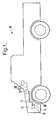
- a vehicle is shown and generally designated 10.
- Figure 1 shows that the vehicle 10 includes an engine 12 that is in fluid communication with an oil reservoir 14, e.g., an oil pan.
- An oil condition sensor 15 is placed within the oil reservoir 14.
- a control module 16 e.g., a vehicle control module (VCM) or body control module (BCM)
- VCM vehicle control module
- BCM body control module
- a warning device 20 e.g., a visual warning device or audible warning device, is electrically connected to the control module 16 via electrical line 22.
- control module 16 can be a microprocessor that includes a series of computer-executable instructions, as described below, which will allow the control module 16 to predict when engine oil in the oil reservoir 14 is contaminated with water and fuel based on the operation of the engine 12. These instructions may reside, for example, in the control module 16, which, when programmed with the present logic, establishes a computer program product.
- the instructions may be contained on a data storage device with a computer readable medium, such as a computer diskette having a data storage medium holding computer program code elements.
- the instructions may be stored on, magnetic tape, conventional hard disk drive, electronic read-only memory, optical storage device, or other appropriate data storage device.
- the computer-executable instructions may be lines of compiled C++ compatible code.
- the logic can be embedded in an application specific integrated circuit (ASIC) chip or other electronic circuitry.
- ASIC application specific integrated circuit
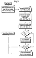
- an IE is an ignition on to off transition, i.e., the engine is running and then, it is turned off.
- the engine run time, t between the present IE and the previous IE is recorded.
- the oil temperature, T oil immediately following the present IE is determined.
- an IE counter is increased by one (1).
- a hot event has occurred and the logic moves to block 46 where a hot event duration (HED) value is set equal to t.
- HED hot event duration
- decision diamond 48 it is determined whether HED is greater than four hours (4 hrs). If so, the logic proceeds to block 50 and FF is set equal to one-half (0.5). The logic then moves to block 54 of Figure 3, described below.
- TWF temperature weight factor
- decision diamond 62 it is determined whether ASC is greater than or equal to CTT. If so, the logic moves to block 64 and a contamination signal is sent from the control module 16 to the warning device 20. The logic then moves to decision diamond 66, described below. At decision diamond 62 if ASC is less than CTT, the logic moves to decision diamond 66 where it is determined whether the engine oil has been changed. If not, the logic returns to block 30 in Figure 2. On the other hand, if the oil has been changed, the logic moves to block 68 where the contamination signal is reset and all relevant logic parameters are reset. The logic then returns to block 30 in Figure 2.
- the method of the present invention can reliably determine when the engine oil has been contaminated by water and fuel based on the operation and run time of the engine 12.
Landscapes
- Engineering & Computer Science (AREA)
- Chemical & Material Sciences (AREA)
- Health & Medical Sciences (AREA)
- Life Sciences & Earth Sciences (AREA)
- Analytical Chemistry (AREA)
- Biochemistry (AREA)
- General Chemical & Material Sciences (AREA)
- Food Science & Technology (AREA)
- Medicinal Chemistry (AREA)
- Physics & Mathematics (AREA)
- Chemical Kinetics & Catalysis (AREA)
- Oil, Petroleum & Natural Gas (AREA)
- General Health & Medical Sciences (AREA)
- General Physics & Mathematics (AREA)
- Immunology (AREA)
- Pathology (AREA)
- Mechanical Engineering (AREA)
- General Engineering & Computer Science (AREA)
- Lubrication Details And Ventilation Of Internal Combustion Engines (AREA)
- Combined Controls Of Internal Combustion Engines (AREA)
Abstract
Description
and
- CER =
- cold events ratio,
- CE =
- number of cold events, and
- IE =
- number of ignition events.
- FF =
- forgettable factor, and
- HED =
- hot event duration (hrs).
- TWF =
- temperature weight factor, and
- Toil =
- temperature of the engine oil following the IE ( C).
- ASC =
- actual state of contamination,
- CER =
- cold event ratio,
- TWFm =
- mean temperature weight factor, and
- FF =
- forgettable factor.
- CTT =
- contamination trigger threshold, and
- ASC =
- actual state of contamination.
Claims (23)
- A method for determining contamination of engine oil comprising the acts of:determining run time of an engine (12);determining an oil temperature;based on the oil temperature, increasing a cold event counter by one;based on the oil temperature, setting a hot event duration value equal to the run time of the engine; andat least partially based on the cold event counter value and the hot event duration value, sending a contamination signal to a warning device (20).
- The method of Claim 1, further comprising the act of:determining an ignition event counter value.
- The method of Claim 2, further comprising the act of:determining a cold event ratio.
- The method of Claim 3, wherein the cold event ratio is determined by CER = (CE/IE) * 100, where CER is the cold event ratio, CE is the cold event counter value, and IE is the ignition event counter value.
- The method of Claim 4, further comprising the act of:based on the hot event duration value determining a forgettable factor.
- The method of Claim 5, wherein the forgettable factor is determined by FF = (-0.142 * HED) + 1.0715, where FF is the forgettable factor and HED is the hot event duration value.
- The method of Claim 6, further comprising the act of:based on the oil temperature, determining temperature weight factor.
- The method of Claim 7, wherein the temperature weight factor is determined by TWF = (-0.0056 * Toil) + 0.88, where TWF is the temperature weight factor and Toil is the oil temperature.
- The method of Claim 8, further comprising the act of:determining the temperature weight factor "n" times.
- The method Claim 9, further comprising the act of:determining the mean of the "n" temperature weight factors.
- The method of Claim 10, further comprising the act of:determining an actual state of contamination value.
- The method of Claim 11, wherein the actual state of contamination value is determined by the equation ASC = (CER * TWFm) * FF, where ASC is the actual state of contamination, CER is the cold event ratio, TWFm is the mean of the "n" temperature weight factors, and FF is the forgettable factor.
- The method of Claim 12, further comprising the act of:determining a contamination trigger threshold.
- The method of Claim 13, wherein the contamination trigger threshold is determined by the equation CTT = (-1.25 * ASC) + 175, where CTT is the contamination trigger threshold and ASC is the actual state of contamination value.
- The method of Claim 14, further comprising the act of:comparing the actual state of contamination value to the contamination trigger threshold.
- The method of Claim 15, further comprising the act of:based on the comparison, sending a contamination signal to a warning device.
- The method of Claim 16, further comprising the act of:resetting the contamination signal when the engine oil is changed.
- An oil sensor apparatus, comprising:at least one oil condition sensor (15); andat least one control module (16) outputting a contamination signal based on a signal from the sensor (15) or based on a default contamination determination based at least in part on cold engine starts.
- The oil sensor apparatus of Claim 18, wherein the sensor (15) is installed within an oil reservoir (14).
- The oil sensor apparatus of Claim 19, further comprising:a warning device (20) electrically connected to the control module (16).
- An oil sensor apparatus, comprising:at least one oil condition sensor (15);at least one control module (16) connected to the oil condition sensor (15), the control module (16) having logic means for determining run time of an engine, logic means for determining an oil temperature, logic means for increasing a cold event counter by one based on the oil temperature, logic means for setting a hot event duration value equal to the run time of the engine based on the oil temperature, and logic means for outputting a contamination signal at least partially based on the cold event counter value and the hot event duration value.
- The oil sensor apparatus of Claim 21, wherein the sensor (15) is installed within an oil reservoir (14).
- The oil sensor apparatus of Claim 22 further comprising:a warning device (20) electrically connected to the control module (16).
Applications Claiming Priority (2)
| Application Number | Priority Date | Filing Date | Title |
|---|---|---|---|
| US150586 | 1988-02-01 | ||
| US10/150,586 US20030213292A1 (en) | 2002-05-17 | 2002-05-17 | Method for determining engine oil contamination |
Publications (2)
| Publication Number | Publication Date |
|---|---|
| EP1363123A2 true EP1363123A2 (en) | 2003-11-19 |
| EP1363123A3 EP1363123A3 (en) | 2005-04-20 |
Family
ID=29269796
Family Applications (1)
| Application Number | Title | Priority Date | Filing Date |
|---|---|---|---|
| EP03076292A Withdrawn EP1363123A3 (en) | 2002-05-17 | 2003-04-29 | Method for predicting engine oil contamination |
Country Status (2)
| Country | Link |
|---|---|
| US (1) | US20030213292A1 (en) |
| EP (1) | EP1363123A3 (en) |
Cited By (4)
| Publication number | Priority date | Publication date | Assignee | Title |
|---|---|---|---|---|
| EP1614870A1 (en) * | 2004-07-06 | 2006-01-11 | Ford Global Technologies, LLC | A method and a counter for predicting a fuel dilution level of an oil in an internal combustion engine |
| WO2009076129A3 (en) * | 2007-12-06 | 2009-08-20 | Gm Global Tech Operations Inc | Virtual engine oil quality sensor |
| US20200063667A1 (en) * | 2016-11-10 | 2020-02-27 | Cpt Group Gmbh | Method and Device for Acquiring the Oil Temperature in an Internal Combustion Engine |
| CN112096482A (en) * | 2019-12-02 | 2020-12-18 | 长城汽车股份有限公司 | Engine oil maintenance control method and device |
Families Citing this family (10)
| Publication number | Priority date | Publication date | Assignee | Title |
|---|---|---|---|---|
| US6494079B1 (en) | 2001-03-07 | 2002-12-17 | Symyx Technologies, Inc. | Method and apparatus for characterizing materials by using a mechanical resonator |
| US7302830B2 (en) * | 2001-06-06 | 2007-12-04 | Symyx Technologies, Inc. | Flow detectors having mechanical oscillators, and use thereof in flow characterization systems |
| US7043969B2 (en) | 2002-10-18 | 2006-05-16 | Symyx Technologies, Inc. | Machine fluid sensor and method |
| AU2003282936A1 (en) | 2002-10-18 | 2004-05-04 | Symyx Technologies, Inc. | Environmental control system fluid sensing system and method comprising a sesnsor with a mechanical resonator |
| US7210332B2 (en) | 2003-03-21 | 2007-05-01 | Symyx Technologies, Inc. | Mechanical resonator |
| DE102004039836B4 (en) * | 2004-08-17 | 2016-06-23 | Continental Automotive Gmbh | Method and device for detecting a fuel input into the lubricating oil of an internal combustion engine |
| US8768599B2 (en) * | 2009-09-16 | 2014-07-01 | GM Global Technology Operations LLC | System and method for engine and fuel system maintenance |
| US9644647B2 (en) | 2013-05-01 | 2017-05-09 | Kepstrum Inc. | High pressure hydraulic contamination injection and control system |
| US10473009B2 (en) * | 2017-01-18 | 2019-11-12 | Vavoline Licensing and Intellectual Property LLC | System and method for predicting remaining oil life in vehicles |
| US11519870B2 (en) * | 2019-08-28 | 2022-12-06 | Pratt & Whitney Canada Corp. | Method and system for determining an exposure temperature of an engine component using lubrication fluid analysis |
Family Cites Families (7)
| Publication number | Priority date | Publication date | Assignee | Title |
|---|---|---|---|---|
| FR2524935B1 (en) * | 1982-04-13 | 1986-02-07 | Exxon France | METHOD AND DEVICE FOR ESTIMATING AND INDICATING THE CONDITION OF WEAR OF THE LUBRICATING OIL OF AN ENGINE |
| DE3663280D1 (en) * | 1985-02-12 | 1989-06-15 | Nissan Motor | Oil degradation warning system |
| JPS61207810A (en) * | 1985-03-12 | 1986-09-16 | Nissan Motor Co Ltd | Engine-oil replacing time alarming apparatus |
| US4677847A (en) * | 1985-09-30 | 1987-07-07 | Aisin Seiki Kabushiki Kaisha | Automotive engine oil monitoring system |
| JPH0665844B2 (en) * | 1985-11-15 | 1994-08-24 | 日産自動車株式会社 | Lubricant replacement warning device for vehicles |
| US5060156A (en) * | 1989-07-20 | 1991-10-22 | Ford Motor Company | Method and apparatus for determining engine oil change intervals according to actual engine use |
| US4970492A (en) * | 1990-02-08 | 1990-11-13 | Ford Motor Company | Method and apparatus for determining excessive engine oil usage |
-
2002
- 2002-05-17 US US10/150,586 patent/US20030213292A1/en not_active Abandoned
-
2003
- 2003-04-29 EP EP03076292A patent/EP1363123A3/en not_active Withdrawn
Cited By (7)
| Publication number | Priority date | Publication date | Assignee | Title |
|---|---|---|---|---|
| EP1614870A1 (en) * | 2004-07-06 | 2006-01-11 | Ford Global Technologies, LLC | A method and a counter for predicting a fuel dilution level of an oil in an internal combustion engine |
| WO2009076129A3 (en) * | 2007-12-06 | 2009-08-20 | Gm Global Tech Operations Inc | Virtual engine oil quality sensor |
| US8179242B2 (en) | 2007-12-06 | 2012-05-15 | GM Global Technology Operations LLC | Virtual engine oil quality sensor |
| US20200063667A1 (en) * | 2016-11-10 | 2020-02-27 | Cpt Group Gmbh | Method and Device for Acquiring the Oil Temperature in an Internal Combustion Engine |
| US10781730B2 (en) * | 2016-11-10 | 2020-09-22 | Vitesco Technologies GmbH | Method and device for acquiring the oil temperature in an internal combustion engine |
| CN112096482A (en) * | 2019-12-02 | 2020-12-18 | 长城汽车股份有限公司 | Engine oil maintenance control method and device |
| CN112096482B (en) * | 2019-12-02 | 2022-05-03 | 长城汽车股份有限公司 | Engine oil maintenance control method and device |
Also Published As
| Publication number | Publication date |
|---|---|
| US20030213292A1 (en) | 2003-11-20 |
| EP1363123A3 (en) | 2005-04-20 |
Similar Documents
| Publication | Publication Date | Title |
|---|---|---|
| US20030213292A1 (en) | Method for determining engine oil contamination | |
| US5848381A (en) | Decision system for determining sensor failure of temperature sensor in automobile applications | |
| CN100429435C (en) | Method of detecting failure of oil temperature sensor for automatic transmission | |
| US20030083825A1 (en) | Method for continuously predicting remaining engine oil life | |
| CA2017400C (en) | Method and apparatus for determining engine oil change intervals according to actual engine use | |
| US8223060B2 (en) | Electric control system and electric control unit | |
| US6508100B2 (en) | System and method for resetting vehicle engine oil sensors | |
| JP2000087832A (en) | Reverse drive control device for motorcycle | |
| US9804037B2 (en) | Diagnostic apparatus for temperature sensor | |
| FR2909714A1 (en) | METHOD AND DEVICE FOR MANAGING TRAINING UNITS. | |
| US8853986B2 (en) | Method and device for diagnosing a fan | |
| US20060149441A1 (en) | Failure detection device and method for oil temperature sensor for automatic transmission | |
| US20050155574A1 (en) | Ice-breaking, autozero and frozen throttle plate detection at power-up for electronic motorized throttle | |
| WO2013191619A1 (en) | Diagnostics for a starter motor | |
| US6915681B2 (en) | Gear-shift control device and gear-shift control method for automatic transmission | |
| JPH0979037A (en) | Abnormality detection device for radiator cooling fan system | |
| US7706939B2 (en) | Data recording apparatus and shut-down method for data recording apparatus | |
| US7100570B2 (en) | Throttle control system and method | |
| EP1571599B1 (en) | Data recording apparatus and the method thereof | |
| US20020141122A1 (en) | Apparatus and method for protecting starter for engine against overheating | |
| KR20050099991A (en) | Diagnostic method for a sensor | |
| JP2515817B2 (en) | Starting heating device for stepping motors | |
| US6688270B2 (en) | Apparatus and method for preventing overrun of starter for engine | |
| EP1710462A1 (en) | Clutch slip protection | |
| JPH09329222A (en) | Failure determination device for oil temperature detection means of automatic transmission |
Legal Events
| Date | Code | Title | Description |
|---|---|---|---|
| PUAI | Public reference made under article 153(3) epc to a published international application that has entered the european phase |
Free format text: ORIGINAL CODE: 0009012 |
|
| AK | Designated contracting states |
Kind code of ref document: A2 Designated state(s): AT BE BG CH CY CZ DE DK EE ES FI FR GB GR HU IE IT LI LU MC NL PT RO SE SI SK TR |
|
| AX | Request for extension of the european patent |
Extension state: AL LT LV MK |
|
| PUAL | Search report despatched |
Free format text: ORIGINAL CODE: 0009013 |
|
| AK | Designated contracting states |
Kind code of ref document: A3 Designated state(s): AT BE BG CH CY CZ DE DK EE ES FI FR GB GR HU IE IT LI LU MC NL PT RO SE SI SK TR |
|
| AX | Request for extension of the european patent |
Extension state: AL LT LV MK |
|
| AKX | Designation fees paid | ||
| REG | Reference to a national code |
Ref country code: DE Ref legal event code: 8566 |
|
| STAA | Information on the status of an ep patent application or granted ep patent |
Free format text: STATUS: THE APPLICATION IS DEEMED TO BE WITHDRAWN |
|
| 18D | Application deemed to be withdrawn |
Effective date: 20051101 |