EP1363121A1 - Scatter correction method for non-stationary x-ray acquisitions - Google Patents
Scatter correction method for non-stationary x-ray acquisitions Download PDFInfo
- Publication number
- EP1363121A1 EP1363121A1 EP03251593A EP03251593A EP1363121A1 EP 1363121 A1 EP1363121 A1 EP 1363121A1 EP 03251593 A EP03251593 A EP 03251593A EP 03251593 A EP03251593 A EP 03251593A EP 1363121 A1 EP1363121 A1 EP 1363121A1
- Authority
- EP
- European Patent Office
- Prior art keywords
- scatter
- radiation
- detector
- image
- incident
- Prior art date
- Legal status (The legal status is an assumption and is not a legal conclusion. Google has not performed a legal analysis and makes no representation as to the accuracy of the status listed.)
- Withdrawn
Links
Images





Classifications
-
- G—PHYSICS
- G06—COMPUTING OR CALCULATING; COUNTING
- G06T—IMAGE DATA PROCESSING OR GENERATION, IN GENERAL
- G06T12/00—Tomographic reconstruction from projections
- G06T12/10—Image preprocessing, e.g. calibration, positioning of sources or scatter correction
-
- G—PHYSICS
- G01—MEASURING; TESTING
- G01N—INVESTIGATING OR ANALYSING MATERIALS BY DETERMINING THEIR CHEMICAL OR PHYSICAL PROPERTIES
- G01N23/00—Investigating or analysing materials by the use of wave or particle radiation, e.g. X-rays or neutrons, not covered by groups G01N3/00 – G01N17/00, G01N21/00 or G01N22/00
- G01N23/02—Investigating or analysing materials by the use of wave or particle radiation, e.g. X-rays or neutrons, not covered by groups G01N3/00 – G01N17/00, G01N21/00 or G01N22/00 by transmitting the radiation through the material
- G01N23/04—Investigating or analysing materials by the use of wave or particle radiation, e.g. X-rays or neutrons, not covered by groups G01N3/00 – G01N17/00, G01N21/00 or G01N22/00 by transmitting the radiation through the material and forming images of the material
- G01N23/046—Investigating or analysing materials by the use of wave or particle radiation, e.g. X-rays or neutrons, not covered by groups G01N3/00 – G01N17/00, G01N21/00 or G01N22/00 by transmitting the radiation through the material and forming images of the material using tomography, e.g. computed tomography [CT]
-
- G—PHYSICS
- G01—MEASURING; TESTING
- G01N—INVESTIGATING OR ANALYSING MATERIALS BY DETERMINING THEIR CHEMICAL OR PHYSICAL PROPERTIES
- G01N2223/00—Investigating materials by wave or particle radiation
- G01N2223/40—Imaging
- G01N2223/419—Imaging computed tomograph
Definitions
- the present invention relates generally to scatter-correction for X-ray or the like type of examination technique, and more specifically to a scatter-correction technique for situations wherein the angle of incidence of an incident ray from a radiation source impinges on a detector at an angle which is not exactly zero degrees or exactly at right angles to the detector, and thus allows for the source to be moved with respect to the detector or vice versa.
- Breast cancer is a significant cause of mortality among women in the United States.
- Currently the most widespread breast-cancer screening technique is X-ray mammography, where malignancies are detected based on their characteristic shape (typically spiculated) and radiological density (similar to breast glandular tissue).
- Tomosynthesis is a promising alternative to conventional two-dimensional mammography.
- This imaging technique resides in the acquisition of plural low-dose 2D X-ray projection images, where the X-ray source is moved along an arcuate trajectory with respect to the stationary breast and/or detector. X-ray projections are thus acquired at different angles. These angular projections are then combined in a 3D image reconstruction of the breast. In the reconstructed image, the overlap of 3D structures is mitigated, contrast is enhanced and the morphological features of malignancies (spiculation) can be better preserved than in 2D X-ray imaging, therefore leading to improved sensitivity and specificity with respect to 2D X-ray mammography.
- a first aspect of the present invention resides in a method of estimating scatter in an image, where radiation from a radiation source is transmitted through an object to be imaged and is incident on a detector at an inclined or "non-zero" angle.
- This method comprises explicitly modeling an effect of angular incidence of the radiation on a scatter signal, including deriving, using an empirically based correction which includes the effect of a non-zero angle of incidence of the radiation on the detector, an estimate of the scatter signal in image data derived from the incident radiation on the detector.
- a second aspect of the invention resides in a method of calculating and removing scatter from an image, where radiation emitted from a source is transmitted through an imaged object, is incident on a detector at a non-zero (acute) angle, comprising: explicitly modeling the effect of angular incidence of radiation in a scatter signal; re-normalizing the scatter signal depending on the angle of incidence of radiation and the thickness of the object imaged; and correction of scatter from an image based on inverse-filtering.
- a third aspect of the invention resides in a method of estimating scatter in an X-ray image, where radiation emitted from an X-ray source is transmitted through an imaged object and is incident on the X-ray detector at an acute or non-zero angle, comprising: explicitly modeling the effect of angular incidence of X-ray radiation in a scatter signal; and calculating, via convolution, an estimate of the scatter signal in an X-ray image.
- a fourth aspect of the invention resides in a method of estimating an asymmetrical scatter kernel wherein asymmetry is introduced by angular incidence of radiation, which has been emitted from a source and transmitted through an object to be imaged, on a detector, comprising: modifying scatter that would be derived wherein the radiation is directly incident on the detector with zero degrees of inclination, using an asymmetry factor which indicates the shape and magnitude of the scatter kernel and which varies with an angle at which the radiation is incident on the detector, a mean attenuation coefficient of the object, and a distance the radiation has traveled through the object.
- the present invention is directed to a scatter-correction technique which enables the angle of the incident radiation to be taken into account and thus includes the relative position between the radiation source and the radiation detector arrangement which receives the radiation in the calculation and corrrection for scatter. It will be noted that the angle of incidence can very closely approach zero degrees (viz., exactly parallel to the normal of the detector plane and thus effectively encompass all angles which are encountered and in which scattering occurs and needs to be either determined and/or corrected for.
- FIG 1 is a schematic representation of an imaging system 10, such as conventionally used in X-ray mammography imaging and tomosynthesis imaging.
- This system 10 includes at least one radiation source 14, such as an X-ray source, and at least one detector array 16 for receiving radiation emitted from the radiation source at one or more projection angles.
- This system can be adapted, for example, so that the radiation source 14 projects a cone-shaped beam of X-rays which pass through object 12 and impinge on the detector array 16.
- the detector array 16 has a plurality of detector elements (not shown per se) arranged in rows and columns such that image data of the object 12 of interest can be suitably collected.
- the detector elements can each comprise one or more photosensors, such as photodiodes.
- the radiation which is incident on a scintillator material enables the photosensors to measure, by way of change in the charge across the diode(s), an amount of light generated by X-ray interaction with the scintillator.
- This control mechanism 28 includes a radiation controller 30 that provides power and timing signals to the radiation source 14 and a motor controller 32 that controls a respective movement speed and position of radiation source 14 and detector array 16.
- a data acquisition system (DAS) 34 which is included in the control mechanism 28 samples digital data from detector 16 for subsequent processing.
- An image processor 36 receives a sampled and digitized projection data set from DAS 34 and performs image processing and scatter correction, as described herein.
- a system controller 38 such as a computer or a microprocessor control the other elements of the system 10.
- Figure 2 is a diagram which demonstrates the various parameters in which following equations are couched.
- Figure 3 is a schematic perspective view of an experimental arrangement which was used to conduct tests to verify the voracity of the effect of the algorithm that can implement the estimations enabled using the techniques outlined below. In this arrangement, a plurality of acrylic plates are disposed one on top of the other.
- This arrangement radiologicially approximates tissue such as breast tissue and thus enables a mammographic simulation.
- the arrangement is intended to represent, merely by way of example, a compressed breast thickness, which is included along with a detector cover thickness and a compression paddle thickness. This enables a thickness value to be determined and used in calculations to determine a length of the path along which a ray has passed and which length is used in the disclosed embodiment of the scatter correction process.
- a mammography image can be thought of as formed by unattenuated X-ray photons arriving directly from the source (direct events), plus photons that scatter into the detector from the breast and the acquisition system.
- the scatter kernel p can be though of as the probability that an X-ray photon directed onto pixel k of the detector will actually be scattered into pixel j .
- Equation 3 Equation 3
- the angular incidence of the X-ray photons introduces an asymmetry in the original scatter kernel p jk .
- the angular incidence of radiation introduces an asymmetry in the scatter kernel, as explained in the previous section.
- the magnitude of the kernel changed in a manner that was unaccounted for by the simple increase of path length l' k of photons through the imaged object as a function of ⁇ .
- This introduces an empirical normalization function f(t, ⁇ ) , which is determined by a series of measurements spanning object thicknesses t from 1 to 8 cm and radiation incidence angles from 0° to 45°.
- the slit collimator image was taken as shown in Figure 3.
- the slit collimator was made of a sheet of Tungsten with a thickness of 20 mils. A 1 mm wide slit allowed X-rays through. The signal directly beneath the slit is effectively scatter-free.
- An open-geometry image was acquired in the same way as the slit collimator image, except that the collimator was removed, thus allowing for scatter in the image.
- the scatter-free signal b k acquired in the slit-collimator image was then compared to the scatter-corrected open-geometry signal b' k by calculating the reduced chi-squared ⁇ 2 between the scatter-free and scatter-corrected signals;
- An empirical kernel normalization factor was determined by minimizing ⁇ 2 for a given t and ⁇ .
- a surface function f(t, ⁇ ) was then generated by regression.
- Experimental data were acquired using a prototype tomosynthesis X-ray system for mammography.
- Three anthropomorphic breast phantoms were used for validation of the scatter-correction technique, with nominal thickness of 4, 5 and 6 cm. Their glandular/fat percent composition was 50/50, 70/30 and 80/20, respectively.
- a full set of projections (11 images) were acquired for slit collimator and open geometry for each phantom. Each set of projections covered tube angles ranging from +25° to -25° in 5° steps.
- the technique used was Rh/Rh, 32 kVp and 10 mAs per projection image.
- the open-geometry projections were scatter-corrected using the new scatter kernel p' jk , and compared to the scatter-free signal acquired using the slit collimator.
- Figures. 3-8 show the open-geometry, scatter-free and scatter corrected signals for pixels directly below collimator slit. As will be appreciated, these figures show a comparison between open-geometry (y k ), scatter-free (b k ) and scatter-corrected (b' k ) signals for a 25° angular acquisition. The mean difference between the scatter-free and scatter-corrected is less than ⁇ 3%.
- the scatter-corrected projections obtained with the present invention are comparable with the nearly scatter-free signal obtained using a slit collimator.
- Experimental data shows that the mean percent difference between the scatter corrected and the scatter-free projection signal is less than 3% in all cases, even in the edge region where there is rapid change in the thickness of the breast phantoms.
- this table shows the bias and standard deviation of the scatter-free signal and the open-geometry signal with and without scatter correction and highlights the effectiveness of the technique.
Landscapes
- Physics & Mathematics (AREA)
- General Physics & Mathematics (AREA)
- Engineering & Computer Science (AREA)
- Theoretical Computer Science (AREA)
- Health & Medical Sciences (AREA)
- Nuclear Medicine, Radiotherapy & Molecular Imaging (AREA)
- Pulmonology (AREA)
- Radiology & Medical Imaging (AREA)
- Life Sciences & Earth Sciences (AREA)
- Chemical & Material Sciences (AREA)
- Analytical Chemistry (AREA)
- Biochemistry (AREA)
- General Health & Medical Sciences (AREA)
- Immunology (AREA)
- Pathology (AREA)
- Apparatus For Radiation Diagnosis (AREA)
Abstract
Description
- The present invention relates generally to scatter-correction for X-ray or the like type of examination technique, and more specifically to a scatter-correction technique for situations wherein the angle of incidence of an incident ray from a radiation source impinges on a detector at an angle which is not exactly zero degrees or exactly at right angles to the detector, and thus allows for the source to be moved with respect to the detector or vice versa.
- Breast cancer is a significant cause of mortality among women in the United States. Currently the most widespread breast-cancer screening technique is X-ray mammography, where malignancies are detected based on their characteristic shape (typically spiculated) and radiological density (similar to breast glandular tissue).
- Early detection of breast cancer generally improves a patient's chance of survival and is thus of critical importance. The task of detection of malignancies is complicated by the fact that the breast is a radiologically complex 3D structure that is imaged by 2D X-ray projection. Thus, malignant lesions can be masked by surrounding glandular tissue, decreasing contrast and distorting the lesion's perceived shape. A significant number of malignancies are missed in mammography because of the presence of this increase of structural noise brought about by the projection of 3D structures in the breast onto a 2D image.
- Tomosynthesis is a promising alternative to conventional two-dimensional mammography. This imaging technique resides in the acquisition of plural low-dose 2D X-ray projection images, where the X-ray source is moved along an arcuate trajectory with respect to the stationary breast and/or detector. X-ray projections are thus acquired at different angles. These angular projections are then combined in a 3D image reconstruction of the breast. In the reconstructed image, the overlap of 3D structures is mitigated, contrast is enhanced and the morphological features of malignancies (spiculation) can be better preserved than in 2D X-ray imaging, therefore leading to improved sensitivity and specificity with respect to 2D X-ray mammography.
- In tomosynthesis, the use of a non-stationary X-ray source precludes the use of a traditional grid for scatter rejection. With larger source angles with respect to the detector normal, the scatter signal will increase due to the longer distances that the X-rays traverse through the breast tissue. Therefore, there is a need to be able to estimate the scatter component on an X-ray image that has been acquired and compensate for the scattering in order to improve the resolution/effectiveness of the examination of the breast tissue.
- More specifically, a first aspect of the present invention resides in a method of estimating scatter in an image, where radiation from a radiation source is transmitted through an object to be imaged and is incident on a detector at an inclined or "non-zero" angle. This method comprises explicitly modeling an effect of angular incidence of the radiation on a scatter signal, including deriving, using an empirically based correction which includes the effect of a non-zero angle of incidence of the radiation on the detector, an estimate of the scatter signal in image data derived from the incident radiation on the detector.
- A second aspect of the invention resides in a method of calculating and removing scatter from an image, where radiation emitted from a source is transmitted through an imaged object, is incident on a detector at a non-zero (acute) angle, comprising: explicitly modeling the effect of angular incidence of radiation in a scatter signal; re-normalizing the scatter signal depending on the angle of incidence of radiation and the thickness of the object imaged; and correction of scatter from an image based on inverse-filtering.
- A third aspect of the invention resides in a method of estimating scatter in an X-ray image, where radiation emitted from an X-ray source is transmitted through an imaged object and is incident on the X-ray detector at an acute or non-zero angle, comprising: explicitly modeling the effect of angular incidence of X-ray radiation in a scatter signal; and calculating, via convolution, an estimate of the scatter signal in an X-ray image.
- A fourth aspect of the invention resides in a method of estimating an asymmetrical scatter kernel wherein asymmetry is introduced by angular incidence of radiation, which has been emitted from a source and transmitted through an object to be imaged, on a detector, comprising: modifying scatter that would be derived wherein the radiation is directly incident on the detector with zero degrees of inclination, using an asymmetry factor which indicates the shape and magnitude of the scatter kernel and which varies with an angle at which the radiation is incident on the detector, a mean attenuation coefficient of the object, and a distance the radiation has traveled through the object.
- Further aspects of the invention respectively reside in computer readable media which are encoded with programs executable by a computer for implementing the above mentioned methods. Additionally imaging systems which include hardware and computer software and which are adapted to implement the above mentioned methods, also comprise further aspect of the invention.
- The invention will now be described in greater detail, by way of example, with reference to the drawings, in which:-
- Figure 1 is a schematic representation of an example of an X-ray system that the embodiments of the present invention can be applied.
- Figure 2 is a diagram which depicts the foundation of equations 1 - 14.
- Figure 3 is a schematic perspective view showing an experimental setup for angular measurements of scattered radiation.
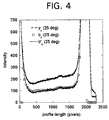
- Figures 4 - 9 are graphical comparison between open-geometry (yk), scatter-free (bk) and scatter-corrected (b'k) signals for a 25° angular acquisition.
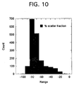
- Figures 10 and 11 are histograms wherein the histogram of Fig. 10 shows the percent deviation between the scatter-free signal and the open geometry signal within the 5 cm breast phantom (25° acquisition), and Fig. 11 shows, after scatter correction, the percent deviation between the scatter-free signal and the scatter corrected signal within the 5 cm breast phantom (25° acquisition).
-
- The present invention is directed to a scatter-correction technique which enables the angle of the incident radiation to be taken into account and thus includes the relative position between the radiation source and the radiation detector arrangement which receives the radiation in the calculation and corrrection for scatter. It will be noted that the angle of incidence can very closely approach zero degrees (viz., exactly parallel to the normal of the detector plane and thus effectively encompass all angles which are encountered and in which scattering occurs and needs to be either determined and/or corrected for.
- Before dealing with the concept on which the present invention is based, it is appropriate to consider an example of the type of device to which the concept of the invention can be applied.
- Figure 1 is a schematic representation of an
imaging system 10, such as conventionally used in X-ray mammography imaging and tomosynthesis imaging. Thissystem 10 includes at least oneradiation source 14, such as an X-ray source, and at least onedetector array 16 for receiving radiation emitted from the radiation source at one or more projection angles. This system can be adapted, for example, so that theradiation source 14 projects a cone-shaped beam of X-rays which pass throughobject 12 and impinge on thedetector array 16. - The
detector array 16 has a plurality of detector elements (not shown per se) arranged in rows and columns such that image data of theobject 12 of interest can be suitably collected. As is conventional the detector elements can each comprise one or more photosensors, such as photodiodes. The radiation which is incident on a scintillator material enables the photosensors to measure, by way of change in the charge across the diode(s), an amount of light generated by X-ray interaction with the scintillator. - Simply by way of explanation, the operation of
radiation source 14 is governed by acontrol mechanism 28 of theimaging system 10. Thiscontrol mechanism 28 includes aradiation controller 30 that provides power and timing signals to theradiation source 14 and amotor controller 32 that controls a respective movement speed and position ofradiation source 14 anddetector array 16. - A data acquisition system (DAS) 34 which is included in the
control mechanism 28 samples digital data fromdetector 16 for subsequent processing. Animage processor 36 receives a sampled and digitized projection data set fromDAS 34 and performs image processing and scatter correction, as described herein. Asystem controller 38, such as a computer or a microprocessor control the other elements of thesystem 10. - Figure 2 is a diagram which demonstrates the various parameters in which following equations are couched. Figure 3, on the other hand, is a schematic perspective view of an experimental arrangement which was used to conduct tests to verify the voracity of the effect of the algorithm that can implement the estimations enabled using the techniques outlined below. In this arrangement, a plurality of acrylic plates are disposed one on top of the other.
- This arrangement radiologicially approximates tissue such as breast tissue and thus enables a mammographic simulation. Although not specifically indicated, the arrangement is intended to represent, merely by way of example, a compressed breast thickness, which is included along with a detector cover thickness and a compression paddle thickness. This enables a thickness value to be determined and used in calculations to determine a length of the path along which a ray has passed and which length is used in the disclosed embodiment of the scatter correction process.
- A mammography image can be thought of as formed by unattenuated X-ray photons arriving directly from the source (direct events), plus photons that scatter into the detector from the breast and the acquisition system. The measured image y is then defined as
- From
Equations 1 and 2 we havewhere the index k spans all pixels of the detector (1 through N).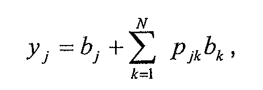
- Assuming that p is known for a given image acquisition system configuration and object being imaged, we can make an initial estimation of the scatter signal through the expression
y p is the scatter kernel norm. RearrangingEquation 1 we can write an initial estimate of the direct eventsp < 2 l in order to insure convergence. - The angular incidence of the X-ray photons introduces an asymmetry in the original scatter kernel pjk . Originally, if the angle of incidence between the X-ray and the normal to the detector surface is zero degrees, the probability of a photon from ray k to scatter and be detected in pixel j, is assumed symmetric and spatially invariant with respect to the indices k and j, so the kernel could be written explicitly as pj-k . Therefore the kernel p depends only on the relative distances between pixels k and j. This symmetry is readily seen in Figure 2, where the kernel pjk = pj'k . However, if the angle of incidence of the radiation is α ≠ 0, then the length of the photon path from the point of scatter is different for pixels j and j'. Consequently the probability of transmission of the X-ray photons scattered into pixels j and j' will differ and in general p'jk ≠ p'j'k .
- We introduce a correction factor which relates the scatter kernels at zero degrees with the angular scatter kernel so that
- Pjk is the shape and magnitude of the scatter at zero degrees;
- N is an empirically determined normalization factor; and
- ωjk is an asymmetry factor given by
-
- Distance r is given by
- The distance r' is given by
- The estimated height z (perpendicular distance) can be obtained from the expression for z' by setting α = 0.
- The normalization factor N is given bywhere f(t,α) is an empirically-determined scatter-kernel normalization factor that depends on the thickness of the object imaged and the angle of the radiation source with respect to the normal of the detector plane. Equation 6 then remains
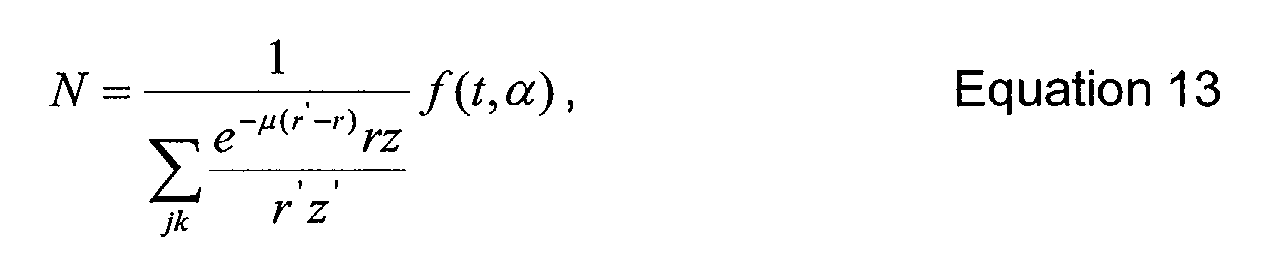
- The angular incidence of radiation introduces an asymmetry in the scatter kernel, as explained in the previous section. In addition, the magnitude of the kernel changed in a manner that was unaccounted for by the simple increase of path length l'k of photons through the imaged object as a function of α. This introduces an empirical normalization function f(t,α), which is determined by a series of measurements spanning object thicknesses t from 1 to 8 cm and radiation incidence angles from 0° to 45°.
- Two images were taken for any given object thickness t and incident X-ray angle α: The slit collimator image was taken as shown in Figure 3. The slit collimator was made of a sheet of Tungsten with a thickness of 20 mils. A 1 mm wide slit allowed X-rays through. The signal directly beneath the slit is effectively scatter-free.
- An open-geometry image was acquired in the same way as the slit collimator image, except that the collimator was removed, thus allowing for scatter in the image.
- The scatter-free signal bk acquired in the slit-collimator image was then compared to the scatter-corrected open-geometry signal b'k by calculating the reduced chi-squared χ2 between the scatter-free and scatter-corrected signals;

- An empirical kernel normalization factor was determined by minimizing χ2 for a given t and α. A surface function f(t, α) was then generated by regression.
- Experimental data were acquired using a prototype tomosynthesis X-ray system for mammography. Three anthropomorphic breast phantoms were used for validation of the scatter-correction technique, with nominal thickness of 4, 5 and 6 cm. Their glandular/fat percent composition was 50/50, 70/30 and 80/20, respectively. A full set of projections (11 images) were acquired for slit collimator and open geometry for each phantom. Each set of projections covered tube angles ranging from +25° to -25° in 5° steps. The technique used was Rh/Rh, 32 kVp and 10 mAs per projection image.
- The open-geometry projections were scatter-corrected using the new scatter kernel p'jk , and compared to the scatter-free signal acquired using the slit collimator.
- Figures. 3-8 show the open-geometry, scatter-free and scatter corrected signals for pixels directly below collimator slit. As will be appreciated, these figures show a comparison between open-geometry (yk), scatter-free (bk) and scatter-corrected (b'k) signals for a 25° angular acquisition. The mean difference between the scatter-free and scatter-corrected is less than ∼3%.
- In the histogram shown in Figure 10, the % deviation between the scatter-free signal and the open geometry signal within the 5 cm breast phantom (25° acquisition) is shown. After scatter correction the percent deviation between the scatter-free signal and the scatter corrected signal within the 5 cm breast phantom (25° acquisition) is show in the histogram of Fig. 10.

- As will be appreciated, the scatter-corrected projections obtained with the present invention are comparable with the nearly scatter-free signal obtained using a slit collimator. Experimental data shows that the mean percent difference between the scatter corrected and the scatter-free projection signal is less than 3% in all cases, even in the edge region where there is rapid change in the thickness of the breast phantoms.
- As will be appreciated, this table shows the bias and standard deviation of the scatter-free signal and the open-geometry signal with and without scatter correction and highlights the effectiveness of the technique.
- Reference is made to an article entitled Digital Tomosynthesis in Breast Imaging by Loren T. Niklason et al., Radiology. 205(2), 1997 p 399-406.
- Reference is made to copending United States Patent Application No. 10/062,338 (Attorney Docket No. RD 28622) entitled METHODS AND APPARATUS FOR CORRECTING SCATTER.
- While the invention has been described in connection with a tomographical examination using X-rays, it will be understood that the estimation of scatter concept on which the present invention is based, is not limited to the use of X-rays nor living tissue and can be applied to inanimate objects such as aircraft wings or the like carried out using any suitable radiation source such as a gamma or electron beam source.
Claims (10)
- A method of estimating scatter in an image, where radiation from a radiation source (14) is transmitted through an object (12) to be imaged and is incident on a detector (16) at an inclined angle, comprising the steps of explicitly modeling an effect of angular incidence of the radiation on a scatter signal, including deriving, using an empirically based correction which includes the effect of an angle of incidence of the radiation on the detector, an estimate of the scatter signal in image data derived from the incident radiation on the detector.
- A method as set forth in claim 1, further comprising the step of calibrating the scatter signal depending on an angle of incidence of radiation and a thickness of the imaged object (12).
- A method as set forth in claim 1 or 2, further comprising the step of re-normalizing the scatter signal depending on an angle of incidence of radiation and a thickness of the imaged object (12).
- A method as set forth in claim 1, 2 or 3, further comprising the step of correcting scatter from the image using inverse-filtering.
- A method as set forth in any preceding claim, further comprising the step of subtracting the estimate of the scatter signal from a total image derived using data based on the radiation incident on the detector (16), to obtain an image which is scatter corrected.
- A method of calculating and removing scatter from an image, where radiation emitted from a source (14) is transmitted through an imaged object (12), is incident on a detector (16) at an acute angle, comprising:explicitly modeling the effect of angular incidence of radiation in a scatter signal;re-normalizing the scatter signal depending on the angle of incidence of radiation and the thickness of the object (12) imaged; andcorrecting scatter from an image based on inverse-filtering.
- A method of estimating scatter in an X-ray image, where radiation emitted from an X-ray source (14) is transmitted through an imaged object (12) and is incident on the X-ray detector (16) at an acute angle, comprising:explicitly modeling the effect of angular incidence of X-ray radiation in a scatter signal; andcalculating, via convolution, an estimate of the scatter signal in an X-ray image.
- A method of estimating an asymmetrical scatter kernel wherein asymmetry is introduced by angular incidence of radiation, which has been emitted from a source (14) and transmitted through an object (12) to be imaged, on a detector (16), comprising modifying scatter that would be derived wherein the radiation is directly incident on the detector with zero degrees of inclination, using an asymmetry factor which indicates the shape and magnitude of the scatter kernel and which varies with an angle at which the radiation is incident on the detector (16), a mean attenuation coefficient of the object (12), and a distance the radiation has traveled through the object.
- A computer readable medium encoded with a program executable by a computer (38), said program being configured to instruct the computer to perform the method of claims 1, 6, 7 or 8.
- An imaging system (10) comprising:wherein the imaging system (10) is configured to perform the method of claims 1, 6, 7 or 8.a radiation source (14) and a detector array (16), wherein the radiation source and the detector array are movable relative to one another;a computer (38) coupled to the detector array (16);
Applications Claiming Priority (2)
| Application Number | Priority Date | Filing Date | Title |
|---|---|---|---|
| US10/063,806 US6748047B2 (en) | 2002-05-15 | 2002-05-15 | Scatter correction method for non-stationary X-ray acquisitions |
| US63806 | 2002-05-15 |
Publications (1)
| Publication Number | Publication Date |
|---|---|
| EP1363121A1 true EP1363121A1 (en) | 2003-11-19 |
Family
ID=29268590
Family Applications (1)
| Application Number | Title | Priority Date | Filing Date |
|---|---|---|---|
| EP03251593A Withdrawn EP1363121A1 (en) | 2002-05-15 | 2003-03-14 | Scatter correction method for non-stationary x-ray acquisitions |
Country Status (2)
| Country | Link |
|---|---|
| US (1) | US6748047B2 (en) |
| EP (1) | EP1363121A1 (en) |
Cited By (3)
| Publication number | Priority date | Publication date | Assignee | Title |
|---|---|---|---|---|
| WO2007148263A1 (en) * | 2006-06-22 | 2007-12-27 | Philips Intellectual Property & Standards Gmbh | Method and system for error compensation |
| US8000435B2 (en) | 2006-06-22 | 2011-08-16 | Koninklijke Philips Electronics N.V. | Method and system for error compensation |
| US8488902B2 (en) | 2009-01-29 | 2013-07-16 | Koninklijke Philips Electronics N.V. | Detection values correction apparatus |
Families Citing this family (30)
| Publication number | Priority date | Publication date | Assignee | Title |
|---|---|---|---|---|
| US6941323B1 (en) * | 1999-08-09 | 2005-09-06 | Almen Laboratories, Inc. | System and method for image comparison and retrieval by enhancing, defining, and parameterizing objects in images |
| JP4149230B2 (en) * | 2002-10-16 | 2008-09-10 | 富士フイルム株式会社 | Radiographic imaging system and radiographic image detector |
| US10638994B2 (en) | 2002-11-27 | 2020-05-05 | Hologic, Inc. | X-ray mammography with tomosynthesis |
| JP4334244B2 (en) * | 2003-02-13 | 2009-09-30 | 株式会社東芝 | Biplane X-ray equipment |
| EP1618411A4 (en) * | 2003-04-11 | 2012-04-25 | Fischer Imaging Corp | DISCHARGE REJECTION FOR COMPOSITE MEDICAL IMAGING SYSTEMS |
| US7020240B2 (en) * | 2003-12-31 | 2006-03-28 | General Electric Company | Method and apparatus for measuring matter properties |
| US7646902B2 (en) * | 2005-02-08 | 2010-01-12 | Regents Of The University Of Michigan | Computerized detection of breast cancer on digital tomosynthesis mammograms |
| US7208739B1 (en) | 2005-11-30 | 2007-04-24 | General Electric Company | Method and apparatus for correction of pileup and charge sharing in x-ray images with energy resolution |
| US20080023636A1 (en) * | 2006-07-25 | 2008-01-31 | Samir Chowdhury | Tungsten polymer collimator for medical imaging |
| US20090082637A1 (en) * | 2007-09-21 | 2009-03-26 | Michael Galperin | Multi-modality fusion classifier with integrated non-imaging factors |
| US8144829B2 (en) * | 2008-02-27 | 2012-03-27 | The Board Of Trustees Of The Leland Stanford Junior University | Cone-beam CT imaging scheme |
| US8326011B2 (en) * | 2008-05-21 | 2012-12-04 | Varian Medical Systems, Inc. | Methods, systems, and computer-program products for estimating scattered radiation in radiographic projections |
| US9001961B2 (en) | 2008-05-21 | 2015-04-07 | Varian Medical Systems, Inc. | Methods of scatter correction of X-ray projection data 1 |
| US8017914B2 (en) * | 2008-11-13 | 2011-09-13 | General Electric Company | Method and system for scatter correction |
| US20110142367A1 (en) * | 2009-12-15 | 2011-06-16 | Charles William Stearns | Methods and systems for correcting image scatter |
| US8199873B2 (en) | 2010-04-15 | 2012-06-12 | Varian Medical Systems Inc. | Methods of scatter correction of x-ray projection data 2 |
| KR101687971B1 (en) * | 2010-07-19 | 2016-12-21 | 삼성전자주식회사 | Apparatus and method for checking breast cancer |
| FR2966716B1 (en) | 2010-10-29 | 2012-12-21 | Gen Electric | METHOD OF ESTIMATING AND CORRECTION OF DIFFUSION IN MAMMOGRAPHY. |
| US20120143083A1 (en) * | 2010-12-01 | 2012-06-07 | Andrew Kwai | Devices and methods for improving the usability of stereotactic imaging for performing a breast biopsy |
| US8989469B2 (en) | 2010-12-20 | 2015-03-24 | The Board Of Trustees Of The Leland Stanford Junior University | Systems and methods for simultaneous acquisition of scatter and image projection data in computed tomography |
| US9330458B2 (en) | 2012-06-01 | 2016-05-03 | Varian Medical Systems, Inc. | Methods and systems for estimating scatter |
| WO2015048350A1 (en) | 2013-09-25 | 2015-04-02 | Varian Medical Systems, Inc. | Methods and systems for estimating scatter |
| US10830712B2 (en) * | 2017-03-27 | 2020-11-10 | KUB Technologies, Inc. | System and method for cabinet x-ray systems with camera |
| IL253578B (en) | 2017-07-19 | 2018-06-28 | Nova Measuring Instr Ltd | Measurement of patterns using x-rays |
| EP3854306B1 (en) * | 2018-09-18 | 2024-08-07 | FUJIFILM Corporation | Image processing device, image processing method, and image processing program |
| EP3832689A3 (en) | 2019-12-05 | 2021-08-11 | Hologic, Inc. | Systems and methods for improved x-ray tube life |
| US11471118B2 (en) | 2020-03-27 | 2022-10-18 | Hologic, Inc. | System and method for tracking x-ray tube focal spot position |
| US11698349B2 (en) * | 2020-10-09 | 2023-07-11 | Baker Hughes Oilfield Operations Llc | Scatter correction for computed tomography imaging |
| US12414217B2 (en) | 2022-02-07 | 2025-09-09 | Hologic, Inc. | Systems and methods for adaptively controlling filament current in an X-ray tube |
| DE102023206155A1 (en) * | 2023-06-29 | 2025-01-02 | Siemens Healthineers Ag | Computer-implemented method for operating an X-ray device, X-ray device, computer program and electronically readable data carrier |
Citations (6)
| Publication number | Priority date | Publication date | Assignee | Title |
|---|---|---|---|---|
| US4549307A (en) * | 1982-09-07 | 1985-10-22 | The Board Of Trustees Of The Leland Stanford, Junior University | X-Ray imaging system having radiation scatter compensation and method |
| US4918713A (en) * | 1986-02-18 | 1990-04-17 | Kabushiki Kaisha Toshiba | System and method for correcting for scattered x-rays |
| US5774521A (en) * | 1996-07-08 | 1998-06-30 | Cedars-Sinai Medical Center | Regularization technique for densitometric correction |
| JPH11299768A (en) * | 1998-04-24 | 1999-11-02 | Toshiba Corp | X-ray CT system |
| EP1046903A2 (en) * | 1999-04-20 | 2000-10-25 | General Electric Company | Methods and apparatus for scanning an object in a computed tomography system |
| US6163589A (en) * | 1998-06-13 | 2000-12-19 | General Electric Company | Monte Carlo scatter correction method for computed tomography of general object geometries |
Family Cites Families (29)
| Publication number | Priority date | Publication date | Assignee | Title |
|---|---|---|---|---|
| US3971950A (en) | 1975-04-14 | 1976-07-27 | Xerox Corporation | Independent compression and positioning device for use in mammography |
| DE3019436A1 (en) | 1980-05-21 | 1981-11-26 | SIEMENS AG AAAAA, 1000 Berlin und 8000 München | METHOD FOR PROCESSING ULTRASONIC ECHOSIGNALS FROM OBJECTIVES REFLECTING BOTH DIRECTLY AS WELL AS DIRECTLY, AND ESPECIALLY FOR ULTRASONIC IMAGE PROCESSING IN THE FIELD OF FABRIC OR FABRIC EXAMINATION |
| FI64282C (en) | 1981-06-04 | 1983-11-10 | Instrumentarium Oy | DIAGNOSISPARATUR FOER BESTAEMMANDE AV VAEVNADERNAS STRUKTUR OC SAMMANSAETTNING |
| US4509368A (en) | 1981-06-22 | 1985-04-09 | The Commonwealth Of Australia | Ultrasound tomography |
| DE3426398C1 (en) | 1984-07-18 | 1987-11-12 | Dornier System Gmbh, 7990 Friedrichshafen | Device for spatial location and positioning of calculus |
| US5415169A (en) | 1989-11-21 | 1995-05-16 | Fischer Imaging Corporation | Motorized mammographic biopsy apparatus |
| DK257790D0 (en) | 1990-10-26 | 1990-10-26 | 3D Danish Diagnostic Dev A S | GANTRY FOR GAMMA CAMERA FOR CARDIOLOGICAL EXAMINATIONS |
| US5361767A (en) | 1993-01-25 | 1994-11-08 | Igor Yukov | Tissue characterization method and apparatus |
| DE4309596A1 (en) | 1993-03-22 | 1994-09-29 | Kari Dr Richter | Process for imaging using echo signals |
| DE4309597A1 (en) | 1993-03-22 | 1994-09-29 | Kari Dr Richter | Process for imaging a part of the human body |
| CA2132138C (en) | 1993-09-29 | 2004-01-06 | Shih-Ping Wang | Computer-aided diagnosis system and method |
| US5474072A (en) | 1993-10-29 | 1995-12-12 | Neovision Corporation | Methods and apparatus for performing sonomammography |
| US5983123A (en) | 1993-10-29 | 1999-11-09 | United States Surgical Corporation | Methods and apparatus for performing ultrasound and enhanced X-ray imaging |
| ATE191136T1 (en) | 1993-10-29 | 2000-04-15 | United States Surgical Corp | DEVICE FOR COMBINED ULTRASONIC IMAGING AND X-RAY IMAGING |
| US5803082A (en) | 1993-11-09 | 1998-09-08 | Staplevision Inc. | Omnispectramammography |
| US5810742A (en) | 1994-10-24 | 1998-09-22 | Transcan Research & Development Co., Ltd. | Tissue characterization based on impedance images and on impedance measurements |
| US5630426A (en) | 1995-03-03 | 1997-05-20 | Neovision Corporation | Apparatus and method for characterization and treatment of tumors |
| US5660185A (en) | 1995-04-13 | 1997-08-26 | Neovision Corporation | Image-guided biopsy apparatus with enhanced imaging and methods |
| US5640956A (en) | 1995-06-07 | 1997-06-24 | Neovision Corporation | Methods and apparatus for correlating ultrasonic image data and radiographic image data |
| US5923775A (en) | 1996-04-04 | 1999-07-13 | Eastman Kodak Company | Apparatus and method for signal dependent noise estimation and reduction in digital images |
| US5851180A (en) | 1996-07-12 | 1998-12-22 | United States Surgical Corporation | Traction-inducing compression assembly for enhanced tissue imaging |
| US5820552A (en) | 1996-07-12 | 1998-10-13 | United States Surgical Corporation | Sonography and biopsy apparatus |
| US5872828A (en) | 1996-07-23 | 1999-02-16 | The General Hospital Corporation | Tomosynthesis system for breast imaging |
| US5776062A (en) | 1996-10-15 | 1998-07-07 | Fischer Imaging Corporation | Enhanced breast imaging/biopsy system employing targeted ultrasound |
| US5855554A (en) | 1997-03-17 | 1999-01-05 | General Electric Company | Image guided breast lesion localization device |
| US5984870A (en) | 1997-07-25 | 1999-11-16 | Arch Development Corporation | Method and system for the automated analysis of lesions in ultrasound images |
| US5999639A (en) | 1997-09-04 | 1999-12-07 | Qualia Computing, Inc. | Method and system for automated detection of clustered microcalcifications from digital mammograms |
| DE10055739B4 (en) * | 2000-11-10 | 2006-04-27 | Siemens Ag | Scattering correction method for an X-ray computed tomography device |
| US6590213B2 (en) * | 2001-09-07 | 2003-07-08 | Ge Medical Systems Global Technology Company, Llc | Method and system for estimating scatter in a pet scanner |
-
2002
- 2002-05-15 US US10/063,806 patent/US6748047B2/en not_active Expired - Lifetime
-
2003
- 2003-03-14 EP EP03251593A patent/EP1363121A1/en not_active Withdrawn
Patent Citations (6)
| Publication number | Priority date | Publication date | Assignee | Title |
|---|---|---|---|---|
| US4549307A (en) * | 1982-09-07 | 1985-10-22 | The Board Of Trustees Of The Leland Stanford, Junior University | X-Ray imaging system having radiation scatter compensation and method |
| US4918713A (en) * | 1986-02-18 | 1990-04-17 | Kabushiki Kaisha Toshiba | System and method for correcting for scattered x-rays |
| US5774521A (en) * | 1996-07-08 | 1998-06-30 | Cedars-Sinai Medical Center | Regularization technique for densitometric correction |
| JPH11299768A (en) * | 1998-04-24 | 1999-11-02 | Toshiba Corp | X-ray CT system |
| US6163589A (en) * | 1998-06-13 | 2000-12-19 | General Electric Company | Monte Carlo scatter correction method for computed tomography of general object geometries |
| EP1046903A2 (en) * | 1999-04-20 | 2000-10-25 | General Electric Company | Methods and apparatus for scanning an object in a computed tomography system |
Non-Patent Citations (1)
| Title |
|---|
| PATENT ABSTRACTS OF JAPAN vol. 2000, no. 02 29 February 2000 (2000-02-29) * |
Cited By (3)
| Publication number | Priority date | Publication date | Assignee | Title |
|---|---|---|---|---|
| WO2007148263A1 (en) * | 2006-06-22 | 2007-12-27 | Philips Intellectual Property & Standards Gmbh | Method and system for error compensation |
| US8000435B2 (en) | 2006-06-22 | 2011-08-16 | Koninklijke Philips Electronics N.V. | Method and system for error compensation |
| US8488902B2 (en) | 2009-01-29 | 2013-07-16 | Koninklijke Philips Electronics N.V. | Detection values correction apparatus |
Also Published As
| Publication number | Publication date |
|---|---|
| US20030215057A1 (en) | 2003-11-20 |
| US6748047B2 (en) | 2004-06-08 |
Similar Documents
| Publication | Publication Date | Title |
|---|---|---|
| EP1363121A1 (en) | Scatter correction method for non-stationary x-ray acquisitions | |
| US8855395B2 (en) | Conditional likelihood material decomposition and methods of using the same | |
| US6674835B2 (en) | Methods and apparatus for estimating a material composition of an imaged object | |
| US10235766B2 (en) | Radiographic image analysis device and method, and storage medium having stored therein program | |
| US7545907B2 (en) | Methods and apparatus for obtaining low-dose imaging | |
| US6633626B2 (en) | Methods and apparatus for correcting scatter | |
| US7570732B2 (en) | Methods and apparatus for obtaining low-dose imaging | |
| US7092482B2 (en) | Signal profiling for medical imaging systems | |
| CN100457039C (en) | X-ray scattering correction | |
| CN101489486B (en) | X-ray detector gain calibration depending on the fraction of scattered radiation | |
| US7319734B2 (en) | Method and apparatus for blocking radiographic scatter | |
| US6632020B2 (en) | Method and apparatus for calibrating an imaging system | |
| CN108013888B (en) | Radiation compensation for medical imaging equipment | |
| US7352887B2 (en) | Scatter rejection for composite medical imaging systems | |
| EP3635440B1 (en) | Scatter correction technique for use with a radiation detector | |
| US6134297A (en) | Apparatus and method for removing scatter from an x-ray image using two-dimensional detectors and a single-energy spectrum x-ray source | |
| US11635392B2 (en) | Radiation imaging apparatus, radiation imaging method, and non-transitory computer-readable storage medium | |
| US7564938B2 (en) | Scatter rejection for composite medical imaging systems | |
| WO2016077865A1 (en) | Single/limited angle gamma/x-ray tomography | |
| US7020240B2 (en) | Method and apparatus for measuring matter properties | |
| KR20110138803A (en) | Image Diagnosis Apparatus and Method Using V-RAB | |
| CN111685786A (en) | X-ray CT device, image reconstruction apparatus, and image reconstruction method | |
| JP2014113192A (en) | Radiographic method and apparatus |
Legal Events
| Date | Code | Title | Description |
|---|---|---|---|
| PUAI | Public reference made under article 153(3) epc to a published international application that has entered the european phase |
Free format text: ORIGINAL CODE: 0009012 |
|
| AK | Designated contracting states |
Kind code of ref document: A1 Designated state(s): AT BE BG CH CY CZ DE DK EE ES FI FR GB GR HU IE IT LI LU MC NL PT RO SE SI SK TR |
|
| AX | Request for extension of the european patent |
Extension state: AL LT LV MK |
|
| 17P | Request for examination filed |
Effective date: 20040519 |
|
| AKX | Designation fees paid |
Designated state(s): DE FI FR IT SE |
|
| 17Q | First examination report despatched |
Effective date: 20061207 |
|
| STAA | Information on the status of an ep patent application or granted ep patent |
Free format text: STATUS: THE APPLICATION IS DEEMED TO BE WITHDRAWN |
|
| 18D | Application deemed to be withdrawn |
Effective date: 20081001 |