EP1363093A1 - Nitrogen generation process - Google Patents
Nitrogen generation process Download PDFInfo
- Publication number
- EP1363093A1 EP1363093A1 EP03252634A EP03252634A EP1363093A1 EP 1363093 A1 EP1363093 A1 EP 1363093A1 EP 03252634 A EP03252634 A EP 03252634A EP 03252634 A EP03252634 A EP 03252634A EP 1363093 A1 EP1363093 A1 EP 1363093A1
- Authority
- EP
- European Patent Office
- Prior art keywords
- nitrogen
- stream
- liquid
- purifying device
- gas
- Prior art date
- Legal status (The legal status is an assumption and is not a legal conclusion. Google has not performed a legal analysis and makes no representation as to the accuracy of the status listed.)
- Withdrawn
Links
- IJGRMHOSHXDMSA-UHFFFAOYSA-N Atomic nitrogen Chemical compound N#N IJGRMHOSHXDMSA-UHFFFAOYSA-N 0.000 title claims abstract description 188
- 229910052757 nitrogen Inorganic materials 0.000 title claims abstract description 94
- 238000000034 method Methods 0.000 title claims description 36
- 238000004821 distillation Methods 0.000 claims abstract description 88
- 239000007788 liquid Substances 0.000 claims abstract description 87
- 239000007789 gas Substances 0.000 claims abstract description 59
- 239000000356 contaminant Substances 0.000 claims abstract description 29
- QJGQUHMNIGDVPM-UHFFFAOYSA-N nitrogen group Chemical group [N] QJGQUHMNIGDVPM-UHFFFAOYSA-N 0.000 claims description 35
- 239000000047 product Substances 0.000 claims description 31
- QVGXLLKOCUKJST-UHFFFAOYSA-N atomic oxygen Chemical compound [O] QVGXLLKOCUKJST-UHFFFAOYSA-N 0.000 claims description 21
- 239000001301 oxygen Substances 0.000 claims description 21
- 229910052760 oxygen Inorganic materials 0.000 claims description 21
- 238000000926 separation method Methods 0.000 claims description 17
- GQPLMRYTRLFLPF-UHFFFAOYSA-N Nitrous Oxide Chemical compound [O-][N+]#N GQPLMRYTRLFLPF-UHFFFAOYSA-N 0.000 claims description 16
- XLYOFNOQVPJJNP-UHFFFAOYSA-N water Substances O XLYOFNOQVPJJNP-UHFFFAOYSA-N 0.000 claims description 14
- 229910001868 water Inorganic materials 0.000 claims description 14
- CURLTUGMZLYLDI-UHFFFAOYSA-N Carbon dioxide Chemical compound O=C=O CURLTUGMZLYLDI-UHFFFAOYSA-N 0.000 claims description 13
- 229910002092 carbon dioxide Inorganic materials 0.000 claims description 10
- 239000001569 carbon dioxide Substances 0.000 claims description 10
- 239000012528 membrane Substances 0.000 claims description 8
- 239000001272 nitrous oxide Substances 0.000 claims description 8
- 239000012530 fluid Substances 0.000 claims description 7
- 239000000203 mixture Substances 0.000 claims description 7
- 238000012856 packing Methods 0.000 claims description 6
- 229930195733 hydrocarbon Natural products 0.000 claims description 5
- 150000002430 hydrocarbons Chemical class 0.000 claims description 5
- 238000004891 communication Methods 0.000 claims description 4
- 238000012546 transfer Methods 0.000 claims description 4
- 239000007921 spray Substances 0.000 claims description 3
- 230000008016 vaporization Effects 0.000 claims description 3
- 238000000746 purification Methods 0.000 claims description 2
- 239000013589 supplement Substances 0.000 claims description 2
- 239000003570 air Substances 0.000 claims 3
- 239000012080 ambient air Substances 0.000 claims 1
- 239000006200 vaporizer Substances 0.000 description 8
- 238000010586 diagram Methods 0.000 description 7
- 238000004519 manufacturing process Methods 0.000 description 5
- 238000001816 cooling Methods 0.000 description 4
- 238000007664 blowing Methods 0.000 description 3
- 238000003860 storage Methods 0.000 description 3
- 239000012535 impurity Substances 0.000 description 2
- 238000002347 injection Methods 0.000 description 2
- 239000007924 injection Substances 0.000 description 2
- 238000011084 recovery Methods 0.000 description 2
- PNEYBMLMFCGWSK-UHFFFAOYSA-N aluminium oxide Inorganic materials [O-2].[O-2].[O-2].[Al+3].[Al+3] PNEYBMLMFCGWSK-UHFFFAOYSA-N 0.000 description 1
- 230000006835 compression Effects 0.000 description 1
- 238000007906 compression Methods 0.000 description 1
- 238000009833 condensation Methods 0.000 description 1
- 230000005494 condensation Effects 0.000 description 1
- 238000009826 distribution Methods 0.000 description 1
- 238000012986 modification Methods 0.000 description 1
- 230000004048 modification Effects 0.000 description 1
- 239000002808 molecular sieve Substances 0.000 description 1
- 238000005057 refrigeration Methods 0.000 description 1
- 230000008929 regeneration Effects 0.000 description 1
- 238000011069 regeneration method Methods 0.000 description 1
- 230000000717 retained effect Effects 0.000 description 1
- 229920006395 saturated elastomer Polymers 0.000 description 1
- URGAHOPLAPQHLN-UHFFFAOYSA-N sodium aluminosilicate Chemical compound [Na+].[Al+3].[O-][Si]([O-])=O.[O-][Si]([O-])=O URGAHOPLAPQHLN-UHFFFAOYSA-N 0.000 description 1
- 238000001179 sorption measurement Methods 0.000 description 1
- 238000011144 upstream manufacturing Methods 0.000 description 1
- 238000009834 vaporization Methods 0.000 description 1
Images



Classifications
-
- F—MECHANICAL ENGINEERING; LIGHTING; HEATING; WEAPONS; BLASTING
- F25—REFRIGERATION OR COOLING; COMBINED HEATING AND REFRIGERATION SYSTEMS; HEAT PUMP SYSTEMS; MANUFACTURE OR STORAGE OF ICE; LIQUEFACTION SOLIDIFICATION OF GASES
- F25J—LIQUEFACTION, SOLIDIFICATION OR SEPARATION OF GASES OR GASEOUS OR LIQUEFIED GASEOUS MIXTURES BY PRESSURE AND COLD TREATMENT OR BY BRINGING THEM INTO THE SUPERCRITICAL STATE
- F25J3/00—Processes or apparatus for separating the constituents of gaseous or liquefied gaseous mixtures involving the use of liquefaction or solidification
- F25J3/02—Processes or apparatus for separating the constituents of gaseous or liquefied gaseous mixtures involving the use of liquefaction or solidification by rectification, i.e. by continuous interchange of heat and material between a vapour stream and a liquid stream
- F25J3/04—Processes or apparatus for separating the constituents of gaseous or liquefied gaseous mixtures involving the use of liquefaction or solidification by rectification, i.e. by continuous interchange of heat and material between a vapour stream and a liquid stream for air
- F25J3/04636—Processes or apparatus for separating the constituents of gaseous or liquefied gaseous mixtures involving the use of liquefaction or solidification by rectification, i.e. by continuous interchange of heat and material between a vapour stream and a liquid stream for air using a hybrid air separation unit, e.g. combined process by cryogenic separation and non-cryogenic separation techniques
-
- F—MECHANICAL ENGINEERING; LIGHTING; HEATING; WEAPONS; BLASTING
- F25—REFRIGERATION OR COOLING; COMBINED HEATING AND REFRIGERATION SYSTEMS; HEAT PUMP SYSTEMS; MANUFACTURE OR STORAGE OF ICE; LIQUEFACTION SOLIDIFICATION OF GASES
- F25J—LIQUEFACTION, SOLIDIFICATION OR SEPARATION OF GASES OR GASEOUS OR LIQUEFIED GASEOUS MIXTURES BY PRESSURE AND COLD TREATMENT OR BY BRINGING THEM INTO THE SUPERCRITICAL STATE
- F25J3/00—Processes or apparatus for separating the constituents of gaseous or liquefied gaseous mixtures involving the use of liquefaction or solidification
- F25J3/02—Processes or apparatus for separating the constituents of gaseous or liquefied gaseous mixtures involving the use of liquefaction or solidification by rectification, i.e. by continuous interchange of heat and material between a vapour stream and a liquid stream
- F25J3/04—Processes or apparatus for separating the constituents of gaseous or liquefied gaseous mixtures involving the use of liquefaction or solidification by rectification, i.e. by continuous interchange of heat and material between a vapour stream and a liquid stream for air
- F25J3/04006—Providing pressurised feed air or process streams within or from the air fractionation unit
- F25J3/04048—Providing pressurised feed air or process streams within or from the air fractionation unit by compression of cold gaseous streams, e.g. intermediate or oxygen enriched (waste) streams
- F25J3/0406—Providing pressurised feed air or process streams within or from the air fractionation unit by compression of cold gaseous streams, e.g. intermediate or oxygen enriched (waste) streams of nitrogen
-
- F—MECHANICAL ENGINEERING; LIGHTING; HEATING; WEAPONS; BLASTING
- F25—REFRIGERATION OR COOLING; COMBINED HEATING AND REFRIGERATION SYSTEMS; HEAT PUMP SYSTEMS; MANUFACTURE OR STORAGE OF ICE; LIQUEFACTION SOLIDIFICATION OF GASES
- F25J—LIQUEFACTION, SOLIDIFICATION OR SEPARATION OF GASES OR GASEOUS OR LIQUEFIED GASEOUS MIXTURES BY PRESSURE AND COLD TREATMENT OR BY BRINGING THEM INTO THE SUPERCRITICAL STATE
- F25J3/00—Processes or apparatus for separating the constituents of gaseous or liquefied gaseous mixtures involving the use of liquefaction or solidification
- F25J3/02—Processes or apparatus for separating the constituents of gaseous or liquefied gaseous mixtures involving the use of liquefaction or solidification by rectification, i.e. by continuous interchange of heat and material between a vapour stream and a liquid stream
- F25J3/04—Processes or apparatus for separating the constituents of gaseous or liquefied gaseous mixtures involving the use of liquefaction or solidification by rectification, i.e. by continuous interchange of heat and material between a vapour stream and a liquid stream for air
- F25J3/04151—Purification and (pre-)cooling of the feed air; recuperative heat-exchange with product streams
- F25J3/04163—Hot end purification of the feed air
-
- F—MECHANICAL ENGINEERING; LIGHTING; HEATING; WEAPONS; BLASTING
- F25—REFRIGERATION OR COOLING; COMBINED HEATING AND REFRIGERATION SYSTEMS; HEAT PUMP SYSTEMS; MANUFACTURE OR STORAGE OF ICE; LIQUEFACTION SOLIDIFICATION OF GASES
- F25J—LIQUEFACTION, SOLIDIFICATION OR SEPARATION OF GASES OR GASEOUS OR LIQUEFIED GASEOUS MIXTURES BY PRESSURE AND COLD TREATMENT OR BY BRINGING THEM INTO THE SUPERCRITICAL STATE
- F25J3/00—Processes or apparatus for separating the constituents of gaseous or liquefied gaseous mixtures involving the use of liquefaction or solidification
- F25J3/02—Processes or apparatus for separating the constituents of gaseous or liquefied gaseous mixtures involving the use of liquefaction or solidification by rectification, i.e. by continuous interchange of heat and material between a vapour stream and a liquid stream
- F25J3/04—Processes or apparatus for separating the constituents of gaseous or liquefied gaseous mixtures involving the use of liquefaction or solidification by rectification, i.e. by continuous interchange of heat and material between a vapour stream and a liquid stream for air
- F25J3/04151—Purification and (pre-)cooling of the feed air; recuperative heat-exchange with product streams
- F25J3/04242—Cold end purification of the feed air
-
- F—MECHANICAL ENGINEERING; LIGHTING; HEATING; WEAPONS; BLASTING
- F25—REFRIGERATION OR COOLING; COMBINED HEATING AND REFRIGERATION SYSTEMS; HEAT PUMP SYSTEMS; MANUFACTURE OR STORAGE OF ICE; LIQUEFACTION SOLIDIFICATION OF GASES
- F25J—LIQUEFACTION, SOLIDIFICATION OR SEPARATION OF GASES OR GASEOUS OR LIQUEFIED GASEOUS MIXTURES BY PRESSURE AND COLD TREATMENT OR BY BRINGING THEM INTO THE SUPERCRITICAL STATE
- F25J3/00—Processes or apparatus for separating the constituents of gaseous or liquefied gaseous mixtures involving the use of liquefaction or solidification
- F25J3/02—Processes or apparatus for separating the constituents of gaseous or liquefied gaseous mixtures involving the use of liquefaction or solidification by rectification, i.e. by continuous interchange of heat and material between a vapour stream and a liquid stream
- F25J3/04—Processes or apparatus for separating the constituents of gaseous or liquefied gaseous mixtures involving the use of liquefaction or solidification by rectification, i.e. by continuous interchange of heat and material between a vapour stream and a liquid stream for air
- F25J3/04248—Generation of cold for compensating heat leaks or liquid production, e.g. by Joule-Thompson expansion
- F25J3/04254—Generation of cold for compensating heat leaks or liquid production, e.g. by Joule-Thompson expansion using the cold stored in external cryogenic fluids
-
- F—MECHANICAL ENGINEERING; LIGHTING; HEATING; WEAPONS; BLASTING
- F25—REFRIGERATION OR COOLING; COMBINED HEATING AND REFRIGERATION SYSTEMS; HEAT PUMP SYSTEMS; MANUFACTURE OR STORAGE OF ICE; LIQUEFACTION SOLIDIFICATION OF GASES
- F25J—LIQUEFACTION, SOLIDIFICATION OR SEPARATION OF GASES OR GASEOUS OR LIQUEFIED GASEOUS MIXTURES BY PRESSURE AND COLD TREATMENT OR BY BRINGING THEM INTO THE SUPERCRITICAL STATE
- F25J3/00—Processes or apparatus for separating the constituents of gaseous or liquefied gaseous mixtures involving the use of liquefaction or solidification
- F25J3/02—Processes or apparatus for separating the constituents of gaseous or liquefied gaseous mixtures involving the use of liquefaction or solidification by rectification, i.e. by continuous interchange of heat and material between a vapour stream and a liquid stream
- F25J3/04—Processes or apparatus for separating the constituents of gaseous or liquefied gaseous mixtures involving the use of liquefaction or solidification by rectification, i.e. by continuous interchange of heat and material between a vapour stream and a liquid stream for air
- F25J3/044—Processes or apparatus for separating the constituents of gaseous or liquefied gaseous mixtures involving the use of liquefaction or solidification by rectification, i.e. by continuous interchange of heat and material between a vapour stream and a liquid stream for air using a single pressure main column system only
-
- F—MECHANICAL ENGINEERING; LIGHTING; HEATING; WEAPONS; BLASTING
- F25—REFRIGERATION OR COOLING; COMBINED HEATING AND REFRIGERATION SYSTEMS; HEAT PUMP SYSTEMS; MANUFACTURE OR STORAGE OF ICE; LIQUEFACTION SOLIDIFICATION OF GASES
- F25J—LIQUEFACTION, SOLIDIFICATION OR SEPARATION OF GASES OR GASEOUS OR LIQUEFIED GASEOUS MIXTURES BY PRESSURE AND COLD TREATMENT OR BY BRINGING THEM INTO THE SUPERCRITICAL STATE
- F25J3/00—Processes or apparatus for separating the constituents of gaseous or liquefied gaseous mixtures involving the use of liquefaction or solidification
- F25J3/08—Separating gaseous impurities from gases or gaseous mixtures or from liquefied gases or liquefied gaseous mixtures
-
- F—MECHANICAL ENGINEERING; LIGHTING; HEATING; WEAPONS; BLASTING
- F25—REFRIGERATION OR COOLING; COMBINED HEATING AND REFRIGERATION SYSTEMS; HEAT PUMP SYSTEMS; MANUFACTURE OR STORAGE OF ICE; LIQUEFACTION SOLIDIFICATION OF GASES
- F25J—LIQUEFACTION, SOLIDIFICATION OR SEPARATION OF GASES OR GASEOUS OR LIQUEFIED GASEOUS MIXTURES BY PRESSURE AND COLD TREATMENT OR BY BRINGING THEM INTO THE SUPERCRITICAL STATE
- F25J2200/00—Processes or apparatus using separation by rectification
- F25J2200/02—Processes or apparatus using separation by rectification in a single pressure main column system
-
- F—MECHANICAL ENGINEERING; LIGHTING; HEATING; WEAPONS; BLASTING
- F25—REFRIGERATION OR COOLING; COMBINED HEATING AND REFRIGERATION SYSTEMS; HEAT PUMP SYSTEMS; MANUFACTURE OR STORAGE OF ICE; LIQUEFACTION SOLIDIFICATION OF GASES
- F25J—LIQUEFACTION, SOLIDIFICATION OR SEPARATION OF GASES OR GASEOUS OR LIQUEFIED GASEOUS MIXTURES BY PRESSURE AND COLD TREATMENT OR BY BRINGING THEM INTO THE SUPERCRITICAL STATE
- F25J2200/00—Processes or apparatus using separation by rectification
- F25J2200/70—Refluxing the column with a condensed part of the feed stream, i.e. fractionator top is stripped or self-rectified
-
- F—MECHANICAL ENGINEERING; LIGHTING; HEATING; WEAPONS; BLASTING
- F25—REFRIGERATION OR COOLING; COMBINED HEATING AND REFRIGERATION SYSTEMS; HEAT PUMP SYSTEMS; MANUFACTURE OR STORAGE OF ICE; LIQUEFACTION SOLIDIFICATION OF GASES
- F25J—LIQUEFACTION, SOLIDIFICATION OR SEPARATION OF GASES OR GASEOUS OR LIQUEFIED GASEOUS MIXTURES BY PRESSURE AND COLD TREATMENT OR BY BRINGING THEM INTO THE SUPERCRITICAL STATE
- F25J2205/00—Processes or apparatus using other separation and/or other processing means
- F25J2205/02—Processes or apparatus using other separation and/or other processing means using simple phase separation in a vessel or drum
-
- F—MECHANICAL ENGINEERING; LIGHTING; HEATING; WEAPONS; BLASTING
- F25—REFRIGERATION OR COOLING; COMBINED HEATING AND REFRIGERATION SYSTEMS; HEAT PUMP SYSTEMS; MANUFACTURE OR STORAGE OF ICE; LIQUEFACTION SOLIDIFICATION OF GASES
- F25J—LIQUEFACTION, SOLIDIFICATION OR SEPARATION OF GASES OR GASEOUS OR LIQUEFIED GASEOUS MIXTURES BY PRESSURE AND COLD TREATMENT OR BY BRINGING THEM INTO THE SUPERCRITICAL STATE
- F25J2205/00—Processes or apparatus using other separation and/or other processing means
- F25J2205/20—Processes or apparatus using other separation and/or other processing means using solidification of components
-
- F—MECHANICAL ENGINEERING; LIGHTING; HEATING; WEAPONS; BLASTING
- F25—REFRIGERATION OR COOLING; COMBINED HEATING AND REFRIGERATION SYSTEMS; HEAT PUMP SYSTEMS; MANUFACTURE OR STORAGE OF ICE; LIQUEFACTION SOLIDIFICATION OF GASES
- F25J—LIQUEFACTION, SOLIDIFICATION OR SEPARATION OF GASES OR GASEOUS OR LIQUEFIED GASEOUS MIXTURES BY PRESSURE AND COLD TREATMENT OR BY BRINGING THEM INTO THE SUPERCRITICAL STATE
- F25J2205/00—Processes or apparatus using other separation and/or other processing means
- F25J2205/30—Processes or apparatus using other separation and/or other processing means using a washing, e.g. "scrubbing" or bubble column for purification purposes
-
- F—MECHANICAL ENGINEERING; LIGHTING; HEATING; WEAPONS; BLASTING
- F25—REFRIGERATION OR COOLING; COMBINED HEATING AND REFRIGERATION SYSTEMS; HEAT PUMP SYSTEMS; MANUFACTURE OR STORAGE OF ICE; LIQUEFACTION SOLIDIFICATION OF GASES
- F25J—LIQUEFACTION, SOLIDIFICATION OR SEPARATION OF GASES OR GASEOUS OR LIQUEFIED GASEOUS MIXTURES BY PRESSURE AND COLD TREATMENT OR BY BRINGING THEM INTO THE SUPERCRITICAL STATE
- F25J2205/00—Processes or apparatus using other separation and/or other processing means
- F25J2205/80—Processes or apparatus using other separation and/or other processing means using membrane, i.e. including a permeation step
-
- F—MECHANICAL ENGINEERING; LIGHTING; HEATING; WEAPONS; BLASTING
- F25—REFRIGERATION OR COOLING; COMBINED HEATING AND REFRIGERATION SYSTEMS; HEAT PUMP SYSTEMS; MANUFACTURE OR STORAGE OF ICE; LIQUEFACTION SOLIDIFICATION OF GASES
- F25J—LIQUEFACTION, SOLIDIFICATION OR SEPARATION OF GASES OR GASEOUS OR LIQUEFIED GASEOUS MIXTURES BY PRESSURE AND COLD TREATMENT OR BY BRINGING THEM INTO THE SUPERCRITICAL STATE
- F25J2205/00—Processes or apparatus using other separation and/or other processing means
- F25J2205/84—Processes or apparatus using other separation and/or other processing means using filter
-
- F—MECHANICAL ENGINEERING; LIGHTING; HEATING; WEAPONS; BLASTING
- F25—REFRIGERATION OR COOLING; COMBINED HEATING AND REFRIGERATION SYSTEMS; HEAT PUMP SYSTEMS; MANUFACTURE OR STORAGE OF ICE; LIQUEFACTION SOLIDIFICATION OF GASES
- F25J—LIQUEFACTION, SOLIDIFICATION OR SEPARATION OF GASES OR GASEOUS OR LIQUEFIED GASEOUS MIXTURES BY PRESSURE AND COLD TREATMENT OR BY BRINGING THEM INTO THE SUPERCRITICAL STATE
- F25J2210/00—Processes characterised by the type or other details of the feed stream
- F25J2210/42—Nitrogen
-
- F—MECHANICAL ENGINEERING; LIGHTING; HEATING; WEAPONS; BLASTING
- F25—REFRIGERATION OR COOLING; COMBINED HEATING AND REFRIGERATION SYSTEMS; HEAT PUMP SYSTEMS; MANUFACTURE OR STORAGE OF ICE; LIQUEFACTION SOLIDIFICATION OF GASES
- F25J—LIQUEFACTION, SOLIDIFICATION OR SEPARATION OF GASES OR GASEOUS OR LIQUEFIED GASEOUS MIXTURES BY PRESSURE AND COLD TREATMENT OR BY BRINGING THEM INTO THE SUPERCRITICAL STATE
- F25J2215/00—Processes characterised by the type or other details of the product stream
- F25J2215/42—Nitrogen or special cases, e.g. multiple or low purity N2
-
- F—MECHANICAL ENGINEERING; LIGHTING; HEATING; WEAPONS; BLASTING
- F25—REFRIGERATION OR COOLING; COMBINED HEATING AND REFRIGERATION SYSTEMS; HEAT PUMP SYSTEMS; MANUFACTURE OR STORAGE OF ICE; LIQUEFACTION SOLIDIFICATION OF GASES
- F25J—LIQUEFACTION, SOLIDIFICATION OR SEPARATION OF GASES OR GASEOUS OR LIQUEFIED GASEOUS MIXTURES BY PRESSURE AND COLD TREATMENT OR BY BRINGING THEM INTO THE SUPERCRITICAL STATE
- F25J2220/00—Processes or apparatus involving steps for the removal of impurities
- F25J2220/40—Separating high boiling, i.e. less volatile components from air, e.g. CO2, hydrocarbons
-
- F—MECHANICAL ENGINEERING; LIGHTING; HEATING; WEAPONS; BLASTING
- F25—REFRIGERATION OR COOLING; COMBINED HEATING AND REFRIGERATION SYSTEMS; HEAT PUMP SYSTEMS; MANUFACTURE OR STORAGE OF ICE; LIQUEFACTION SOLIDIFICATION OF GASES
- F25J—LIQUEFACTION, SOLIDIFICATION OR SEPARATION OF GASES OR GASEOUS OR LIQUEFIED GASEOUS MIXTURES BY PRESSURE AND COLD TREATMENT OR BY BRINGING THEM INTO THE SUPERCRITICAL STATE
- F25J2235/00—Processes or apparatus involving steps for increasing the pressure or for conveying of liquid process streams
- F25J2235/42—Processes or apparatus involving steps for increasing the pressure or for conveying of liquid process streams the fluid being nitrogen
-
- F—MECHANICAL ENGINEERING; LIGHTING; HEATING; WEAPONS; BLASTING
- F25—REFRIGERATION OR COOLING; COMBINED HEATING AND REFRIGERATION SYSTEMS; HEAT PUMP SYSTEMS; MANUFACTURE OR STORAGE OF ICE; LIQUEFACTION SOLIDIFICATION OF GASES
- F25J—LIQUEFACTION, SOLIDIFICATION OR SEPARATION OF GASES OR GASEOUS OR LIQUEFIED GASEOUS MIXTURES BY PRESSURE AND COLD TREATMENT OR BY BRINGING THEM INTO THE SUPERCRITICAL STATE
- F25J2235/00—Processes or apparatus involving steps for increasing the pressure or for conveying of liquid process streams
- F25J2235/52—Processes or apparatus involving steps for increasing the pressure or for conveying of liquid process streams the fluid being oxygen enriched compared to air ("crude oxygen")
-
- F—MECHANICAL ENGINEERING; LIGHTING; HEATING; WEAPONS; BLASTING
- F25—REFRIGERATION OR COOLING; COMBINED HEATING AND REFRIGERATION SYSTEMS; HEAT PUMP SYSTEMS; MANUFACTURE OR STORAGE OF ICE; LIQUEFACTION SOLIDIFICATION OF GASES
- F25J—LIQUEFACTION, SOLIDIFICATION OR SEPARATION OF GASES OR GASEOUS OR LIQUEFIED GASEOUS MIXTURES BY PRESSURE AND COLD TREATMENT OR BY BRINGING THEM INTO THE SUPERCRITICAL STATE
- F25J2240/00—Processes or apparatus involving steps for expanding of process streams
- F25J2240/02—Expansion of a process fluid in a work-extracting turbine (i.e. isentropic expansion), e.g. of the feed stream
- F25J2240/22—Expansion of a process fluid in a work-extracting turbine (i.e. isentropic expansion), e.g. of the feed stream the fluid being oxygen enriched compared to air, e.g. "crude oxygen"
-
- F—MECHANICAL ENGINEERING; LIGHTING; HEATING; WEAPONS; BLASTING
- F25—REFRIGERATION OR COOLING; COMBINED HEATING AND REFRIGERATION SYSTEMS; HEAT PUMP SYSTEMS; MANUFACTURE OR STORAGE OF ICE; LIQUEFACTION SOLIDIFICATION OF GASES
- F25J—LIQUEFACTION, SOLIDIFICATION OR SEPARATION OF GASES OR GASEOUS OR LIQUEFIED GASEOUS MIXTURES BY PRESSURE AND COLD TREATMENT OR BY BRINGING THEM INTO THE SUPERCRITICAL STATE
- F25J2240/00—Processes or apparatus involving steps for expanding of process streams
- F25J2240/90—Hot gas waste turbine of an indirect heated gas for power generation
-
- F—MECHANICAL ENGINEERING; LIGHTING; HEATING; WEAPONS; BLASTING
- F25—REFRIGERATION OR COOLING; COMBINED HEATING AND REFRIGERATION SYSTEMS; HEAT PUMP SYSTEMS; MANUFACTURE OR STORAGE OF ICE; LIQUEFACTION SOLIDIFICATION OF GASES
- F25J—LIQUEFACTION, SOLIDIFICATION OR SEPARATION OF GASES OR GASEOUS OR LIQUEFIED GASEOUS MIXTURES BY PRESSURE AND COLD TREATMENT OR BY BRINGING THEM INTO THE SUPERCRITICAL STATE
- F25J2250/00—Details related to the use of reboiler-condensers
- F25J2250/30—External or auxiliary boiler-condenser in general, e.g. without a specified fluid or one fluid is not a primary air component or an intermediate fluid
- F25J2250/42—One fluid being nitrogen
-
- F—MECHANICAL ENGINEERING; LIGHTING; HEATING; WEAPONS; BLASTING
- F25—REFRIGERATION OR COOLING; COMBINED HEATING AND REFRIGERATION SYSTEMS; HEAT PUMP SYSTEMS; MANUFACTURE OR STORAGE OF ICE; LIQUEFACTION SOLIDIFICATION OF GASES
- F25J—LIQUEFACTION, SOLIDIFICATION OR SEPARATION OF GASES OR GASEOUS OR LIQUEFIED GASEOUS MIXTURES BY PRESSURE AND COLD TREATMENT OR BY BRINGING THEM INTO THE SUPERCRITICAL STATE
- F25J2250/00—Details related to the use of reboiler-condensers
- F25J2250/30—External or auxiliary boiler-condenser in general, e.g. without a specified fluid or one fluid is not a primary air component or an intermediate fluid
- F25J2250/52—One fluid being oxygen enriched compared to air, e.g. "crude oxygen"
-
- Y—GENERAL TAGGING OF NEW TECHNOLOGICAL DEVELOPMENTS; GENERAL TAGGING OF CROSS-SECTIONAL TECHNOLOGIES SPANNING OVER SEVERAL SECTIONS OF THE IPC; TECHNICAL SUBJECTS COVERED BY FORMER USPC CROSS-REFERENCE ART COLLECTIONS [XRACs] AND DIGESTS
- Y10—TECHNICAL SUBJECTS COVERED BY FORMER USPC
- Y10S—TECHNICAL SUBJECTS COVERED BY FORMER USPC CROSS-REFERENCE ART COLLECTIONS [XRACs] AND DIGESTS
- Y10S62/00—Refrigeration
- Y10S62/902—Apparatus
- Y10S62/908—Filter or absorber
-
- Y—GENERAL TAGGING OF NEW TECHNOLOGICAL DEVELOPMENTS; GENERAL TAGGING OF CROSS-SECTIONAL TECHNOLOGIES SPANNING OVER SEVERAL SECTIONS OF THE IPC; TECHNICAL SUBJECTS COVERED BY FORMER USPC CROSS-REFERENCE ART COLLECTIONS [XRACs] AND DIGESTS
- Y10—TECHNICAL SUBJECTS COVERED BY FORMER USPC
- Y10S—TECHNICAL SUBJECTS COVERED BY FORMER USPC CROSS-REFERENCE ART COLLECTIONS [XRACs] AND DIGESTS
- Y10S62/00—Refrigeration
- Y10S62/912—External refrigeration system
- Y10S62/913—Liquified gas
Definitions
- the present invention relates generally to processes for the cryogenic production of a nitrogen-enriched vapour product from a supply of a nitrogen-rich liquid and a stream of a gas containing nitrogen and at least one contaminant ("contaminated nitrogen-containing gas") and has particular application to the cryogenic distillation of air.
- Nitrogen is one of the most important industrial gases.
- a common way to supply nitrogen to a process or a customer is a customer station.
- liquid nitrogen is hauled in a tanker from a cryogenic air separation plant or a liquefier to the customer's site, stored in a tank, optionally pumped to a desired pressure, and vaporized in an ambient vaporizer. This process is thermodynamically very inefficient. However, the equipment is inexpensive and reliable.
- Another common process to produce nitrogen on a customer's site is a cryogenic air separation unit. Air is purified to remove water, CO 2 , N 2 O, and other contaminants that may freeze in a cryogenic distillation column, cooled in a heat exchanger to close to its cryogenic saturation temperature (a temperature at which it starts liquefying after the bulk of contaminants is removed), and separated in a cryogenic distillation column into a nitrogen product and an oxygen-rich product. Cooling takes place against returning product streams.
- This process is thermodynamically very efficient but the equipment is expensive. Refrigeration is supplied by isentropic expansion of one of the streams in a turbine, or, as a less expensive alternative, by liquid nitrogen injection. Liquid nitrogen injection requires hauling liquid nitrogen to the site and storing the liquid nitrogen in a tank. A customer station is usually required as a backup system.
- cryogenic saturation refers to the state of a gas when, if cooled, a portion of the gas is converted to a liquid. This liquid comprises the major components contained in the cryogenically saturated gas. This is different than ambient saturation, in which the resultant liquid comprises the minor components and/or impurities contained in the vapour.
- a “cryogen” refers to a liquid that normally exists at “cryogenic temperatures,” which are defined as temperatures below -110°F (-79°C).
- US-B-6,202,422 discloses an air separation unit integrated with a gas turbine.
- This patent discloses a nitrogen wash column wherein liquid nitrogen is pumped to the top of the column and air from a gas turbine compressor is purified to remove water, CO 2 , and other contaminants that may freeze in a cryogenic distillation column. The purified air is cooled to a temperature close to its cryogenic saturation temperature, and is then introduced to the bottom of the column. Air from the gas turbine compressor is at a relatively high pressure, which reduces purification equipment cost. Gaseous nitrogen product is recovered from the top of the column, warmed against a feed air stream, and subsequently used in the gas turbine.
- US-B-6,276,171 (Brugerolle) and WO-A-00/60294 (Brugerolle) disclose a nitrogen wash column integrated with an air separation unit.
- Air to the column may come from a separate compressor.
- the air is purified by removing water, CO 2 and other contaminants that may freeze in a cryogenic distillation column, and the purified air is cooled against a nitrogen product in a separate heat exchanger.
- the purposes of the system and process are: 1) to increase oxygen and nitrogen production of the air separation unit, and 2) to be able to operate the air separation unit and the nitrogen wash column independently of one another. For example, when the air separation unit is down, liquid nitrogen to the nitrogen wash column comes from a tank.
- Oxygen-rich liquid can be stored in another tank and returned to the air separation unit when it is back on line. Separate heat exchangers, compressors, and air purifiers help accomplish this task. This process is a variation of the thermodynamically efficient cryogenic air separation process discussed previously.
- the invention is a process and a system for producing a nitrogen-enriched vapour product from a supply of a nitrogen-rich liquid. There are several variations of the process and several variations of the system.
- the process comprises feeding at least a portion of the supply of the nitrogen-rich liquid to a distillation zone at a first location; feeding a stream of a gas containing nitrogen and at least one contaminant ("contaminated nitrogen-containing gas") to a purifying device, wherein the gas is cooled by a cryogenic liquid whereby at least a portion of the at least one contaminant condenses, solidifies, or dissolves.
- contaminated nitrogen-containing gas a gas containing nitrogen and at least one contaminant
- At least a portion of, or derived from, the cool gas from the purifying device is fed to the distillation zone at a second location below the first location; a stream of the nitrogen-enriched vapour product is withdrawn from the distillation zone and a stream of a nitrogen-depleted liquid, which is an oxygen-enriched liquid when the contaminated nitrogen-containing gas is air or other oxygen-containing gas, is withdrawn from the distillation zone.
- At least a portion of the cryogenic liquid can be provided by at least a portion of the stream of the nitrogen-depleted liquid.
- the purifying device can be located inside or outside a distillation column comprising the distillation zone.
- the contaminated nitrogen-containing gas usually is air but can have a composition different than a composition of atmospheric air.
- the system for producing a nitrogen-enriched vapour product from a supply of a nitrogen-rich liquid comprises: a distillation column having a distillation zone; a purifying device in fluid communication with the distillation zone; a nitrogen-rich feed means for feeding at least a portion of the nitrogen-rich liquid to the distillation zone at a first location; a contaminated nitrogen-containing feed means for feeding a stream of the supply of a gas containing nitrogen and at least one contaminant to the purifying device; a cryogenic liquid feed means for feeding a stream of cryogenic liquid to the purifying device whereby the gas is cooled by the cryogenic liquid and at least a portion of the at least one contaminant condenses, solidifies, or dissolves; a nitrogen-enriched vapour withdrawal means for withdrawing a stream of the nitrogen-enriched vapour product from the distillation zone; a nitrogen-depleted liquid withdrawal means for withdrawing a stream of a nitrogen-depleted liquid from the distillation zone.
- At least a portion of the cryogenic liquid can be provided by at least a portion of the stream of the nitrogen-depleted liquid.
- the purifying device is located inside or outside the distillation column.
- a nitrogen-containing gas stream 100 which also contains oxygen, is compressed in compressor 102.
- the resulting compressed stream 104 may be cooled in an aftercooler or a chiller (not shown). Any condensate present at this point can be removed in a phase separator (not shown).
- Stream 104 is then fed to the bottom of a cryogenic distillation column 140 where stream 104 comes into direct contact with a first oxygen-enriched liquid stream 130 from the distillation zone of the distillation column and vaporizes a portion of the oxygen-enriched liquid.
- Any contaminants present in stream 104 are at least partially condensed, solidified, or dissolved in a purifying device 106, which has components that may include, but are not limited to, trays, structured packing, random packing, vapour spargers, spray nozzles, screens, strainers, filters, or demisters, employed individually or in combination.
- the purifying device may also improve heat and/or mass transfer at the bottom of the distillation column and may perform part of the distillation separation.
- a nitrogen-rich liquid stream 112 withdrawn from a storage tank 110 is pumped to a higher pressure in a pump 114 before being introduced to the top of the distillation column 140 as stream 116.
- Nitrogen-enriched vapour product stream 120 is withdrawn from the top of the distillation column.
- a second oxygen-enriched liquid is withdrawn from the bottom of the distillation column and is discarded as stream 132, which contains at least a portion of any contaminants present in the nitrogen-containing gas stream 104.
- contaminants may include, but are not limited to, water, CO 2 , N 2 O, and hydrocarbons.
- Primary contact devices that perform distillation in the distillation zone of the distillation column 140 may include, but are not limited to, structured packing, random packing, distillation trays, liquid spray in direct contact with vapour, or a combination of such devices.
- the purifying device 106 and the rest of the distillation column can be cleaned or defrosted by blowing through the distillation column nitrogen-containing gas from the compressor 102.
- Bypassing the compressor aftercooler may be used to control the temperature of the nitrogen-containing gas stream 104.
- An optional vaporizer 118 may be used to directly vaporize at least a portion of the nitrogen-rich liquid stream 112 to produce at least a portion of the gaseous product in the nitrogen-enriched vapour stream 120.
- the vaporizer also may be used when the distillation column 140 is not in operation or to supplement the distillation column product.
- the vaporizer type may include, but is not limited to, an ambient or water bath vaporizer.
- Figure 2 illustrates another embodiment of the invention.
- Compressed nitrogen-containing gas stream 104 comes into contact with the first oxygen-enriched liquid stream 130 from the distillation column 140 in a vessel 208 that contains the purifying device 106.
- the resulting purified vapour stream 210 is fed to the distillation column.
- Stream 210 is colder than stream 104.
- stream 210 is at its cryogenic saturation temperature.
- the second oxygen-enriched liquid is discarded in stream 132, which contains at least a portion of any contaminants.
- Stream 130 may be pumped if necessary.
- Contaminants collecting in the vessel 208 or on the components of the purifying device 106 can be removed either continuously or periodically. This may be done by taking the unit off line and blowing it clean with nitrogen-containing gas from the compressor 102 or with another gas, or by other means. Two switching vessels may be employed. Also, vessel 208 may be placed inside the distillation column 140, preferably under the distillation zone.
- FIG. 3 shows another embodiment of the invention.
- Compressed nitrogen-containing gas stream 104 is cooled in the purifying device 106 within a vessel 308 by indirect heat exchange with stream 334, which is a portion of the first oxygen-enriched liquid stream 130. Any contaminants in stream 104 are at least partially condensed or solidified.
- the resulting purified stream 310 is fed to the distillation column 140. Another portion of stream 130, stream 332, is discarded.
- Stream 334 is at least partially vaporized and returned back to the distillation column 140 as stream 336. If stream 334 is only partially vaporized, then the liquid portion 390 may also be discarded while the vapour portion is returned to the distillation column. It also is possible to put the entire stream 130 through the purifying device 106 and then discard the liquid portion and return the vapour portion to the distillation column. This may require the use of a phase separator or a standpipe (not shown).
- cooling utility stream 334 may not be a portion of stream 130, but another cryogenic fluid, for example, at least a portion of the nitrogen-rich liquid stream 116. Resulting nitrogen-rich vapour can be combined with the nitrogen-enriched vapour product stream 120.
- the purifying device 106 is contained within the vessel 308.
- the heat transfer surface of the purifying device can be a simple or concentric coil, or a more complex heat exchanger. It also could be a device known in the industry as a vapour recovery system.
- Other components of the purifying device may include, but are not limited to, screens, strainers, filters, or demisters, employed individually or in combination.
- Contaminants collecting in the vessel 308 or on the components of the purifying device 106 can be removed either continuously or periodically. This may be done by taking the unit off line and blowing it clean with nitrogen-containing gas from the compressor 102 or with another gas, or by other means. Two switching purifiers may be employed.
- vessel 308 may be placed inside the distillation column 140, preferably under the distillation zone of the distillation column.
- Figure 4 illustrates another embodiment of the invention.
- the compressed nitrogen-containing gas stream 104 goes through a prepurifier 408 prior to being introduced to the distribution column 140 as stream 410.
- the prepurifier 408 can be used to remove in stream 490 the bulk of the water that may be present in stream 104.
- the prepurifier also may be used to enrich stream 104 in nitrogen by rejecting a portion of the oxygen in the nitrogen-containing gas.
- the prepurifier could be used for both water removal and nitrogen enrichment. In such situation, multiple prepurifiers can be used.
- a prepurifier can be used to remove/reject a portion of any impurity (i.e., water, CO 2 , N 2 O or hydrocarbons), with or without simultaneously enriching the feed in nitrogen (rejection of oxygen).
- the purifying device then can remove any remaining contaminants to acceptable levels.
- the prepurifier type used may include, but is not limited to, a membrane separation unit or an adsorption unit.
- the membrane separation unit can be envisaged to be a single membrane or a complex unit containing a number of membranes of the same type or different types arranged in series or in parallel. It can remove/reject at least a portion of one component (i.e., water, oxygen) or at least a portion of a number of components.
- one component i.e., water, oxygen
- FIG. 5 illustrates another embodiment of the invention which uses a distillation column 140 with a condenser.
- Cryogenic liquid stream 534 a portion of the first oxygen-enriched liquid stream 130 produced in the distillation zone of the distillation column 140, is reduced in pressure and at least partially vaporized against condensing vapour from the top of the distillation zone to produce stream 536.
- a different cryogenic fluid also can be used as cooling utility.
- Condensation can take place inside of the distillation column or in a separate vessel. Condensate is returned back to the distillation column or to a storage vessel such as storage tank 110.
- the type of condenser used may include, but is not limited to, a shell-and-tube heat exchanger, a plate-and-fin heat exchanger, a brazed core, or a simple device similar to those used to recondense vapours in a tank. It could be a single or concentric coil, or a finned tube.
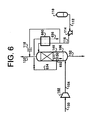
- FIG. 6 illustrates another embodiment of the invention which uses a distillation column 140 with a subcooler 600.
- Cryogenic liquid stream 634 a portion of the first oxygen-enriched liquid stream 130 produced in the distillation zone of the distillation column 140, is reduced in pressure and at least partially vaporized in the subcooler 600 to produce stream 636.
- a different cryogenic fluid also can be used as cooling utility.
- Nitrogen-rich liquid stream 116 is subcooled in the subcooler by indirect heat exchange with stream 634 prior to being introduced into the distillation column 140.
- the type of subcooler used may include, but is not limited to, a shell-and-tube heat exchanger, a plate-and-fin heat exchanger, or a brazed core.
- FIG. 7 illustrates another embodiment of the invention having one of many possible power recovery options.
- Cryogenic liquid stream 734 a portion of the first oxygen-enriched liquid stream 130 produced in the distillation zone of the distillation column 140, is pumped to a higher pressure in a pump 736, vaporized and warmed in a second vaporizer 738, and expanded in an expander 740 to produce stream 742.
- Nitrogen-containing gas stream 104 is further compressed in a second compressor 706 to produce stream 708 which is eventually introduced to distillation column 140.
- Pump 736 is optional.
- the type of vaporizer used may include, but is not limited to, an ambient or water bath vaporizer. Another source of heat may be employed to further preheat the feed to the expander 740.
- Power from the expander may be at least partially recovered in a generator (not shown). If a generator is used, then the second compressor 706 becomes optional. Expander 740 may directly or indirectly drive the second compressor 706, supplying at least a portion of the power for the second compressor.
- the second compressor 706 may also be used upstream of compressor 102 or in any other compression service, such as compressing cold or warm nitrogen-enriched vapour product stream 120. Recovered power also can be used to drive pumps. Power may be generated by vaporizing and expanding any cryogenic liquid within the process.
- the nitrogen-containing gas steam 100 can come from any source, which may include, but is not limited to, atmospheric air, a customer's compressed air system, a customer's compressed dry air system, or compressed air bottles.
- Stream 100 may be a nitrogen-containing stream having a different composition than atmospheric air.
- the nitrogen-rich liquid stream 112 can come from any source, which may include, but is not limited to, a liquid tanker trailer. Pump 114 is not needed if the nitrogen-rich liquid stream is at sufficient pressure to be introduced into the distillation column 140.
- the distillation column 140 may be an addition to an existing liquid nitrogen vaporization system.
- the nitrogen-enriched vapour product may be supplied cold, or it may be warmed to a desired temperature in another device not shown in the figures.
- the nitrogen-enriched vapour product may be further compressed or expanded.
- the compressed nitrogen-containing gas stream 104 may go through a prepurifier 408, such as shown in Figure 4, prior to being introduced to a vessel 308, such as shown in Figure 3.
- a vessel 308 such as shown in Figure 3.
- Any other product originating in the cryogenic distillation column, such as oxygen-enriched liquid, can be utilized in another process or device instead of being discarded. For example, it can be shipped to an air separation unit.
- Table 1 contains a numerical example corresponding to the embodiment of the invention shown in Figure 1.
- Stream No. Unit Value GAN requirement 120 SCFH (SCMH) 100 (2.83)
- the example shows that, at the above conditions, the process of the present invention saves approximately 29% of nitrogen-rich liquid that otherwise would have to be vaporized to generate the required product.
Landscapes
- Engineering & Computer Science (AREA)
- Physics & Mathematics (AREA)
- Mechanical Engineering (AREA)
- Thermal Sciences (AREA)
- General Engineering & Computer Science (AREA)
- Separation By Low-Temperature Treatments (AREA)
- Separation Using Semi-Permeable Membranes (AREA)
Abstract
Description
- The present invention relates generally to processes for the cryogenic production of a nitrogen-enriched vapour product from a supply of a nitrogen-rich liquid and a stream of a gas containing nitrogen and at least one contaminant ("contaminated nitrogen-containing gas") and has particular application to the cryogenic distillation of air.
- Nitrogen is one of the most important industrial gases. A common way to supply nitrogen to a process or a customer is a customer station. Typically, liquid nitrogen is hauled in a tanker from a cryogenic air separation plant or a liquefier to the customer's site, stored in a tank, optionally pumped to a desired pressure, and vaporized in an ambient vaporizer. This process is thermodynamically very inefficient. However, the equipment is inexpensive and reliable.
- Another common process to produce nitrogen on a customer's site is a cryogenic air separation unit. Air is purified to remove water, CO2, N2O, and other contaminants that may freeze in a cryogenic distillation column, cooled in a heat exchanger to close to its cryogenic saturation temperature (a temperature at which it starts liquefying after the bulk of contaminants is removed), and separated in a cryogenic distillation column into a nitrogen product and an oxygen-rich product. Cooling takes place against returning product streams. This process is thermodynamically very efficient but the equipment is expensive. Refrigeration is supplied by isentropic expansion of one of the streams in a turbine, or, as a less expensive alternative, by liquid nitrogen injection. Liquid nitrogen injection requires hauling liquid nitrogen to the site and storing the liquid nitrogen in a tank. A customer station is usually required as a backup system.
- "Cryogenic saturation" refers to the state of a gas when, if cooled, a portion of the gas is converted to a liquid. This liquid comprises the major components contained in the cryogenically saturated gas. This is different than ambient saturation, in which the resultant liquid comprises the minor components and/or impurities contained in the vapour.
- A "cryogen" refers to a liquid that normally exists at "cryogenic temperatures," which are defined as temperatures below -110°F (-79°C).
- US-B-6,202,422 (Brugerolle) discloses an air separation unit integrated with a gas turbine. This patent discloses a nitrogen wash column wherein liquid nitrogen is pumped to the top of the column and air from a gas turbine compressor is purified to remove water, CO2, and other contaminants that may freeze in a cryogenic distillation column. The purified air is cooled to a temperature close to its cryogenic saturation temperature, and is then introduced to the bottom of the column. Air from the gas turbine compressor is at a relatively high pressure, which reduces purification equipment cost. Gaseous nitrogen product is recovered from the top of the column, warmed against a feed air stream, and subsequently used in the gas turbine.
- US-B-6,276,171 (Brugerolle) and WO-A-00/60294 (Brugerolle) disclose a nitrogen wash column integrated with an air separation unit. Air to the column may come from a separate compressor. The air is purified by removing water, CO2 and other contaminants that may freeze in a cryogenic distillation column, and the purified air is cooled against a nitrogen product in a separate heat exchanger. The purposes of the system and process are: 1) to increase oxygen and nitrogen production of the air separation unit, and 2) to be able to operate the air separation unit and the nitrogen wash column independently of one another. For example, when the air separation unit is down, liquid nitrogen to the nitrogen wash column comes from a tank. Oxygen-rich liquid can be stored in another tank and returned to the air separation unit when it is back on line. Separate heat exchangers, compressors, and air purifiers help accomplish this task. This process is a variation of the thermodynamically efficient cryogenic air separation process discussed previously.
- There are many methods commonly used in the industry to purify air fed to an air separation unit such as a nitrogen wash column. One is a molecular sieve or activated alumina adsorber unit, which adsorbs water, CO2, N2O, and other contaminants that may freeze in the heat exchanger. It requires a low-pressure gas stream for regeneration. Another method is a reversing heat exchanger or a regenerator. Contaminants freeze out in a heat exchanger that cools incoming air from close-to-ambient temperature to close-to-cryogenic saturation temperature by exchanging heat with cryogenic vapour product or products. One unit is on stream while another is being regenerated. An adsorber unit with or without a heat exchanger, or a reversing heat exchanger, is expensive.
- It is desired to have an improved process for the production of a nitrogen-enriched vapour product.
- It is further desired to have a more efficient process for the production of a nitrogen-enriched vapour product.
- It is still further desired to have a more efficient and improved process for the production of a nitrogen-enriched vapour product which overcomes the difficulties and disadvantages of the prior art processes to provide better and more advantageous results.
- The invention is a process and a system for producing a nitrogen-enriched vapour product from a supply of a nitrogen-rich liquid. There are several variations of the process and several variations of the system.
- The process comprises feeding at least a portion of the supply of the nitrogen-rich liquid to a distillation zone at a first location; feeding a stream of a gas containing nitrogen and at least one contaminant ("contaminated nitrogen-containing gas") to a purifying device, wherein the gas is cooled by a cryogenic liquid whereby at least a portion of the at least one contaminant condenses, solidifies, or dissolves. At least a portion of, or derived from, the cool gas from the purifying device is fed to the distillation zone at a second location below the first location; a stream of the nitrogen-enriched vapour product is withdrawn from the distillation zone and a stream of a nitrogen-depleted liquid, which is an oxygen-enriched liquid when the contaminated nitrogen-containing gas is air or other oxygen-containing gas, is withdrawn from the distillation zone.
- At least a portion of the cryogenic liquid can be provided by at least a portion of the stream of the nitrogen-depleted liquid. The purifying device can be located inside or outside a distillation column comprising the distillation zone. The contaminated nitrogen-containing gas usually is air but can have a composition different than a composition of atmospheric air.
- The system for producing a nitrogen-enriched vapour product from a supply of a nitrogen-rich liquid comprises: a distillation column having a distillation zone; a purifying device in fluid communication with the distillation zone; a nitrogen-rich feed means for feeding at least a portion of the nitrogen-rich liquid to the distillation zone at a first location; a contaminated nitrogen-containing feed means for feeding a stream of the supply of a gas containing nitrogen and at least one contaminant to the purifying device; a cryogenic liquid feed means for feeding a stream of cryogenic liquid to the purifying device whereby the gas is cooled by the cryogenic liquid and at least a portion of the at least one contaminant condenses, solidifies, or dissolves; a nitrogen-enriched vapour withdrawal means for withdrawing a stream of the nitrogen-enriched vapour product from the distillation zone; a nitrogen-depleted liquid withdrawal means for withdrawing a stream of a nitrogen-depleted liquid from the distillation zone.
- At least a portion of the cryogenic liquid can be provided by at least a portion of the stream of the nitrogen-depleted liquid. The purifying device is located inside or outside the distillation column.
- The following is a description by way of example only, and with reference to the accompanying drawings of presently preferred embodiments of the invention. In the drawings:
- Figure 1 is a schematic diagram of one embodiment of the present invention;
- Figure 2 is a schematic diagram of a second embodiment of the present invention;
- Figure 3 is a schematic diagram of a third embodiment of the present invention;
- Figure 4 is a schematic diagram of a fourth embodiment of the present invention;
- Figure 5 is a schematic diagram of a fifth embodiment of the present invention;
- Figure 6 is a schematic diagram of a sixth embodiment of the present invention; and
- Figure 7 is a schematic diagram of a seventh embodiment of the present invention.
-
- Referring to Figure 1, a nitrogen-containing
gas stream 100, which also contains oxygen, is compressed incompressor 102. The resultingcompressed stream 104 may be cooled in an aftercooler or a chiller (not shown). Any condensate present at this point can be removed in a phase separator (not shown).Stream 104 is then fed to the bottom of acryogenic distillation column 140 wherestream 104 comes into direct contact with a first oxygen-enrichedliquid stream 130 from the distillation zone of the distillation column and vaporizes a portion of the oxygen-enriched liquid. Any contaminants present instream 104 are at least partially condensed, solidified, or dissolved in a purifyingdevice 106, which has components that may include, but are not limited to, trays, structured packing, random packing, vapour spargers, spray nozzles, screens, strainers, filters, or demisters, employed individually or in combination. The purifying device may also improve heat and/or mass transfer at the bottom of the distillation column and may perform part of the distillation separation. A nitrogen-richliquid stream 112 withdrawn from astorage tank 110 is pumped to a higher pressure in apump 114 before being introduced to the top of thedistillation column 140 asstream 116. Nitrogen-enrichedvapour product stream 120 is withdrawn from the top of the distillation column. A second oxygen-enriched liquid is withdrawn from the bottom of the distillation column and is discarded asstream 132, which contains at least a portion of any contaminants present in the nitrogen-containinggas stream 104. These contaminants may include, but are not limited to, water, CO2, N2O, and hydrocarbons. - Primary contact devices that perform distillation in the distillation zone of the
distillation column 140 may include, but are not limited to, structured packing, random packing, distillation trays, liquid spray in direct contact with vapour, or a combination of such devices. - When the
distillation column 140 is not in operation, thepurifying device 106 and the rest of the distillation column can be cleaned or defrosted by blowing through the distillation column nitrogen-containing gas from thecompressor 102. Bypassing the compressor aftercooler (not shown) may be used to control the temperature of the nitrogen-containinggas stream 104. - An
optional vaporizer 118 may be used to directly vaporize at least a portion of the nitrogen-richliquid stream 112 to produce at least a portion of the gaseous product in the nitrogen-enrichedvapour stream 120. The vaporizer also may be used when thedistillation column 140 is not in operation or to supplement the distillation column product. The vaporizer type may include, but is not limited to, an ambient or water bath vaporizer. - Figure 2 illustrates another embodiment of the invention. For simplicity, the unchanged equipment and stream numbers from Figure 1 have been retained in Figure 2. Compressed nitrogen-containing
gas stream 104 comes into contact with the first oxygen-enrichedliquid stream 130 from thedistillation column 140 in avessel 208 that contains thepurifying device 106. The resultingpurified vapour stream 210 is fed to the distillation column.Stream 210 is colder thanstream 104. Ideally,stream 210 is at its cryogenic saturation temperature. The second oxygen-enriched liquid is discarded instream 132, which contains at least a portion of any contaminants.Stream 130 may be pumped if necessary. - Contaminants collecting in the
vessel 208 or on the components of thepurifying device 106 can be removed either continuously or periodically. This may be done by taking the unit off line and blowing it clean with nitrogen-containing gas from thecompressor 102 or with another gas, or by other means. Two switching vessels may be employed. Also,vessel 208 may be placed inside thedistillation column 140, preferably under the distillation zone. - Figure 3 shows another embodiment of the invention. Compressed nitrogen-containing
gas stream 104 is cooled in thepurifying device 106 within avessel 308 by indirect heat exchange withstream 334, which is a portion of the first oxygen-enrichedliquid stream 130. Any contaminants instream 104 are at least partially condensed or solidified. The resulting purifiedstream 310 is fed to thedistillation column 140. Another portion ofstream 130,stream 332, is discarded.Stream 334 is at least partially vaporized and returned back to thedistillation column 140 asstream 336. Ifstream 334 is only partially vaporized, then theliquid portion 390 may also be discarded while the vapour portion is returned to the distillation column. It also is possible to put theentire stream 130 through thepurifying device 106 and then discard the liquid portion and return the vapour portion to the distillation column. This may require the use of a phase separator or a standpipe (not shown). - As an alternative, the cooling
utility stream 334 may not be a portion ofstream 130, but another cryogenic fluid, for example, at least a portion of the nitrogen-richliquid stream 116. Resulting nitrogen-rich vapour can be combined with the nitrogen-enrichedvapour product stream 120. - As shown in Figure 3, the
purifying device 106 is contained within thevessel 308. The heat transfer surface of the purifying device can be a simple or concentric coil, or a more complex heat exchanger. It also could be a device known in the industry as a vapour recovery system. Other components of the purifying device may include, but are not limited to, screens, strainers, filters, or demisters, employed individually or in combination. Contaminants collecting in thevessel 308 or on the components of thepurifying device 106 can be removed either continuously or periodically. This may be done by taking the unit off line and blowing it clean with nitrogen-containing gas from thecompressor 102 or with another gas, or by other means. Two switching purifiers may be employed. Also,vessel 308 may be placed inside thedistillation column 140, preferably under the distillation zone of the distillation column. - Figure 4 illustrates another embodiment of the invention. The compressed nitrogen-containing
gas stream 104 goes through aprepurifier 408 prior to being introduced to thedistribution column 140 asstream 410. Typically, theprepurifier 408 can be used to remove instream 490 the bulk of the water that may be present instream 104. The prepurifier also may be used to enrichstream 104 in nitrogen by rejecting a portion of the oxygen in the nitrogen-containing gas. In fact, the prepurifier could be used for both water removal and nitrogen enrichment. In such situation, multiple prepurifiers can be used. Although other contaminants, such as carbon dioxide (CO2), nitrous oxide (N2O) and hydrocarbons are typically removed in thepurifying device 106, which may be placed inside or outside of thedistillation column 140 and be of any the types previously described, one of ordinary skill in the art will recognize that a prepurifier can be used to remove/reject a portion of any impurity (i.e., water, CO2, N2O or hydrocarbons), with or without simultaneously enriching the feed in nitrogen (rejection of oxygen). The purifying device then can remove any remaining contaminants to acceptable levels. The prepurifier type used may include, but is not limited to, a membrane separation unit or an adsorption unit. The membrane separation unit can be envisaged to be a single membrane or a complex unit containing a number of membranes of the same type or different types arranged in series or in parallel. It can remove/reject at least a portion of one component (i.e., water, oxygen) or at least a portion of a number of components. - Figure 5 illustrates another embodiment of the invention which uses a
distillation column 140 with a condenser. Cryogenicliquid stream 534, a portion of the first oxygen-enrichedliquid stream 130 produced in the distillation zone of thedistillation column 140, is reduced in pressure and at least partially vaporized against condensing vapour from the top of the distillation zone to produce stream 536. A different cryogenic fluid also can be used as cooling utility. Condensation can take place inside of the distillation column or in a separate vessel. Condensate is returned back to the distillation column or to a storage vessel such asstorage tank 110. - The type of condenser used may include, but is not limited to, a shell-and-tube heat exchanger, a plate-and-fin heat exchanger, a brazed core, or a simple device similar to those used to recondense vapours in a tank. It could be a single or concentric coil, or a finned tube.
- Figure 6 illustrates another embodiment of the invention which uses a
distillation column 140 with asubcooler 600. Cryogenicliquid stream 634, a portion of the first oxygen-enrichedliquid stream 130 produced in the distillation zone of thedistillation column 140, is reduced in pressure and at least partially vaporized in thesubcooler 600 to producestream 636. A different cryogenic fluid also can be used as cooling utility. Nitrogen-richliquid stream 116 is subcooled in the subcooler by indirect heat exchange withstream 634 prior to being introduced into thedistillation column 140. The type of subcooler used may include, but is not limited to, a shell-and-tube heat exchanger, a plate-and-fin heat exchanger, or a brazed core. - Figure 7 illustrates another embodiment of the invention having one of many possible power recovery options. Cryogenic
liquid stream 734, a portion of the first oxygen-enrichedliquid stream 130 produced in the distillation zone of thedistillation column 140, is pumped to a higher pressure in a pump 736, vaporized and warmed in asecond vaporizer 738, and expanded in anexpander 740 to producestream 742. Nitrogen-containinggas stream 104 is further compressed in asecond compressor 706 to producestream 708 which is eventually introduced todistillation column 140. Pump 736 is optional. The type of vaporizer used may include, but is not limited to, an ambient or water bath vaporizer. Another source of heat may be employed to further preheat the feed to theexpander 740. Power from the expander may be at least partially recovered in a generator (not shown). If a generator is used, then thesecond compressor 706 becomes optional.Expander 740 may directly or indirectly drive thesecond compressor 706, supplying at least a portion of the power for the second compressor. - The
second compressor 706 may also be used upstream ofcompressor 102 or in any other compression service, such as compressing cold or warm nitrogen-enrichedvapour product stream 120. Recovered power also can be used to drive pumps. Power may be generated by vaporizing and expanding any cryogenic liquid within the process. - The comments below apply to all of the embodiments which are discussed above and illustrated in Figures 1-7.
- The nitrogen-containing
gas steam 100 can come from any source, which may include, but is not limited to, atmospheric air, a customer's compressed air system, a customer's compressed dry air system, or compressed air bottles.Stream 100 may be a nitrogen-containing stream having a different composition than atmospheric air. Similarly, the nitrogen-richliquid stream 112 can come from any source, which may include, but is not limited to, a liquid tanker trailer.Pump 114 is not needed if the nitrogen-rich liquid stream is at sufficient pressure to be introduced into thedistillation column 140. - The
distillation column 140 may be an addition to an existing liquid nitrogen vaporization system. - The nitrogen-enriched vapour product may be supplied cold, or it may be warmed to a desired temperature in another device not shown in the figures. The nitrogen-enriched vapour product may be further compressed or expanded.
- In general, there is no need to exchange heat between the nitrogen-enriched vapour product and the nitrogen-containing gas. However, cold or partially warmed nitrogen-enriched vapour product can be used to chill the nitrogen-containing gas to some temperature at which the contaminants would not freeze out. If the bulk of water is removed, as shown in Figure 4, a colder temperature can be achieved.
- Any combination of devices described above can be used. For example, the compressed nitrogen-containing
gas stream 104 may go through aprepurifier 408, such as shown in Figure 4, prior to being introduced to avessel 308, such as shown in Figure 3. Any other product originating in the cryogenic distillation column, such as oxygen-enriched liquid, can be utilized in another process or device instead of being discarded. For example, it can be shipped to an air separation unit. - Table 1 contains a numerical example corresponding to the embodiment of the invention shown in Figure 1.
Stream No. Unit Value GAN requirement 120 SCFH (SCMH) 100 (2.83) GAN pressure 120 psia (kPa) 80 (550) GAN purity 120 ppm O2 1 LIN required 116 SCFH (SCMH) 71 (2.01) AIR required 100 SCFH (SCMH) 43 (1.22) LIN savings SCFH (SCMH) 29 (0.82) - The example shows that, at the above conditions, the process of the present invention saves approximately 29% of nitrogen-rich liquid that otherwise would have to be vaporized to generate the required product.
- Although illustrated and described herein with reference to certain specific embodiments, the present invention is nevertheless not intended to be limited to the details shown. Rather, various modifications may be made in the details within the scope of the claims.
Claims (28)
- A process for producing a nitrogen-enriched vapour product from a supply of a nitrogen-rich liquid, said process comprising:feeding at least a portion of the nitrogen-rich liquid to a distillation zone at a first location;feeding a stream of a gas containing nitrogen and at least one contaminant ("contaminated nitrogen-containing gas") to a purifying device, wherein the gas is cooled by a cryogenic liquid whereby at least a portion of the at least one contaminant condenses, solidifies, or dissolves;feeding at least a portion of, or derived from, the cooled gas from the purifying device to the distillation zone at a second location below the first location;withdrawing a stream of the nitrogen-enriched vapour product from the distillation zone; andwithdrawing a stream of a nitrogen-depleted liquid from the distillation zone.
- A process as claimed in Claim 1, wherein at least a portion of the cryogenic liquid is at least a portion of the stream of the nitrogen-depleted liquid.
- A process as claimed in Claim 1 or Claim 2, wherein at least a portion of the cryogenic liquid is a portion of the nitrogen-rich liquid.
- A process as claimed in any one of the preceding claims, wherein the contaminated nitrogen-containing gas is cooled in the purifying device by direct contact with the cryogenic liquid.
- A process as claimed in any one of Claims 1 to 3, wherein the contaminated nitrogen-containing gas is cooled in the purification device by indirect heat exchange with the cryogenic liquid.
- A process as claimed in any one of the preceding claims, wherein the purifying device is located inside a distillation column containing said distillation zone.
- A process as claimed in Claim 6, wherein the purifying device improves the heat and/or mass transfer at the bottom of the distillation column.
- A process as claimed in any one of Claims 1 to 5, wherein the purifying device is located outside a distillation column containing said distillation zone.
- A process as claimed in any one of the preceding claims, wherein another portion of the nitrogen-rich liquid is vaporized to supplement the nitrogen-enriched vapour product from the distillation zone.
- A process as claimed in any one of the preceding claims, wherein the contaminated nitrogen-containing gas is compressed air.
- A process as in any one of Claims 1 to 9, wherein the contaminated nitrogen-containing gas is an oxygen-containing gas having a composition different than a composition of atmospheric air.
- A process as claimed in any one of the preceding claims, wherein the contaminant is water, carbon dioxide, nitrous oxide, hydrocarbons or mixtures thereof.
- A process as claimed in any one of the preceding claims, wherein the contaminated nitrogen-containing gas is fed to a prepurifier to remove at least a portion of the contaminant prior to being fed to the purifying device.
- A process as claimed in any one of the preceding claims, wherein the contaminated nitrogen-containing gas is fed to a prepurifier to enrich the feed in nitrogen prior to being fed to the purifying device.
- A system for producing a nitrogen-enriched vapour product from a supply of a nitrogen-rich liquid by a process as defined in Claim 1, comprising:a distillation column (140) having a distillation zone;a purifying device (106) in fluid communication with the distillation zone;a nitrogen-rich liquid feed means (112, 114, 116) for feeding at least a portion of the nitrogen-rich liquid to the distillation zone at a first location;a contaminated nitrogen-containing feed means (100, 102, 104) for feeding a stream of a gas containing nitrogen and at least one contaminant to the purifying device,a cryogenic liquid feed means (130; 130, 334) for feeding a stream of cryogenic liquid to the purifying means whereby the gas is cooled by the cryogenic liquid and at least a portion of the at least one contaminant condenses, solidifies, or dissolves;a nitrogen-enriched vapour withdrawal means (120) for withdrawing a stream of the nitrogen-enriched vapour product from the distillation zone; anda nitrogen-depleted liquid withdrawal means (130) for withdrawing a stream of a nitrogen-depleted liquid from the distillation zone.
- A system as claimed in Claim 15, wherein said cryogenic liquid feed means (130; 130, 334) is in fluid communication with said nitrogen-depleted liquid withdrawal means (130) whereby at least a portion of the cryogenic liquid is at least a portion of the stream of the nitrogen-depleted liquid.
- A system as claimed in Claim 15 or Claim 16, wherein the contaminated nitrogen-containing gas directly contacts the cryogenic liquid in the purifying device (106).
- A system as claimed in Claim 15 or Claim 16, wherein the contaminated nitrogen-containing gas stream is in indirect heat exchange with the cryogenic liquid in the purifying device (106).
- A system as claimed in any one of Claims 15 to 18, wherein the purifying device (106) is located inside the distillation column (140).
- A system as claimed in Claim 19, wherein the purifying device improves the heat and/or mass transfer at the bottom of the distillation column.
- A system as claimed in any one of Claims 15 to 18, wherein the purifying device (106) is located outside the distillation column (140).
- A system as claimed in any one of Claims 15 to 21, wherein the purifying device comprises trays, structured packing, random packing, vapour spargers, spray nozzles, screens, strainers, filters, or demisters, employed individually or in combination.
- A system as claimed in any one of Claims 15 to 22, further comprising vaporizing means (118) to vaporize another portion of the nitrogen-rich liquid.
- A system as claimed in any one of Claims 15 to 23, wherein said contaminated nitrogen-containing feed means comprises an ambient air inlet (100) and an air compressor (102).
- A system as claimed in any one of Claims 15 to 24, wherein said contaminated nitrogen-containing feed means comprises a prepurifying device (408. 409) in fluid communication with the purifying device (106) and a prepurified gas from said prepurifying device (408, 409) is fed to said purifying device (106).
- A system as claimed in Claim 25, wherein the prepurifying device (408, 409) is a membrane separation device consisting at least one membrane.
- A system as claimed in Claim 26, wherein the membrane separation device (408.409) is for the removal of water, carbon dioxide, nitrous oxide, hydrocarbons or mixtures thereof from the contaminated nitrogen-containing gas stream.
- A system as claimed in Claim 26 or Claim 27, wherein the membrane separation device (408, 409) is used for the rejection of at least a portion of an oxygen-containing contaminated nitrogen-containing from gas stream thereby enriching the prepurified gas in nitrogen.
Applications Claiming Priority (4)
| Application Number | Priority Date | Filing Date | Title |
|---|---|---|---|
| US10/136,999 US6487877B1 (en) | 2002-05-01 | 2002-05-01 | Nitrogen generation process |
| US136999 | 2002-05-01 | ||
| US290561 | 2002-11-08 | ||
| US10/290,561 US6637240B1 (en) | 2002-05-01 | 2002-11-08 | Nitrogen generation process |
Publications (1)
| Publication Number | Publication Date |
|---|---|
| EP1363093A1 true EP1363093A1 (en) | 2003-11-19 |
Family
ID=22475370
Family Applications (1)
| Application Number | Title | Priority Date | Filing Date |
|---|---|---|---|
| EP03252634A Withdrawn EP1363093A1 (en) | 2002-05-01 | 2003-04-25 | Nitrogen generation process |
Country Status (4)
| Country | Link |
|---|---|
| US (2) | US6487877B1 (en) |
| EP (1) | EP1363093A1 (en) |
| JP (1) | JP2004003836A (en) |
| CN (1) | CN1288410C (en) |
Families Citing this family (6)
| Publication number | Priority date | Publication date | Assignee | Title |
|---|---|---|---|---|
| US6487877B1 (en) * | 2002-05-01 | 2002-12-03 | Air Products And Chemicals, Inc. | Nitrogen generation process |
| JP4321095B2 (en) * | 2003-04-09 | 2009-08-26 | 日立アプライアンス株式会社 | Refrigeration cycle equipment |
| US7081153B2 (en) * | 2003-12-02 | 2006-07-25 | Honeywell International Inc. | Gas generating system and method for inerting aircraft fuel tanks |
| US7272954B2 (en) * | 2004-07-14 | 2007-09-25 | L'air Liquide, Societe Anonyme A Directoire Et Conseil De Surveillance Pour L'etude Et L'exploitation Des Proceded Georges Claude | Low temperature air separation process for producing pressurized gaseous product |
| CN103080678B (en) * | 2010-09-09 | 2015-08-12 | 乔治洛德方法研究和开发液化空气有限公司 | Method and apparatus for separating air by cryogenic distillation |
| FR2977303B1 (en) * | 2011-06-29 | 2018-03-02 | L'air Liquide, Societe Anonyme Pour L'etude Et L'exploitation Des Procedes Georges Claude | PROCESS AND APPARATUS FOR NITROGEN PRODUCTION BY CRYOGENIC DISTILLATION |
Citations (5)
| Publication number | Priority date | Publication date | Assignee | Title |
|---|---|---|---|---|
| US3109726A (en) * | 1957-07-31 | 1963-11-05 | Linde Eismasch Ag | Process for removing solid carbon dioxide from air during its rectification |
| US3440827A (en) * | 1965-07-07 | 1969-04-29 | Conch Int Methane Ltd | Air drying by direct contact with separated liquid oxygen fraction |
| US5743112A (en) * | 1995-11-02 | 1998-04-28 | Teisan Kabushiki Kaisha | Ultra high purity nitrogen and oxygen generator unit |
| WO2000060294A1 (en) * | 1999-04-05 | 2000-10-12 | L'air Liquide Societe Anonyme Pour L'etude Et L'exploitation Des Procedes Georges Claude | Variable capacity fluid mixture separation apparatus and process |
| EP1271081A2 (en) * | 2001-06-12 | 2003-01-02 | Air Products And Chemicals, Inc. | Air seperation process |
Family Cites Families (8)
| Publication number | Priority date | Publication date | Assignee | Title |
|---|---|---|---|---|
| US3363427A (en) * | 1964-06-02 | 1968-01-16 | Air Reduction | Production of ultrahigh purity oxygen with removal of hydrocarbon impurities |
| US3739593A (en) * | 1968-12-04 | 1973-06-19 | Trane Co | Gas separation system |
| US4038060A (en) * | 1972-12-01 | 1977-07-26 | Hitachi, Ltd. | Apparatus for treating an exhaust gas from nuclear plant |
| US5049174A (en) * | 1990-06-18 | 1991-09-17 | Air Products And Chemicals, Inc. | Hybrid membrane - cryogenic generation of argon concurrently with nitrogen |
| US5711166A (en) | 1997-01-22 | 1998-01-27 | The Boc Group, Inc. | Air separation method and apparatus |
| US6276171B1 (en) | 1999-04-05 | 2001-08-21 | L'air Liquide, Societe Anonyme Pour L'etude Et L'exploitation Des Procedes Georges Claude | Integrated apparatus for generating power and/or oxygen enriched fluid, process for the operation thereof |
| US6202442B1 (en) | 1999-04-05 | 2001-03-20 | L'air Liquide, Societe Anonyme Pour L'etude Et L'expoitation Des Procedes Georges Claude | Integrated apparatus for generating power and/or oxygen enriched fluid and process for the operation thereof |
| US6487877B1 (en) * | 2002-05-01 | 2002-12-03 | Air Products And Chemicals, Inc. | Nitrogen generation process |
-
2002
- 2002-05-01 US US10/136,999 patent/US6487877B1/en not_active Expired - Fee Related
- 2002-11-08 US US10/290,561 patent/US6637240B1/en not_active Expired - Fee Related
-
2003
- 2003-04-25 EP EP03252634A patent/EP1363093A1/en not_active Withdrawn
- 2003-04-29 CN CNB031284353A patent/CN1288410C/en not_active Expired - Fee Related
- 2003-05-01 JP JP2003126466A patent/JP2004003836A/en active Pending
Patent Citations (5)
| Publication number | Priority date | Publication date | Assignee | Title |
|---|---|---|---|---|
| US3109726A (en) * | 1957-07-31 | 1963-11-05 | Linde Eismasch Ag | Process for removing solid carbon dioxide from air during its rectification |
| US3440827A (en) * | 1965-07-07 | 1969-04-29 | Conch Int Methane Ltd | Air drying by direct contact with separated liquid oxygen fraction |
| US5743112A (en) * | 1995-11-02 | 1998-04-28 | Teisan Kabushiki Kaisha | Ultra high purity nitrogen and oxygen generator unit |
| WO2000060294A1 (en) * | 1999-04-05 | 2000-10-12 | L'air Liquide Societe Anonyme Pour L'etude Et L'exploitation Des Procedes Georges Claude | Variable capacity fluid mixture separation apparatus and process |
| EP1271081A2 (en) * | 2001-06-12 | 2003-01-02 | Air Products And Chemicals, Inc. | Air seperation process |
Also Published As
| Publication number | Publication date |
|---|---|
| JP2004003836A (en) | 2004-01-08 |
| CN1455216A (en) | 2003-11-12 |
| CN1288410C (en) | 2006-12-06 |
| US6487877B1 (en) | 2002-12-03 |
| US6637240B1 (en) | 2003-10-28 |
Similar Documents
| Publication | Publication Date | Title |
|---|---|---|
| AU708298B2 (en) | Air separation method and apparatus | |
| JP4450886B2 (en) | High purity oxygen production method and apparatus | |
| EP0194795B1 (en) | Purification of carbon dioxide for use in brewing | |
| EP0412793A1 (en) | Process and apparatus for producing nitrogen from air | |
| KR20030036029A (en) | Process and apparatus for producing krypton and/or xenon by low-temperature fractionation of air | |
| JP4728219B2 (en) | Method and system for producing pressurized air gas by cryogenic distillation of air | |
| JPH0579753A (en) | Method and device to manufacture gas-state oxygen under pressure | |
| US4883519A (en) | Process for the production of high pressure nitrogen with split reboil-condensing duty | |
| JPH06207775A (en) | Low-temperature air separating method for manufacturing nitrogen having no carbon monoxide | |
| US5049174A (en) | Hybrid membrane - cryogenic generation of argon concurrently with nitrogen | |
| KR0158730B1 (en) | Pumped liquid oxygen method and apparatus | |
| KR20130032382A (en) | High pressure recovery of carbon dioxide from a fermentation process | |
| US6637240B1 (en) | Nitrogen generation process | |
| AU3336899A (en) | Method and installation for air distillation with production of argon | |
| US6708523B2 (en) | Process and apparatus for producing high-purity nitrogen by low-temperature fractionation of air | |
| EP0756144B1 (en) | High purity nitrogen gas generator | |
| EP2447653A1 (en) | Process for cryogenic air separation using a side condenser | |
| EP1207362A1 (en) | Process and apparatus for the production of low pressure gaseous oxygen | |
| JP4206083B2 (en) | Argon production method using cryogenic air separator | |
| US6070432A (en) | Production of cryogenic liquid mixtures | |
| CN113701451B (en) | Method and apparatus for separating air by low-temperature distillation | |
| EP0855565A2 (en) | Air separation method and apparatus | |
| US5419137A (en) | Air separation process and apparatus for the production of high purity nitrogen | |
| AU2016218602B2 (en) | Method for recovering helium | |
| JP2000180051A (en) | Manufacture of ultrahigh purity nitrogen |
Legal Events
| Date | Code | Title | Description |
|---|---|---|---|
| PUAI | Public reference made under article 153(3) epc to a published international application that has entered the european phase |
Free format text: ORIGINAL CODE: 0009012 |
|
| AK | Designated contracting states |
Kind code of ref document: A1 Designated state(s): AT BE BG CH CY CZ DE DK EE ES FI FR GB GR HU IE IT LI LU MC NL PT RO SE SI SK TR |
|
| AX | Request for extension of the european patent |
Extension state: AL LT LV MK |
|
| 17P | Request for examination filed |
Effective date: 20031103 |
|
| AKX | Designation fees paid |
Designated state(s): AT BE BG CH CY CZ DE DK EE ES FI FR GB GR HU IE IT LI LU MC NL PT RO SE SI SK TR |
|
| STAA | Information on the status of an ep patent application or granted ep patent |
Free format text: STATUS: THE APPLICATION IS DEEMED TO BE WITHDRAWN |
|
| 18D | Application deemed to be withdrawn |
Effective date: 20090318 |