EP1363077A2 - Gas turbine combustor and combustion control method thereof - Google Patents
Gas turbine combustor and combustion control method thereof Download PDFInfo
- Publication number
- EP1363077A2 EP1363077A2 EP03010794A EP03010794A EP1363077A2 EP 1363077 A2 EP1363077 A2 EP 1363077A2 EP 03010794 A EP03010794 A EP 03010794A EP 03010794 A EP03010794 A EP 03010794A EP 1363077 A2 EP1363077 A2 EP 1363077A2
- Authority
- EP
- European Patent Office
- Prior art keywords
- float
- bypass duct
- air
- gas turbine
- combustor
- Prior art date
- Legal status (The legal status is an assumption and is not a legal conclusion. Google has not performed a legal analysis and makes no representation as to the accuracy of the status listed.)
- Granted
Links
Images


Classifications
-
- F—MECHANICAL ENGINEERING; LIGHTING; HEATING; WEAPONS; BLASTING
- F23—COMBUSTION APPARATUS; COMBUSTION PROCESSES
- F23R—GENERATING COMBUSTION PRODUCTS OF HIGH PRESSURE OR HIGH VELOCITY, e.g. GAS-TURBINE COMBUSTION CHAMBERS
- F23R3/00—Continuous combustion chambers using liquid or gaseous fuel
- F23R3/02—Continuous combustion chambers using liquid or gaseous fuel characterised by the air-flow or gas-flow configuration
- F23R3/04—Air inlet arrangements
- F23R3/06—Arrangement of apertures along the flame tube
-
- F—MECHANICAL ENGINEERING; LIGHTING; HEATING; WEAPONS; BLASTING
- F23—COMBUSTION APPARATUS; COMBUSTION PROCESSES
- F23R—GENERATING COMBUSTION PRODUCTS OF HIGH PRESSURE OR HIGH VELOCITY, e.g. GAS-TURBINE COMBUSTION CHAMBERS
- F23R3/00—Continuous combustion chambers using liquid or gaseous fuel
- F23R3/02—Continuous combustion chambers using liquid or gaseous fuel characterised by the air-flow or gas-flow configuration
- F23R3/04—Air inlet arrangements
- F23R3/10—Air inlet arrangements for primary air
- F23R3/12—Air inlet arrangements for primary air inducing a vortex
- F23R3/14—Air inlet arrangements for primary air inducing a vortex by using swirl vanes
-
- F—MECHANICAL ENGINEERING; LIGHTING; HEATING; WEAPONS; BLASTING
- F23—COMBUSTION APPARATUS; COMBUSTION PROCESSES
- F23R—GENERATING COMBUSTION PRODUCTS OF HIGH PRESSURE OR HIGH VELOCITY, e.g. GAS-TURBINE COMBUSTION CHAMBERS
- F23R3/00—Continuous combustion chambers using liquid or gaseous fuel
- F23R3/02—Continuous combustion chambers using liquid or gaseous fuel characterised by the air-flow or gas-flow configuration
- F23R3/26—Controlling the air flow
-
- Y—GENERAL TAGGING OF NEW TECHNOLOGICAL DEVELOPMENTS; GENERAL TAGGING OF CROSS-SECTIONAL TECHNOLOGIES SPANNING OVER SEVERAL SECTIONS OF THE IPC; TECHNICAL SUBJECTS COVERED BY FORMER USPC CROSS-REFERENCE ART COLLECTIONS [XRACs] AND DIGESTS
- Y02—TECHNOLOGIES OR APPLICATIONS FOR MITIGATION OR ADAPTATION AGAINST CLIMATE CHANGE
- Y02T—CLIMATE CHANGE MITIGATION TECHNOLOGIES RELATED TO TRANSPORTATION
- Y02T50/00—Aeronautics or air transport
- Y02T50/60—Efficient propulsion technologies, e.g. for aircraft
Definitions
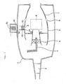
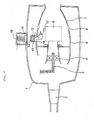
- control of the local fuel-air ratio is done such that the actuator 11 is operated to thereby operate the bypass duct variable valve 10 so as to control the air quantity to be supplied into the primary combustion zone 9 via the swirler 4.
- the combustor case 1 is usually heated to about 600°C and the liner 5 to about 900°C and hence sliding portions of the components of the air quantity control mechanism that operates in such high temperature portions are liable to cause sticking, biting, etc., which often leads to a large damage of reliability of the design of the device.
- Numeral 13 designates a float guide, that guides the movement of the float 12.
- the float guide 13 is formed in a cylindrical shape and, at each of upper and lower ends thereof, has a stopper 14 on which the float 12 abuts to stop. It is to be noted that the stopper 14 at the lower end of the float guide 13 is not necessarily provided by the float guide 13 but it may be provided by an inner periphery of a hole provided to form the bypass duct 8 in the wall of the liner 5.
Landscapes
- Engineering & Computer Science (AREA)
- Chemical & Material Sciences (AREA)
- Combustion & Propulsion (AREA)
- Mechanical Engineering (AREA)
- General Engineering & Computer Science (AREA)
Abstract
Description
Claims (3)
- A gas turbine combustor comprising a liner provided in a combustor case and a bypass duct provided in said liner and being constructed so as to enable a control of flow rate of air supplied into a primary combustion zone via a swirler by causing a portion of the air to pass through said bypass duct, characterized in further comprising a float, made of a magnetic substance, provided in said bypass duct so as to open and close said bypass duct by the position of movement of said float and an electromagnetic coil provided outside of said combustor case corresponding to the position of said float so as to move said float.
- A gas turbine combustor as claimed in Claim 1, characterized in further comprising a float guide guiding said float and a stopper, on which said float abuts, provided at a lower end of said float guide.
- A combustion control method of a gas turbine combustor as claimed in Claim 1 or 2, characterized in that the position of movement of said float is changed by said electromagnetic coil and the portion of the air is caused to pass through said bypass duct corresponding to the position of movement of said float, so that the flow rate of the air supplied into said primary combustion zone via said swirler is controlled and a local fuel-air ratio in said primary combustion zone is controlled.
Applications Claiming Priority (2)
| Application Number | Priority Date | Filing Date | Title |
|---|---|---|---|
| JP2002138348 | 2002-05-14 | ||
| JP2002138348A JP2003329244A (en) | 2002-05-14 | 2002-05-14 | Gas turbine combustor and combustion controlling method |
Publications (3)
| Publication Number | Publication Date |
|---|---|
| EP1363077A2 true EP1363077A2 (en) | 2003-11-19 |
| EP1363077A3 EP1363077A3 (en) | 2005-02-02 |
| EP1363077B1 EP1363077B1 (en) | 2008-04-16 |
Family
ID=29267770
Family Applications (1)
| Application Number | Title | Priority Date | Filing Date |
|---|---|---|---|
| EP03010794A Expired - Lifetime EP1363077B1 (en) | 2002-05-14 | 2003-05-14 | Gas turbine combustor and combustion control method thereof |
Country Status (4)
| Country | Link |
|---|---|
| US (1) | US6892543B2 (en) |
| EP (1) | EP1363077B1 (en) |
| JP (1) | JP2003329244A (en) |
| DE (1) | DE60320344T2 (en) |
Cited By (2)
| Publication number | Priority date | Publication date | Assignee | Title |
|---|---|---|---|---|
| EP2784393A1 (en) * | 2013-03-26 | 2014-10-01 | Siemens Aktiengesellschaft | Gas turbine combustion chamber with secondary air flaps |
| CN108458366A (en) * | 2018-01-23 | 2018-08-28 | 中科合肥微小型燃气轮机研究院有限责任公司 | A kind of bush assembly of adjustable combustion area air mass flow |
Families Citing this family (20)
| Publication number | Priority date | Publication date | Assignee | Title |
|---|---|---|---|---|
| US20070049981A1 (en) * | 2005-08-23 | 2007-03-01 | Rorvick Anthony W | Capacitor reformation method and device configured to perform the capacitor reformation method |
| US20070151257A1 (en) * | 2006-01-05 | 2007-07-05 | Maier Mark S | Method and apparatus for enabling engine turn down |
| US8915086B2 (en) * | 2006-08-07 | 2014-12-23 | General Electric Company | System for controlling combustion dynamics and method for operating the same |
| US7878002B2 (en) * | 2007-04-17 | 2011-02-01 | General Electric Company | Methods and systems to facilitate reducing combustor pressure drops |
| GB2455289B (en) * | 2007-12-03 | 2010-04-07 | Siemens Ag | Improvements in or relating to burners for a gas-turbine engine |
| US20090260340A1 (en) * | 2008-04-17 | 2009-10-22 | General Electric Company | Combustor of a Turbine, a Method of Retro-Fitting a Combustor of a Turbine and a Method of Building a Combustor of a Turbine |
| US8099941B2 (en) * | 2008-12-31 | 2012-01-24 | General Electric Company | Methods and systems for controlling a combustor in turbine engines |
| GB201200237D0 (en) * | 2012-01-09 | 2012-02-22 | Rolls Royce Plc | A combustor for a gas turbine engine |
| DE102012204022A1 (en) | 2012-03-14 | 2013-09-19 | Siemens Aktiengesellschaft | Gas turbine and method for its operation |
| US10480418B2 (en) | 2012-10-26 | 2019-11-19 | Powerphase Llc | Gas turbine energy supplementing systems and heating systems, and methods of making and using the same |
| KR102009583B1 (en) | 2012-10-26 | 2019-08-09 | 파워페이즈 엘엘씨 | Gas turbine energy supplementing systems and heating systems, and methods of making and using the same |
| KR102129052B1 (en) * | 2013-11-12 | 2020-07-02 | 한화에어로스페이스 주식회사 | Swirler assembly |
| US10337411B2 (en) | 2015-12-30 | 2019-07-02 | General Electric Company | Auto thermal valve (ATV) for dual mode passive cooling flow modulation |
| US20170191373A1 (en) | 2015-12-30 | 2017-07-06 | General Electric Company | Passive flow modulation of cooling flow into a cavity |
| US10337739B2 (en) | 2016-08-16 | 2019-07-02 | General Electric Company | Combustion bypass passive valve system for a gas turbine |
| US10712007B2 (en) | 2017-01-27 | 2020-07-14 | General Electric Company | Pneumatically-actuated fuel nozzle air flow modulator |
| US10738712B2 (en) | 2017-01-27 | 2020-08-11 | General Electric Company | Pneumatically-actuated bypass valve |
| US10830438B2 (en) | 2017-10-12 | 2020-11-10 | Raytheon Technologies Corporation | Modulated combustor bypass |
| US11060463B2 (en) * | 2018-01-08 | 2021-07-13 | Raytheon Technologies Corporation | Modulated combustor bypass and combustor bypass valve |
| DE102020116245B4 (en) | 2020-06-19 | 2024-03-07 | Man Energy Solutions Se | Gas turbine assembly with combustion chamber air bypass |
Family Cites Families (11)
| Publication number | Priority date | Publication date | Assignee | Title |
|---|---|---|---|---|
| US3899881A (en) * | 1974-02-04 | 1975-08-19 | Gen Motors Corp | Combustion apparatus with secondary air to vaporization chamber and concurrent variance of secondary air and dilution air in a reverse sense |
| US3958413A (en) * | 1974-09-03 | 1976-05-25 | General Motors Corporation | Combustion method and apparatus |
| JPS58140520A (en) * | 1982-02-16 | 1983-08-20 | Toshiba Corp | Combustion apparatus |
| JPS5952121A (en) * | 1983-08-02 | 1984-03-26 | Matsushita Electric Ind Co Ltd | Combustor air volume switching device |
| JPS61282682A (en) | 1985-05-20 | 1986-12-12 | Sanyo Electric Co Ltd | Feed air damper device of combustion apparatus |
| AT393890B (en) * | 1989-10-20 | 1991-12-27 | Vaillant Gmbh | DEVICE FOR CONTROLLING THE FLOW OF COMBUSTION AIR TO A FAN BURNER |
| DE69421896T2 (en) * | 1993-12-22 | 2000-05-31 | Siemens Westinghouse Power Corp., Orlando | Bypass valve for the combustion chamber of a gas turbine |
| US5924276A (en) * | 1996-07-17 | 1999-07-20 | Mowill; R. Jan | Premixer with dilution air bypass valve assembly |
| DE19645196B4 (en) * | 1996-11-02 | 2006-08-17 | J. Eberspächer GmbH & Co. KG | Liquid fuel heater |
| US6199364B1 (en) * | 1999-01-22 | 2001-03-13 | Alzeta Corporation | Burner and process for operating gas turbines with minimal NOx emissions |
| US6449956B1 (en) * | 2001-04-09 | 2002-09-17 | General Electric Company | Bypass air injection method and apparatus for gas turbines |
-
2002
- 2002-05-14 JP JP2002138348A patent/JP2003329244A/en not_active Withdrawn
-
2003
- 2003-05-13 US US10/436,272 patent/US6892543B2/en not_active Expired - Lifetime
- 2003-05-14 EP EP03010794A patent/EP1363077B1/en not_active Expired - Lifetime
- 2003-05-14 DE DE60320344T patent/DE60320344T2/en not_active Expired - Lifetime
Cited By (4)
| Publication number | Priority date | Publication date | Assignee | Title |
|---|---|---|---|---|
| EP2784393A1 (en) * | 2013-03-26 | 2014-10-01 | Siemens Aktiengesellschaft | Gas turbine combustion chamber with secondary air flaps |
| WO2014154401A1 (en) * | 2013-03-26 | 2014-10-02 | Siemens Aktiengesellschaft | Gas turbine combustion chamber having secondary air flaps |
| CN108458366A (en) * | 2018-01-23 | 2018-08-28 | 中科合肥微小型燃气轮机研究院有限责任公司 | A kind of bush assembly of adjustable combustion area air mass flow |
| CN108458366B (en) * | 2018-01-23 | 2020-06-19 | 中科合肥微小型燃气轮机研究院有限责任公司 | A liner assembly that regulates air flow in the combustion zone |
Also Published As
| Publication number | Publication date |
|---|---|
| JP2003329244A (en) | 2003-11-19 |
| US6892543B2 (en) | 2005-05-17 |
| US20040020209A1 (en) | 2004-02-05 |
| EP1363077B1 (en) | 2008-04-16 |
| DE60320344T2 (en) | 2009-05-07 |
| EP1363077A3 (en) | 2005-02-02 |
| DE60320344D1 (en) | 2008-05-29 |
Similar Documents
| Publication | Publication Date | Title |
|---|---|---|
| US6892543B2 (en) | Gas turbine combustor and combustion control method thereof | |
| EP2538023B1 (en) | Pressure and temperature actuation system | |
| US5477673A (en) | Handling bleed valve | |
| US7752849B2 (en) | Arrangement for controlling flow of fluid to a component of a gas turbine engine | |
| CN101713337B (en) | Method and apparatus for gas turbine engine temperature management | |
| US4606190A (en) | Variable area inlet guide vanes | |
| KR101456767B1 (en) | Steam valve | |
| GB2417059A (en) | Regulating airflow supply systems | |
| CN110359971B (en) | Aircraft engine turbine bucket cooling air supply system | |
| JP4964880B2 (en) | Sequential control valve | |
| US20100043899A1 (en) | Arrangement for controlling flow of fluid to a gas turbine engine component | |
| CN101876451B (en) | System and method for controlling combustion dynamics | |
| CN105649819B (en) | Opening and closing performance with improvement is directly blown into formula gas injector | |
| CN108071494A (en) | For passively control fuel flow to gas turbine axial fuel grade automatic thermal valve | |
| US8292259B2 (en) | Magnetic valve | |
| CN88102721A (en) | The exhaust gas nozzle that has cooling air diverter valve | |
| EP2369140A2 (en) | Steam seal system | |
| US12116930B2 (en) | Scoop for an aircraft turbine engine | |
| US11668206B1 (en) | Temperature gradient control system for a compressor casing | |
| US11353211B2 (en) | High turndown ratio gaseous fuel burner nozzle and control | |
| CN113251006B (en) | Variable area injector | |
| JP2000257861A (en) | Combustor for gas turbine | |
| EP4112984A1 (en) | Pilot controlled solenoid valve | |
| CN223294351U (en) | Gas valve train | |
| CN220646767U (en) | Smart gas valve |
Legal Events
| Date | Code | Title | Description |
|---|---|---|---|
| PUAI | Public reference made under article 153(3) epc to a published international application that has entered the european phase |
Free format text: ORIGINAL CODE: 0009012 |
|
| 17P | Request for examination filed |
Effective date: 20030514 |
|
| AK | Designated contracting states |
Kind code of ref document: A2 Designated state(s): AT BE BG CH CY CZ DE DK EE ES FI FR GB GR HU IE IT LI LU MC NL PT RO SE SI SK TR |
|
| AX | Request for extension of the european patent |
Extension state: AL LT LV MK |
|
| PUAL | Search report despatched |
Free format text: ORIGINAL CODE: 0009013 |
|
| AK | Designated contracting states |
Kind code of ref document: A3 Designated state(s): AT BE BG CH CY CZ DE DK EE ES FI FR GB GR HU IE IT LI LU MC NL PT RO SE SI SK TR |
|
| AX | Request for extension of the european patent |
Extension state: AL LT LV MK |
|
| AKX | Designation fees paid |
Designated state(s): DE FR GB IT |
|
| GRAP | Despatch of communication of intention to grant a patent |
Free format text: ORIGINAL CODE: EPIDOSNIGR1 |
|
| GRAS | Grant fee paid |
Free format text: ORIGINAL CODE: EPIDOSNIGR3 |
|
| GRAA | (expected) grant |
Free format text: ORIGINAL CODE: 0009210 |
|
| AK | Designated contracting states |
Kind code of ref document: B1 Designated state(s): DE FR GB IT |
|
| REF | Corresponds to: |
Ref document number: 60320344 Country of ref document: DE Date of ref document: 20080529 Kind code of ref document: P |
|
| ET | Fr: translation filed | ||
| PLBE | No opposition filed within time limit |
Free format text: ORIGINAL CODE: 0009261 |
|
| STAA | Information on the status of an ep patent application or granted ep patent |
Free format text: STATUS: NO OPPOSITION FILED WITHIN TIME LIMIT |
|
| 26N | No opposition filed |
Effective date: 20090119 |
|
| PGFP | Annual fee paid to national office [announced via postgrant information from national office to epo] |
Ref country code: GB Payment date: 20130508 Year of fee payment: 11 Ref country code: DE Payment date: 20130515 Year of fee payment: 11 |
|
| PGFP | Annual fee paid to national office [announced via postgrant information from national office to epo] |
Ref country code: IT Payment date: 20130521 Year of fee payment: 11 Ref country code: FR Payment date: 20130531 Year of fee payment: 11 |
|
| REG | Reference to a national code |
Ref country code: DE Ref legal event code: R119 Ref document number: 60320344 Country of ref document: DE |
|
| GBPC | Gb: european patent ceased through non-payment of renewal fee |
Effective date: 20140514 |
|
| REG | Reference to a national code |
Ref country code: DE Ref legal event code: R119 Ref document number: 60320344 Country of ref document: DE Effective date: 20141202 |
|
| REG | Reference to a national code |
Ref country code: FR Ref legal event code: ST Effective date: 20150130 |
|
| PG25 | Lapsed in a contracting state [announced via postgrant information from national office to epo] |
Ref country code: DE Free format text: LAPSE BECAUSE OF NON-PAYMENT OF DUE FEES Effective date: 20141202 Ref country code: IT Free format text: LAPSE BECAUSE OF NON-PAYMENT OF DUE FEES Effective date: 20140514 |
|
| PG25 | Lapsed in a contracting state [announced via postgrant information from national office to epo] |
Ref country code: FR Free format text: LAPSE BECAUSE OF NON-PAYMENT OF DUE FEES Effective date: 20140602 Ref country code: GB Free format text: LAPSE BECAUSE OF NON-PAYMENT OF DUE FEES Effective date: 20140514 |