EP1362986B1 - Variable camshaft assembly - Google Patents
Variable camshaft assembly Download PDFInfo
- Publication number
- EP1362986B1 EP1362986B1 EP02253494A EP02253494A EP1362986B1 EP 1362986 B1 EP1362986 B1 EP 1362986B1 EP 02253494 A EP02253494 A EP 02253494A EP 02253494 A EP02253494 A EP 02253494A EP 1362986 B1 EP1362986 B1 EP 1362986B1
- Authority
- EP
- European Patent Office
- Prior art keywords
- drive shaft
- tube
- pin
- cam
- connecting pin
- Prior art date
- Legal status (The legal status is an assumption and is not a legal conclusion. Google has not performed a legal analysis and makes no representation as to the accuracy of the status listed.)
- Expired - Lifetime
Links
Images

Classifications
-
- F—MECHANICAL ENGINEERING; LIGHTING; HEATING; WEAPONS; BLASTING
- F01—MACHINES OR ENGINES IN GENERAL; ENGINE PLANTS IN GENERAL; STEAM ENGINES
- F01L—CYCLICALLY OPERATING VALVES FOR MACHINES OR ENGINES
- F01L1/00—Valve-gear or valve arrangements, e.g. lift-valve gear
- F01L1/34—Valve-gear or valve arrangements, e.g. lift-valve gear characterised by the provision of means for changing the timing of the valves without changing the duration of opening and without affecting the magnitude of the valve lift
- F01L1/344—Valve-gear or valve arrangements, e.g. lift-valve gear characterised by the provision of means for changing the timing of the valves without changing the duration of opening and without affecting the magnitude of the valve lift changing the angular relationship between crankshaft and camshaft, e.g. using helicoidal gear
- F01L1/34413—Valve-gear or valve arrangements, e.g. lift-valve gear characterised by the provision of means for changing the timing of the valves without changing the duration of opening and without affecting the magnitude of the valve lift changing the angular relationship between crankshaft and camshaft, e.g. using helicoidal gear using composite camshafts, e.g. with cams being able to move relative to the camshaft
-
- F—MECHANICAL ENGINEERING; LIGHTING; HEATING; WEAPONS; BLASTING
- F01—MACHINES OR ENGINES IN GENERAL; ENGINE PLANTS IN GENERAL; STEAM ENGINES
- F01L—CYCLICALLY OPERATING VALVES FOR MACHINES OR ENGINES
- F01L1/00—Valve-gear or valve arrangements, e.g. lift-valve gear
- F01L1/02—Valve drive
- F01L1/04—Valve drive by means of cams, camshafts, cam discs, eccentrics or the like
- F01L1/047—Camshafts
-
- F—MECHANICAL ENGINEERING; LIGHTING; HEATING; WEAPONS; BLASTING
- F01—MACHINES OR ENGINES IN GENERAL; ENGINE PLANTS IN GENERAL; STEAM ENGINES
- F01L—CYCLICALLY OPERATING VALVES FOR MACHINES OR ENGINES
- F01L1/00—Valve-gear or valve arrangements, e.g. lift-valve gear
- F01L1/02—Valve drive
- F01L1/04—Valve drive by means of cams, camshafts, cam discs, eccentrics or the like
- F01L1/047—Camshafts
- F01L2001/0471—Assembled camshafts
- F01L2001/0473—Composite camshafts, e.g. with cams or cam sleeve being able to move relative to the inner camshaft or a cam adjusting rod
-
- Y—GENERAL TAGGING OF NEW TECHNOLOGICAL DEVELOPMENTS; GENERAL TAGGING OF CROSS-SECTIONAL TECHNOLOGIES SPANNING OVER SEVERAL SECTIONS OF THE IPC; TECHNICAL SUBJECTS COVERED BY FORMER USPC CROSS-REFERENCE ART COLLECTIONS [XRACs] AND DIGESTS
- Y10—TECHNICAL SUBJECTS COVERED BY FORMER USPC
- Y10T—TECHNICAL SUBJECTS COVERED BY FORMER US CLASSIFICATION
- Y10T29/00—Metal working
- Y10T29/49—Method of mechanical manufacture
- Y10T29/49229—Prime mover or fluid pump making
- Y10T29/49293—Camshaft making
Definitions
- This invention relates to a variable camshaft assembly in which one set of cam lobes can be moved relative to a second set of cam lobes, (see DE-A-197 57 504).
- Camshaft assemblies which comprise a tube to which some of the cam lobes are fixed and about which other cam lobes are free to rotate.
- a drive shaft that passes through the bore of the tube and connecting pins that pass with clearance through an aperture in the tube couple the rotatable cam lobes to the drive shaft.
- the angle of the individual cam lobes can thus be controlled by setting the angle of the drive shaft relative to the drive tube.
- the connecting pins cannot be an interference fit in both the drive shaft and the cam lobe as small tolerance variations would result in the assembly becoming locked.
- the cam lobe axis of rotation is defined by the sliding fit on the outer surface of the tube and the drive shaft is required only to give angular alignment of the cam lobe. If there were to be no clearance in the system, the drive shaft would also attempt to determine the cam lobe axis of rotation and hence small tolerance variations would prevent the assembly from rotating freely.
- a method of assembling a variable camshaft assembly having a first cam lobe that can be moved relative to a second cam lobe comprising a tube to which the first cam lobe is fixed and about which the second cam lobe is free to rotate, a drive shaft that passes through the bore of the tube and a connecting pin that passes with clearance through an aperture in the tube to couple the second cam lobe for rotation with the drive shaft, which method comprises inserting into holes in the cam lobe and in the drive shaft a hollow connecting pin having a constant outer diameter dimensioned to be a close fit in the holes, and expanding the outer diameter of the connecting pin only within the region of the pin that lies within the drive shaft so that an interference fit is generated with the drive shaft.
- the connecting pin has an inner diameter that varies along its length, being larger at its end engaging the cam lobe than at its region in line with the drive shaft, and the outer diameter of the pin is expanded by inserting into the pin an element of larger outer diameter than the smaller inner diameter region of the connecting pin.
- the element used to expand the pin may be a pin, a ball or a screw that remains within the pin after assembly is completed.
- it may be a mandrel that is withdrawn from the pin after it has locally stretched the pin beyond its elastic limit.
- variable camshaft assembly having a first cam that can be moved relative to a second cam, the assembly comprising a tube fast in rotation with the first cam and rotatably supporting the second cam and a drive shaft disposed within the tube and coupled for rotation with the second cam by means of a connecting pin that passes with clearance through a hole in the tube, wherein the connecting pin is a hollow pin that is a sliding fit in the second cam and that is expanded in situ to form an interference with the drive shaft.
- the pin can be expanded into an interference fit with the drive shaft without applying an excessive force tending to bend the drive shaft, it is no longer necessary for the drive shaft to be supported along its entire length and it can instead, in accordance with a preferred feature of the invention, be journalled in the surrounding outer tube at only two locations, preferably its axial ends, leaving a clearance between the drive shaft and the tube over the major proportion of its length. Such a clearance obviates the need for the entire bore of the tube and the outer surface of the drive shaft to be accurately machined.
- the bearings may each take the form of an inserted bush, or the drive shaft could run directly against a machined surface inside the tube.
- a camshaft 10 that comprises an inner drive shaft 12 journalled within an outer tube 14.
- Cams 18a and 18b are directly mounted on the tube 14 for rotation therewith and further cams 16a and 16b are freely rotatable about the tube 14 and are connected for rotation with the drive shaft 12 by means of a hollow pin 20 that passes with clearance through a hole 24 in the outer tube 14.
- This construction is common to all the described embodiments which only differ from one another in the manner in which the pin 20 is made to engage in the drive shaft 12.
- the bore of the connecting pin 20 is formed with two different diameters, the central portion having a diameter that is smaller than that of the two ends.
- a cylindrical element 22 is inserted into the pin 20 after it has been inserted into the drive shaft 12.
- the element 22 is an interference fit in the central portion of the connecting pin 20 and its insertion causes the outer diameter of the pin 20 to expand also, thus retaining the pin 20 in the drive shaft 12. If the cylindrical element were to be removed, the pin would return to its original size and could be removed simply.
- a tapered thread or an interference fit thread is provided on an element 122 that can be screwed into the bore of the connecting pin to fix the pin in position in the drive shaft.
- a slot or similar feature is required in one end of the connecting pin 20 to prevent the pin from rotating as the threaded element 122 is screwed into position.
- the third embodiment of Figure 8 is similar in concept to the first embodiment, but one or more spherical elements 222 are pushed into the bore of the connecting pin 20 in order to expand it into the bore in the drive shaft 12.
- a fourth embodiment of the invention avoids the need to insert an additional component into the bore of the connecting pin 20.
- the connecting pin has a mandrel 322 forced through it which is sized such that the central portion of the connecting pin 20 is expanded considerably beyond its elastic limit, and therefore remains an interference fit in the drive shaft 12, even when the mandrel 322 has been removed.
- the force applied to the connecting pin by the insertion of the locking elements or mandrel can be resisted on the end of the connecting pin itself and there will be no tendency to bend the drive shaft. For this reason, it suffices to support the drive shaft 12 within the outer tube at only two axially spaced bearing locations, which may be formed either by suitably machined surfaces or an inserted bush. The need to machine the inner diameter of tube 14 and the outer diameter of the drive shaft 12 accurately over their entire length is thus obviated.
Landscapes
- Engineering & Computer Science (AREA)
- Mechanical Engineering (AREA)
- General Engineering & Computer Science (AREA)
- Valve-Gear Or Valve Arrangements (AREA)
- Gears, Cams (AREA)
Description
- This invention relates to a variable camshaft assembly in which one set of cam lobes can be moved relative to a second set of cam lobes, (see DE-A-197 57 504).
- Camshaft assemblies are known which comprise a tube to which some of the cam lobes are fixed and about which other cam lobes are free to rotate. A drive shaft that passes through the bore of the tube and connecting pins that pass with clearance through an aperture in the tube couple the rotatable cam lobes to the drive shaft. The angle of the individual cam lobes can thus be controlled by setting the angle of the drive shaft relative to the drive tube.
- In order to minimise any angular variation between the cam lobes attached to the drive shaft, it is advantageous to retain the connecting pins in the shaft via an interference fit, whilst the connecting pins have a small clearance in the cam lobes. If the clearance fit were to be located at the interface between the pins and the drive shaft, a more significant angular variation would result.
- It should be noted that the connecting pins cannot be an interference fit in both the drive shaft and the cam lobe as small tolerance variations would result in the assembly becoming locked. The cam lobe axis of rotation is defined by the sliding fit on the outer surface of the tube and the drive shaft is required only to give angular alignment of the cam lobe. If there were to be no clearance in the system, the drive shaft would also attempt to determine the cam lobe axis of rotation and hence small tolerance variations would prevent the assembly from rotating freely.
- In order to allow the assembly of the connecting pins into the drive shaft, it is necessary to ensure that the axial force applied to the pin to overcome the interference fit in the drive shaft cannot cause the shaft to bend beyond its elastic limit. This has been achieved in the past by providing bearing areas on the drive shaft that are a running fit in the bore of the tube adjacent to each of the connecting pins. The assembly can then be supported on the cam lobe or the tube whilst the connecting pins are pressed into position without the drive shaft becoming distorted.
- Whilst this design has been demonstrated to be a successful method of producing a camshaft assembly of this type, it does have two disadvantages, namely:
- The whole bore of the tube must be accurately positioned to its outer diameter and finished to an accurate diametral tolerance.
- A number of bearing areas need to be finished on the shaft to an accurate tolerance and these are subsequently redundant once the components have been assembled since only two bearings are necessary to position the shaft in the bore of the tube.
- These two factors can have a significant effect upon the ease of manufacture and hence the cost of the assembly and the aim of the invention is to mitigate these problems.
- In accordance with a first aspect of the invention, there is provided a method of assembling a variable camshaft assembly having a first cam lobe that can be moved relative to a second cam lobe, the assembly comprising a tube to which the first cam lobe is fixed and about which the second cam lobe is free to rotate, a drive shaft that passes through the bore of the tube and a connecting pin that passes with clearance through an aperture in the tube to couple the second cam lobe for rotation with the drive shaft, which method comprises inserting into holes in the cam lobe and in the drive shaft a hollow connecting pin having a constant outer diameter dimensioned to be a close fit in the holes, and expanding the outer diameter of the connecting pin only within the region of the pin that lies within the drive shaft so that an interference fit is generated with the drive shaft.
- Preferably, the connecting pin has an inner diameter that varies along its length, being larger at its end engaging the cam lobe than at its region in line with the drive shaft, and the outer diameter of the pin is expanded by inserting into the pin an element of larger outer diameter than the smaller inner diameter region of the connecting pin.
- The element used to expand the pin may be a pin, a ball or a screw that remains within the pin after assembly is completed. Alternatively, it may be a mandrel that is withdrawn from the pin after it has locally stretched the pin beyond its elastic limit.
- In accordance with a second aspect of the invention, there is provided a variable camshaft assembly having a first cam that can be moved relative to a second cam, the assembly comprising a tube fast in rotation with the first cam and rotatably supporting the second cam and a drive shaft disposed within the tube and coupled for rotation with the second cam by means of a connecting pin that passes with clearance through a hole in the tube, wherein the connecting pin is a hollow pin that is a sliding fit in the second cam and that is expanded in situ to form an interference with the drive shaft.
- Because the pin can be expanded into an interference fit with the drive shaft without applying an excessive force tending to bend the drive shaft, it is no longer necessary for the drive shaft to be supported along its entire length and it can instead, in accordance with a preferred feature of the invention, be journalled in the surrounding outer tube at only two locations, preferably its axial ends, leaving a clearance between the drive shaft and the tube over the major proportion of its length. Such a clearance obviates the need for the entire bore of the tube and the outer surface of the drive shaft to be accurately machined.
- The bearings may each take the form of an inserted bush, or the drive shaft could run directly against a machined surface inside the tube.
- The invention will now be described further, by way of example, with reference to the accompanying drawings, in which:
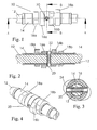
- Figure 1 is a side view of a camshaft of a first embodiment of the invention,
- Figure 2 is a section along the section line A-A in Figure 1,
- Figure 3 is a section along the section line B-B in Figure 1,
- Figure 4 is a perspective view of the camshaft of Figure 1 in its assembled state,
- Figure 5 is an exploded perspective view of the camshaft shown in Figures 1 to 4,
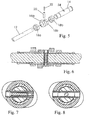
- Figure 6 is a section similar to that of Figure 2 showing a second embodiment of the invention,
- Figure 7 is a section similar to that of Figure 3 showing the second embodiment of the invention,
- Figure 8 is a section similar to that of Figure 3 showing a third embodiment of the invention, and
- Figure 9 is a section similar to that of Figure 2 illustrating a fourth embodiment of the invention.
- In all the figures, a
camshaft 10 is shown that comprises aninner drive shaft 12 journalled within anouter tube 14.Cams tube 14 for rotation therewith andfurther cams tube 14 and are connected for rotation with thedrive shaft 12 by means of ahollow pin 20 that passes with clearance through ahole 24 in theouter tube 14. This construction is common to all the described embodiments which only differ from one another in the manner in which thepin 20 is made to engage in thedrive shaft 12. - In the first embodiment shown in Figures 1 to 5, the bore of the connecting
pin 20 is formed with two different diameters, the central portion having a diameter that is smaller than that of the two ends. Acylindrical element 22 is inserted into thepin 20 after it has been inserted into thedrive shaft 12. Theelement 22 is an interference fit in the central portion of the connectingpin 20 and its insertion causes the outer diameter of thepin 20 to expand also, thus retaining thepin 20 in thedrive shaft 12. If the cylindrical element were to be removed, the pin would return to its original size and could be removed simply. - In the case of the second embodiment, shown in Figures 6 and 7, a tapered thread or an interference fit thread is provided on an element 122 that can be screwed into the bore of the connecting pin to fix the pin in position in the drive shaft. A slot or similar feature is required in one end of the connecting
pin 20 to prevent the pin from rotating as the threaded element 122 is screwed into position. - The third embodiment of Figure 8, is similar in concept to the first embodiment, but one or more spherical elements 222 are pushed into the bore of the connecting
pin 20 in order to expand it into the bore in thedrive shaft 12. - A fourth embodiment of the invention, shown in Figure 9, avoids the need to insert an additional component into the bore of the connecting
pin 20. Instead, the connecting pin has a mandrel 322 forced through it which is sized such that the central portion of the connectingpin 20 is expanded considerably beyond its elastic limit, and therefore remains an interference fit in thedrive shaft 12, even when the mandrel 322 has been removed. - In all the embodiments of the invention, the force applied to the connecting pin by the insertion of the locking elements or mandrel can be resisted on the end of the connecting pin itself and there will be no tendency to bend the drive shaft. For this reason, it suffices to support the
drive shaft 12 within the outer tube at only two axially spaced bearing locations, which may be formed either by suitably machined surfaces or an inserted bush. The need to machine the inner diameter oftube 14 and the outer diameter of thedrive shaft 12 accurately over their entire length is thus obviated.
Claims (10)
- A method of assembling a variable camshaft assembly having a first cam lobe (18) that can be moved relative to a second cam lobe (16), the assembly comprising a tube (14) to which the first cam lobe (18) is fixed and about which the second cam lobe (16) is free to rotate, a drive shaft (12) that passes through the bore of the tube (14) and a connecting pin (20) that passes with clearance through an aperture (24) in the tube (14) to couple the second cam lobe (16) for rotation with the drive shaft (12), characterised in that the method comprises inserting into holes in the second cam lobe and in the drive shaft a hollow connecting pin (20) having a constant outer diameter dimensioned to be a close fit in the holes, and expanding the outer diameter of the connecting pin (20) only within the region of the pin that lies within the drive shaft (12) so that an interference fit is generated with the drive shaft (12).
- A method as claimed in claim 1, wherein the connecting pin (20) has an inner diameter that varies along its length, being larger at its end engaging the cam lobe than at its region in line with the drive shaft, and the outer diameter of the pin is expanded by inserting into the pin an element (22) of larger outer diameter than the smaller inner diameter region of the connecting pin.
- A method as claimed in claim 2, wherein the inserted element (22) is cylindrical.
- A method as claimed in claim 2, wherein the inserted element (222) is spherical.
- A method as claimed in claim 2, wherein the inserted element (122) is a screw.
- A method as claimed in claim 2, wherein the inserted element is a mandrel that is withdrawn from the pin after it has locally stretched the pin beyond its elastic limit.
- A variable camshaft assembly having a first cam (18) that can be moved relative to a second cam (16), the assembly comprising a tube (14) fast in rotation with the first cam (18) and rotatably supporting the second cam (16) and a drive shaft (12) disposed within the tube (14) and coupled for rotation with the second cam (16) by means of a connecting pin (20) that passes with clearance through a hole (24) in the tube (14), characterised in that the connecting pin (20) is a hollow pin that is a sliding fit in the second cam (16) and that is expanded in situ to form an interference with the drive shaft (12).
- A variable camshaft as claimed in claim 7, wherein the drive shaft (12) is rotatably supported within the tube (14) at only two bearing locations and is spaced from the tube along the remainder of its length.
- A variable camshaft as claimed in claim 8, wherein the bearing locations include bushes arranged between the drive shaft and the surrounding tube.
- A variable camshaft as claimed in claim 8, wherein the drive shaft and the surrounding tube are machined to make direct contact with one another at the bearing locations.
Priority Applications (4)
| Application Number | Priority Date | Filing Date | Title |
|---|---|---|---|
| GB0111803A GB2375583B (en) | 2001-05-15 | 2001-05-15 | Variable camshaft assembly |
| US10/150,589 US6725818B2 (en) | 2001-05-15 | 2002-05-16 | Variable camshaft assembly |
| DE2002616235 DE60216235T2 (en) | 2002-05-17 | 2002-05-17 | Variable camshaft |
| EP02253494A EP1362986B1 (en) | 2001-05-15 | 2002-05-17 | Variable camshaft assembly |
Applications Claiming Priority (2)
| Application Number | Priority Date | Filing Date | Title |
|---|---|---|---|
| GB0111803A GB2375583B (en) | 2001-05-15 | 2001-05-15 | Variable camshaft assembly |
| EP02253494A EP1362986B1 (en) | 2001-05-15 | 2002-05-17 | Variable camshaft assembly |
Publications (2)
| Publication Number | Publication Date |
|---|---|
| EP1362986A1 EP1362986A1 (en) | 2003-11-19 |
| EP1362986B1 true EP1362986B1 (en) | 2006-11-22 |
Family
ID=31189530
Family Applications (1)
| Application Number | Title | Priority Date | Filing Date |
|---|---|---|---|
| EP02253494A Expired - Lifetime EP1362986B1 (en) | 2001-05-15 | 2002-05-17 | Variable camshaft assembly |
Country Status (3)
| Country | Link |
|---|---|
| US (1) | US6725818B2 (en) |
| EP (1) | EP1362986B1 (en) |
| GB (1) | GB2375583B (en) |
Cited By (2)
| Publication number | Priority date | Publication date | Assignee | Title |
|---|---|---|---|---|
| DE102008025781A1 (en) | 2008-05-29 | 2009-12-10 | Thyssenkrupp Presta Teccenter Ag | Adjustable camshaft arrangement |
| DE102008062041A1 (en) | 2008-12-12 | 2010-06-17 | Thyssenkrupp Presta Teccenter Ag | Adjustable camshaft arrangement |
Families Citing this family (52)
| Publication number | Priority date | Publication date | Assignee | Title |
|---|---|---|---|---|
| DE102004009074B3 (en) * | 2004-02-23 | 2005-07-07 | Thyssenkrupp Automotive Ag | Compound cam for camshaft for automobile engine assembled from 2 individual cam parts coupled together via intermediate ring |
| WO2006000004A2 (en) * | 2004-06-24 | 2006-01-05 | Avl List Gmbh | Internal combustion engine |
| DE102004039302A1 (en) * | 2004-08-13 | 2006-02-23 | Mahle Ventiltrieb Gmbh | Method for producing a camshaft |
| DE102004054301A1 (en) * | 2004-11-09 | 2006-05-11 | Mahle Ventiltrieb Gmbh | Camshaft for in particular motor vehicle engines |
| DE102005002395A1 (en) * | 2005-01-19 | 2006-07-27 | Mahle International Gmbh | Shaft device, in particular camshaft of motor vehicle engines |
| DE202005021715U1 (en) * | 2005-02-03 | 2009-07-02 | Mahle International Gmbh | Camshaft with mutually rotatable cam for motor vehicles in particular |
| DE102005004976A1 (en) * | 2005-02-04 | 2006-08-10 | Mahle International Gmbh | Camshaft with mutually rotatable cam for motor vehicle engines in particular |
| GB2423565A (en) * | 2005-02-23 | 2006-08-30 | Mechadyne Plc | Inner camshaft of SCP assembly receives drive via sleeve on outer tube |
| GB2424257A (en) * | 2005-03-18 | 2006-09-20 | Mechadyne Plc | Single cam phaser camshaft with adjustable connections between the inner shaft and associated cam lobes |
| EP1754913B2 (en) * | 2005-08-16 | 2013-05-29 | Mahle International GmbH | Adjustable camshaft |
| GB2431977A (en) * | 2005-11-02 | 2007-05-09 | Mechadyne Plc | Camshaft assembly |
| DE102005062208B4 (en) * | 2005-12-24 | 2015-08-06 | Mahle International Gmbh | camshaft |
| DE102006008532A1 (en) * | 2006-02-22 | 2007-08-30 | Thyssenkrupp Automotive Ag | Camshaft e.g. eccentric shaft, manufacturing method for internal combustion engine, involves shielding support unit against cam, such that chips arising during chip removing process are not penetrated into intermediate space |
| DE102006013813B4 (en) | 2006-03-23 | 2011-05-12 | Mahle International Gmbh | Camshaft of particular motor vehicle internal combustion engines |
| DE102006034226A1 (en) * | 2006-07-25 | 2008-01-31 | GM Global Technology Operations, Inc., Detroit | camshaft |
| GB2444943B (en) | 2006-12-19 | 2011-07-13 | Mechadyne Plc | Camshaft and phaser assembly |
| EP2171222B1 (en) * | 2007-07-02 | 2017-11-29 | BorgWarner Inc. | Concentric cam with check valves in the spool for a phaser |
| WO2009024170A1 (en) * | 2007-08-22 | 2009-02-26 | Fev Motorentechnik Gmbh | Internal combustion engine having a cam-controlled variable valve train |
| US7895743B2 (en) * | 2007-12-18 | 2011-03-01 | Caterpillar Inc. | Refurbished camshaft and method |
| US7895982B2 (en) * | 2007-12-18 | 2011-03-01 | Caterpillar Inc. | Refurbished camshaft and method |
| DE102008052413A1 (en) * | 2008-01-18 | 2009-07-23 | Schaeffler Kg | Valve gear of an internal combustion engine |
| GB2456792A (en) | 2008-01-24 | 2009-07-29 | Mechadyne Plc | Single cam phaser camshaft assembly |
| US7849829B2 (en) | 2008-03-12 | 2010-12-14 | Gm Global Technology Operations, Inc. | Concentric camshaft with independent bearing surface for floating lobes |
| US8028666B2 (en) | 2008-03-12 | 2011-10-04 | GM Global Technology Operations LLC | Concentric camshaft with bearing sleeve and method of debris removal |
| US7866293B2 (en) * | 2008-03-12 | 2011-01-11 | GM Global Technology Operations LLC | Concentric camshaft with improved torque resistance |
| US7966983B2 (en) * | 2008-04-10 | 2011-06-28 | GM Global Technology Operations LLC | Concentric camshaft with varying wall geometry and method of assembly |
| US20100012060A1 (en) * | 2008-07-21 | 2010-01-21 | Gm Global Technology Operations, Inc. | Split Lobe Design of Concentric Camshaft |
| DE102008053723B4 (en) * | 2008-10-29 | 2023-12-07 | Neumayer Tekfor Engineering Gmbh | Built camshaft |
| GB2467333A (en) | 2009-01-30 | 2010-08-04 | Mechadyne Plc | Single camshaft phaser and camshaft for i.c. engines |
| WO2010096437A2 (en) | 2009-02-17 | 2010-08-26 | Cummins Inc. | Variable valve actuation apparatus, system, and method |
| US8156910B2 (en) * | 2009-02-20 | 2012-04-17 | GM Global Technology Operations LLC | Concentric camshaft and method of assembly |
| DE102009041426A1 (en) | 2009-09-16 | 2011-05-19 | Thyssenkrupp Presta Teccenter Ag | Camshaft with variable valve opening duration |
| US8235019B2 (en) * | 2009-11-11 | 2012-08-07 | GM Global Technology Operations LLC | Engine having concentric camshaft with differential valve lift |
| JP4883330B2 (en) * | 2009-11-25 | 2012-02-22 | 三菱自動車工業株式会社 | Variable valve operating device for internal combustion engine |
| DE102009055868A1 (en) * | 2009-11-26 | 2011-06-01 | Neumayer Tekfor Holding Gmbh | camshaft |
| WO2011091129A2 (en) | 2010-01-22 | 2011-07-28 | Borgwarner Inc. | Directly communicated turbocharger |
| KR101209733B1 (en) * | 2010-09-01 | 2012-12-07 | 현대자동차주식회사 | Variable valve lift appratus |
| US8448617B2 (en) | 2010-10-20 | 2013-05-28 | GM Global Technology Operations LLC | Engine including camshaft with partial lobe |
| US8683965B2 (en) * | 2011-05-10 | 2014-04-01 | Gm Global Technology Operations, Llc | Engine assembly including camshaft actuator |
| DE102011052822A1 (en) * | 2011-08-18 | 2013-02-21 | Thyssenkrupp Presta Teccenter Ag | Camshaft, in particular for motor vehicle engines |
| DE102012220652A1 (en) | 2012-11-13 | 2014-05-15 | Mahle International Gmbh | camshaft |
| CN103061846B (en) * | 2013-01-25 | 2015-02-25 | 唐山学院 | Variable air intake valve different lift device of motor |
| CN103790669B (en) * | 2014-01-23 | 2017-07-28 | 长城汽车股份有限公司 | For the valve actuating mechanism of engine and the vehicle with it |
| CN103758605B (en) * | 2014-01-23 | 2016-04-13 | 长城汽车股份有限公司 | For motor distribution device and there is its vehicle |
| CN103758980A (en) * | 2014-02-12 | 2014-04-30 | 太仓斯普宁精密机械有限公司 | Camshaft with angle easy to adjust |
| CN103967549A (en) * | 2014-05-21 | 2014-08-06 | 中国第一汽车股份有限公司 | One-cylinder multiple-cam combined type cam shaft |
| KR101427904B1 (en) * | 2014-07-10 | 2014-08-08 | 주식회사 미보 | Concentric cam shaft and manufacturing method of rotation cam and fixed cam for concentric cam shaft |
| DE102015215292A1 (en) * | 2015-08-11 | 2017-02-16 | Thyssenkrupp Ag | Method and device for mounting an adjustable camshaft |
| DE112016004372T5 (en) | 2015-11-06 | 2018-06-07 | Borgwarner Inc. | VALVE CONTROL SYSTEM THAT PROVIDES A VARIABLE VALVE HUB AND / OR VARIABLE VALVE TIME CONTROL |
| CN108442989B (en) * | 2018-03-15 | 2019-07-12 | 罗守磊 | A kind of engine exploitation adjustable convex wheel shaft |
| USD902252S1 (en) * | 2018-06-04 | 2020-11-17 | Transportation IP Holdings, LLP | Modular cam shaft |
| CN115013105A (en) * | 2022-06-06 | 2022-09-06 | 苏州三林万腾汽车科技有限公司 | Assembled camshaft |
Family Cites Families (17)
| Publication number | Priority date | Publication date | Assignee | Title |
|---|---|---|---|---|
| US3897760A (en) * | 1973-10-09 | 1975-08-05 | Charles A Hisserich | Valve timing overlap control for internal combustion engines |
| JPS609803A (en) * | 1983-06-30 | 1985-01-18 | Nippon Piston Ring Co Ltd | Production of assembled cam shaft |
| JPS6017214A (en) * | 1983-07-11 | 1985-01-29 | Toyota Motor Corp | Valve gear for internal-combustion engine |
| US5101554A (en) * | 1986-10-01 | 1992-04-07 | Emitec Gesellschaft Fur Emissionstechnologie Mbh | Process for producing an assembled camshaft as well as assembled camshaft consisting of a shaft tube and slid-on elements |
| US5259268A (en) * | 1987-02-10 | 1993-11-09 | Gesenkschmiede Schneider Gmbh | Hollowshaft and method for the production thereof |
| WO1992002739A1 (en) * | 1990-07-27 | 1992-02-20 | Mettler Friedli Karl | Assembly of a cylindrical body made to finished dimensions |
| AT395688B (en) * | 1991-02-13 | 1993-02-25 | Miba Sintermetall Ag | METHOD FOR PRODUCING A MOLDED PART BY SINTERING |
| US5235939A (en) * | 1992-11-05 | 1993-08-17 | Ford Motor Company | Automotive engine torsional pulse enhancer |
| DE4404708C2 (en) * | 1993-02-15 | 2000-04-13 | Unisia Jecs Corp | Valve control device for an internal combustion engine |
| JPH07102914A (en) * | 1993-03-03 | 1995-04-18 | Peter Amborn | Cam shaft assembly with mutually positioned shaft elements and method of manufacturing the same |
| FR2709786B1 (en) * | 1993-09-09 | 1995-11-17 | Renault | Camshaft for internal combustion engine. |
| DE4416505A1 (en) * | 1994-05-10 | 1995-11-16 | Bayerische Motoren Werke Ag | Cam shaft with turnable cams |
| JP3394357B2 (en) * | 1995-05-10 | 2003-04-07 | Ntn株式会社 | Camshaft |
| US5729899A (en) * | 1996-10-09 | 1998-03-24 | Kaywood Products Corporation | Camshaft assembly and method of making same |
| US5778841A (en) * | 1997-02-26 | 1998-07-14 | Cummins Engine Company, Inc. | Camshaft for internal combustion engines |
| GB2324487A (en) * | 1997-04-26 | 1998-10-28 | Mechadyne Ltd | Method of manufacturing a multi-component camshaft |
| DE19757504B4 (en) * | 1997-12-23 | 2005-03-31 | Daimlerchrysler Ag | Built camshaft for an internal combustion engine |
-
2001
- 2001-05-15 GB GB0111803A patent/GB2375583B/en not_active Expired - Fee Related
-
2002
- 2002-05-16 US US10/150,589 patent/US6725818B2/en not_active Expired - Lifetime
- 2002-05-17 EP EP02253494A patent/EP1362986B1/en not_active Expired - Lifetime
Cited By (2)
| Publication number | Priority date | Publication date | Assignee | Title |
|---|---|---|---|---|
| DE102008025781A1 (en) | 2008-05-29 | 2009-12-10 | Thyssenkrupp Presta Teccenter Ag | Adjustable camshaft arrangement |
| DE102008062041A1 (en) | 2008-12-12 | 2010-06-17 | Thyssenkrupp Presta Teccenter Ag | Adjustable camshaft arrangement |
Also Published As
| Publication number | Publication date |
|---|---|
| GB0111803D0 (en) | 2001-07-04 |
| US6725818B2 (en) | 2004-04-27 |
| GB2375583B (en) | 2004-09-01 |
| GB2375583A (en) | 2002-11-20 |
| US20020170514A1 (en) | 2002-11-21 |
| EP1362986A1 (en) | 2003-11-19 |
Similar Documents
| Publication | Publication Date | Title |
|---|---|---|
| US6725818B2 (en) | Variable camshaft assembly | |
| CN101142378B (en) | camshaft assembly | |
| JP3310984B2 (en) | Plain bearing | |
| KR100348824B1 (en) | tilt hinge | |
| US6220759B1 (en) | Positioning pivot | |
| US5308207A (en) | Retaining ring and shaft for securing a component thereon | |
| US5826461A (en) | Camshaft assembly and method of making the same | |
| US20070269157A1 (en) | Bearing Assemblies for the Pinion Shaft of an Axle Differential | |
| US7069892B2 (en) | Camshaft for automotive engines in particular | |
| KR20080012238A (en) | Manufacturing method of simple planetary gear device and simple planetary gear device | |
| US5729899A (en) | Camshaft assembly and method of making same | |
| US6804862B2 (en) | Hinge system | |
| EP2096737B1 (en) | Submersible motor | |
| CN106481630A (en) | Machine element fastening system | |
| US7845075B2 (en) | Method for manufacturing a camshaft | |
| JP4909276B2 (en) | Camshaft for automobile engine | |
| US3047318A (en) | Device for the precision mounting of a gear on a shaft | |
| US6907667B2 (en) | Method for facilitating the assembly of a universal joint | |
| US6289765B1 (en) | Roller follower shaft retention | |
| US5263249A (en) | Lightweight composite camshaft, method of assembly | |
| EP4479668A1 (en) | Rotor tube assembly for a fluid valve actuator and method for assembling a rotor tube assembly | |
| KR200357309Y1 (en) | Free hinge for a door | |
| JP2002005152A (en) | Tilting hinge | |
| DE19859307A1 (en) | Bearing with adjustable play, with contact region between bearing ring and casing to create narrow-tolerance built-in mass | |
| JP7079756B2 (en) | handrail |
Legal Events
| Date | Code | Title | Description |
|---|---|---|---|
| PUAI | Public reference made under article 153(3) epc to a published international application that has entered the european phase |
Free format text: ORIGINAL CODE: 0009012 |
|
| AK | Designated contracting states |
Kind code of ref document: A1 Designated state(s): AT BE CH CY DE DK ES FI FR GB GR IE IT LI LU MC NL PT SE TR |
|
| AX | Request for extension of the european patent |
Extension state: AL LT LV MK RO SI |
|
| 17P | Request for examination filed |
Effective date: 20040408 |
|
| AKX | Designation fees paid |
Designated state(s): DE FR GB |
|
| GRAP | Despatch of communication of intention to grant a patent |
Free format text: ORIGINAL CODE: EPIDOSNIGR1 |
|
| GRAS | Grant fee paid |
Free format text: ORIGINAL CODE: EPIDOSNIGR3 |
|
| GRAA | (expected) grant |
Free format text: ORIGINAL CODE: 0009210 |
|
| AK | Designated contracting states |
Kind code of ref document: B1 Designated state(s): DE FR |
|
| REF | Corresponds to: |
Ref document number: 60216235 Country of ref document: DE Date of ref document: 20070104 Kind code of ref document: P |
|
| ET | Fr: translation filed | ||
| PLBE | No opposition filed within time limit |
Free format text: ORIGINAL CODE: 0009261 |
|
| STAA | Information on the status of an ep patent application or granted ep patent |
Free format text: STATUS: NO OPPOSITION FILED WITHIN TIME LIMIT |
|
| 26N | No opposition filed |
Effective date: 20070823 |
|
| REG | Reference to a national code |
Ref country code: FR Ref legal event code: CJ Effective date: 20131015 Ref country code: FR Ref legal event code: TP Owner name: MECHADYNE INTERNATIONAL LIMITED, GB Effective date: 20131015 Ref country code: FR Ref legal event code: CD Owner name: MECHADYNE INTERNATIONAL LIMITED, GB Effective date: 20131015 |
|
| REG | Reference to a national code |
Ref country code: DE Ref legal event code: R082 Ref document number: 60216235 Country of ref document: DE Representative=s name: PATENTANWAELTE TER SMITTEN EBERLEIN-VAN HOOF R, DE Ref country code: DE Ref legal event code: R082 Ref document number: 60216235 Country of ref document: DE Representative=s name: PATENTANWAELTE TER SMITTEN EBERLEIN RUETTEN PA, DE |
|
| REG | Reference to a national code |
Ref country code: FR Ref legal event code: PLFP Year of fee payment: 15 |
|
| REG | Reference to a national code |
Ref country code: FR Ref legal event code: PLFP Year of fee payment: 16 |
|
| REG | Reference to a national code |
Ref country code: FR Ref legal event code: PLFP Year of fee payment: 17 |
|
| PGFP | Annual fee paid to national office [announced via postgrant information from national office to epo] |
Ref country code: DE Payment date: 20190522 Year of fee payment: 18 |
|
| PGFP | Annual fee paid to national office [announced via postgrant information from national office to epo] |
Ref country code: FR Payment date: 20190521 Year of fee payment: 18 |
|
| REG | Reference to a national code |
Ref country code: DE Ref legal event code: R082 Ref document number: 60216235 Country of ref document: DE Representative=s name: TERPATENT PATENTANWAELTE TER SMITTEN EBERLEIN-, DE |
|
| REG | Reference to a national code |
Ref country code: DE Ref legal event code: R119 Ref document number: 60216235 Country of ref document: DE |
|
| PG25 | Lapsed in a contracting state [announced via postgrant information from national office to epo] |
Ref country code: FR Free format text: LAPSE BECAUSE OF NON-PAYMENT OF DUE FEES Effective date: 20200531 |
|
| PG25 | Lapsed in a contracting state [announced via postgrant information from national office to epo] |
Ref country code: DE Free format text: LAPSE BECAUSE OF NON-PAYMENT OF DUE FEES Effective date: 20201201 |