EP1362903B1 - Seal material - Google Patents
Seal material Download PDFInfo
- Publication number
- EP1362903B1 EP1362903B1 EP01970319.8A EP01970319A EP1362903B1 EP 1362903 B1 EP1362903 B1 EP 1362903B1 EP 01970319 A EP01970319 A EP 01970319A EP 1362903 B1 EP1362903 B1 EP 1362903B1
- Authority
- EP
- European Patent Office
- Prior art keywords
- sealing member
- permeability
- needle
- foam
- thickness
- Prior art date
- Legal status (The legal status is an assumption and is not a legal conclusion. Google has not performed a legal analysis and makes no representation as to the accuracy of the status listed.)
- Expired - Lifetime
Links
- 239000000463 material Substances 0.000 title description 3
- 238000007789 sealing Methods 0.000 claims description 90
- 230000035699 permeability Effects 0.000 claims description 46
- 229920001821 foam rubber Polymers 0.000 claims description 9
- 239000006260 foam Substances 0.000 description 40
- 230000000052 comparative effect Effects 0.000 description 12
- XLYOFNOQVPJJNP-UHFFFAOYSA-N water Substances O XLYOFNOQVPJJNP-UHFFFAOYSA-N 0.000 description 11
- 238000009950 felting Methods 0.000 description 8
- 238000004080 punching Methods 0.000 description 8
- 238000000034 method Methods 0.000 description 7
- JOYRKODLDBILNP-UHFFFAOYSA-N Ethyl urethane Chemical compound CCOC(N)=O JOYRKODLDBILNP-UHFFFAOYSA-N 0.000 description 6
- 238000004519 manufacturing process Methods 0.000 description 6
- 229920003002 synthetic resin Polymers 0.000 description 5
- 239000000057 synthetic resin Substances 0.000 description 5
- 238000010521 absorption reaction Methods 0.000 description 4
- 239000002390 adhesive tape Substances 0.000 description 3
- 238000005259 measurement Methods 0.000 description 3
- AZUYLZMQTIKGSC-UHFFFAOYSA-N 1-[6-[4-(5-chloro-6-methyl-1H-indazol-4-yl)-5-methyl-3-(1-methylindazol-5-yl)pyrazol-1-yl]-2-azaspiro[3.3]heptan-2-yl]prop-2-en-1-one Chemical compound ClC=1C(=C2C=NNC2=CC=1C)C=1C(=NN(C=1C)C1CC2(CN(C2)C(C=C)=O)C1)C=1C=C2C=NN(C2=CC=1)C AZUYLZMQTIKGSC-UHFFFAOYSA-N 0.000 description 2
- NIXOWILDQLNWCW-UHFFFAOYSA-N acrylic acid group Chemical group C(C=C)(=O)O NIXOWILDQLNWCW-UHFFFAOYSA-N 0.000 description 2
- 230000000903 blocking effect Effects 0.000 description 2
- DQXBYHZEEUGOBF-UHFFFAOYSA-N but-3-enoic acid;ethene Chemical compound C=C.OC(=O)CC=C DQXBYHZEEUGOBF-UHFFFAOYSA-N 0.000 description 2
- 238000007796 conventional method Methods 0.000 description 2
- 238000005520 cutting process Methods 0.000 description 2
- 230000005489 elastic deformation Effects 0.000 description 2
- 239000005038 ethylene vinyl acetate Substances 0.000 description 2
- 229920001200 poly(ethylene-vinyl acetate) Polymers 0.000 description 2
- 230000006835 compression Effects 0.000 description 1
- 238000007906 compression Methods 0.000 description 1
- 230000002950 deficient Effects 0.000 description 1
- 230000002706 hydrostatic effect Effects 0.000 description 1
- 238000009413 insulation Methods 0.000 description 1
- 239000002184 metal Substances 0.000 description 1
- 238000003825 pressing Methods 0.000 description 1
- 230000000717 retained effect Effects 0.000 description 1
- 239000003566 sealing material Substances 0.000 description 1
- 229920002050 silicone resin Polymers 0.000 description 1
Images


Classifications
-
- B—PERFORMING OPERATIONS; TRANSPORTING
- B29—WORKING OF PLASTICS; WORKING OF SUBSTANCES IN A PLASTIC STATE IN GENERAL
- B29C—SHAPING OR JOINING OF PLASTICS; SHAPING OF MATERIAL IN A PLASTIC STATE, NOT OTHERWISE PROVIDED FOR; AFTER-TREATMENT OF THE SHAPED PRODUCTS, e.g. REPAIRING
- B29C44/00—Shaping by internal pressure generated in the material, e.g. swelling or foaming ; Producing porous or cellular expanded plastics articles
- B29C44/34—Auxiliary operations
- B29C44/56—After-treatment of articles, e.g. for altering the shape
- B29C44/5627—After-treatment of articles, e.g. for altering the shape by mechanical deformation, e.g. crushing, embossing, stretching
- B29C44/5663—After-treatment of articles, e.g. for altering the shape by mechanical deformation, e.g. crushing, embossing, stretching by perforating the foam, e.g. to open the cells
-
- C—CHEMISTRY; METALLURGY
- C09—DYES; PAINTS; POLISHES; NATURAL RESINS; ADHESIVES; COMPOSITIONS NOT OTHERWISE PROVIDED FOR; APPLICATIONS OF MATERIALS NOT OTHERWISE PROVIDED FOR
- C09K—MATERIALS FOR MISCELLANEOUS APPLICATIONS, NOT PROVIDED FOR ELSEWHERE
- C09K3/00—Materials not provided for elsewhere
- C09K3/10—Materials in mouldable or extrudable form for sealing or packing joints or covers
-
- C—CHEMISTRY; METALLURGY
- C09—DYES; PAINTS; POLISHES; NATURAL RESINS; ADHESIVES; COMPOSITIONS NOT OTHERWISE PROVIDED FOR; APPLICATIONS OF MATERIALS NOT OTHERWISE PROVIDED FOR
- C09K—MATERIALS FOR MISCELLANEOUS APPLICATIONS, NOT PROVIDED FOR ELSEWHERE
- C09K3/00—Materials not provided for elsewhere
- C09K3/10—Materials in mouldable or extrudable form for sealing or packing joints or covers
- C09K3/1006—Materials in mouldable or extrudable form for sealing or packing joints or covers characterised by the chemical nature of one of its constituents
- C09K3/1021—Polyurethanes or derivatives thereof
-
- C—CHEMISTRY; METALLURGY
- C09—DYES; PAINTS; POLISHES; NATURAL RESINS; ADHESIVES; COMPOSITIONS NOT OTHERWISE PROVIDED FOR; APPLICATIONS OF MATERIALS NOT OTHERWISE PROVIDED FOR
- C09K—MATERIALS FOR MISCELLANEOUS APPLICATIONS, NOT PROVIDED FOR ELSEWHERE
- C09K2200/00—Chemical nature of materials in mouldable or extrudable form for sealing or packing joints or covers
- C09K2200/06—Macromolecular organic compounds, e.g. prepolymers
- C09K2200/0642—Copolymers containing at least three different monomers
Definitions
- the present invention relates to a sealing member to be interposed between parts for sealing the parts and, more particularly, to a sealing member made of rubber foam.
- sealing members made of synthetic resin foam or rubber foam are used for sealing various portions.
- sealing members of this type are widely used for sealing parts, such as a back of a wall-mounted type unit of an air conditioner, a periphery of a ceiling-mounted built-in type unit of an air conditioner, a casing for an outdoor unit of an air conditioner, a front panel door for a vending machine, a back of a refrigerator, and a CD-ROM device.
- sealing members are used for sealing parts in a motor car, such as a wind dam (air dam), a periphery of a sunroof, a door speaker box, a mounting portion for an outside mirror, and a cowl top seal.
- a wind dam air dam
- Such sealing members are also used for sealing parts in a house, such as roof tiles, a periphery of a sash, a periphery of a shutter, a joint for exterior panels, and a joint for metal roof plates.
- the sealing members are generally made of synthetic resin foam or rubber foam, for example urethane foam or sponge rubber foam.
- cells of the foam are mainly closed cells, the closed cells have disadvantages such as poor dimensional stability.
- the sealing members are previously processed by roll crushing, vacuum crushing, or impact crushing to create micro cracks so as to break a part of the closed cells (see US 5 705 115 ), thereby providing desired permeability and thus improving the dimensional stability.
- Fig. 2 is a schematic view for explaining a conventional example of manufacturing process in which sealing members are pressed by pairs of rolls. As shown, a foam body 1 is sliced into a plurality of thin plates 2 and the respective thin plates 2 are pressed in the thickness direction between the pairs of rolls 3, 3, thereby manufacturing the sealing members having desired permeability.
- the sealing member of the present invention is a sealing member to be interposed between parts and which is composed of rubber foam and is characterized in that the ratio of the permeability A in a compressing direction at non-compressed state to the permeability B in a direction perpendicular to the compressing direction at 50% compressed state in the compressing direction, that is A/B, is 1-40.
- the sealing member according to the present invention has greater permeability in the vertical direction and smaller permeability in the lateral direction, the sealing member has stable air tightness and waterproof.
- the sound absorption can be controlled by controlling the permeability in the vertical direction.
- the permeability in the vertical direction is substantially constant even with variation in compressing ratio while the permeability in the lateral direction varies according to the compressing ratio.
- the compressing ratio in applications as sealing member extends in a wide range from 5% to 95%.
- the permeability at 50% compressed state is employed for defining the permeability in the lateral direction because 50% is the average compressing ratio.
- the permeability A in the vertical direction at non-compressed state is 30 L/min or less and the permeability B in the lateral direction at 50 % compressed state is 10 L/min or less.
- the ratio of the permeability A in the compressing direction at non-compressed state to the permeability B in the direction perpendicular to the compressing direction at 50% compressed state, that is A/B, is 2-20.
- the sealing member is preferably formed with needle holes in the compressing direction. It is preferable that the needle holes are
- the gauge of needles of said needle punch is 20-150 needles per square centimeter.
- the shank of each needle of the needle punch is 1-3 mm in thickness and the blade of each needle of the needle punch is 0.2-3 mm in thickness.
- Sealing members of the present invention are made of rubber foam such as EPDM (ethylene-propylene-diene-methylene linkage) foam, EVA (ethylene vinyl acetate) foam, and silicone resin foam.
- EPDM ethylene-propylene-diene-methylene linkage
- EVA ethylene vinyl acetate
- silicone resin foam a foam that is used for the aforementioned various applications.
- the dimension of each sealing member is not particularly limited, but normally about 1.0 through 100 mm in thickness.
- the expansion ratio of the rubber foam is 5-30 times while the expansion ratio of a synthetic resin foam such as urethane foam is 3-40 times.
- the sealing members preferably have needle holes or apertures formed in the vertical direction by using needle punches, thereby increasing the air permeability in the vertical direction.
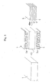
- Fig. 1 is a schematic view showing the process by needle punches 5, 5, in which a foam body 1 is vertically sandwiched between the needle punches 5, 5 and is pierced with needles 5a of the needle punches 5 so as to form needle holes in the vertical direction. After that, the foam body 1 is sliced into a plurality of thin plates as sealing members 6.
- the gauge of needles of each needle punch is 20-150 needles per a square centimeter.
- felting needles are suitably used, regardless of whether the needles have a barb or barbs or not and whether the needles have an intermediate blade or not.
- Fig. 3a is a front view showing a typical needle, that is a felting needle
- Fig. 3b is a sectional view taken along a line B-B in Fig. 3a
- Fig. 3c is a sectional view taken along a line C-C in Fig. 3a
- Fig. 3d is a sectional view taken along a line D-D in Fig. 3a
- Fig. 3d two examples as the configuration of blades are shown in which one is a triangle rod blade 7C and the other is a cylindrical blade 7C'.
- the felting needle 7 comprises a shank 7A, a blade 7C (7C'), and an intermediate blade 7B between the shank 7A and the blade 7C (7C').
- the thickness of the shank is 1-3 mm and the thickness of the blade is 0.2-3 mm, particularly 0.4-1.8 mm, but the thickness depends on the material of the needle.
- the thickness of the shank of the needle is indicated as a diameter R 1 of the shank 7A in Fig. 3b and the thickness of the blade is indicated as a height R 2 of a triangle in section of the blade 7C. In case of a blade 7C' having circular section, the thickness is indicated as a diameter R 2 of the circle.
- the length of the needle is indicated as a length L from the shank 7A to the blade 7C.
- the needle punches are arranged above and below the foam body as shown in Fig. 1 so as to punch the foam body from above and below.
- the upper and lower needle punches may punch the foam body at the same time.
- the lower needle punch may punch after the upper needle punch.
- the upper needle punch may punch after the lower needle punch. It should be noted that only upper or lower needle punch may be used.
- the ratio of the permeability A in the vertical direction at non-compressed state to the permeability B in the lateral direction at 50% compressed state, that is A/B, is 1-40, preferably 2-20, more preferably 5-10.
- the permeability in the vertical direction is preferably 20-1 times, more preferably 10-1 times, particularly 5-1 times of the permeability in the lateral direction.
- the sealing member has preferably the low permeability both in the vertical direction and in the lateral direction when the sealing member is used for sealing air and water tightly.
- the permeability A in the vertical direction is 30 L/min or less and the permeability B in the lateral direction at 50% compressed state is 10 L/min or less.
- the permeability When requiring extremely high water sealing capability and high air tightness, it is desirable that the permeability is as low as possible. However, to ensure the elastic restoring property of the sealing member, it is preferable that the permeability is 0.01 L/mim or more. Therefore, it is preferable that the permeability A in the vertical direction is 0.1-1.0 L/min and the permeability B in the lateral direction at 50 % compressed state is 0.01-1.0 L/min.
- the sealing member according to the present invention may have at least one adhesive tape applied thereto for adhesion.
- the permeability in the vertical direction is in the aforementioned range, air can be easily released selectively in the vertical direction during applying an adhesive tape to the sealing member, thereby preventing air from being trapped between the adhesive tape and the foam and speeding up the applying operation.
- the productivity of the sealing member with the tape is improved and the fraction defective is reduced.
- An EPDM foam of 10 x 100 x 100 cm having an expansion ratio of 30 times is processed by needle punching according to the method shown in Fig. 1 and then sliced into a plurality of pieces as sealing members of 1.0 cm in thickness. It should be noted that main conditions are as follows:
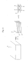
- the measurement of permeability of the sealing member was conducted according to JIS K 6400. Concretely, the permeability B in the lateral direction at 50 % compressed state was measured by the following steps: cutting out a ring-shaped sample 10 as shown in Fig. 4a ; compressing and keeping the sample 10 at 50 % compressed state between a supporting board 11 and an acrylic board 12 as shown in Fig. 4b ; and sucking a central area of the sample.
- the sample has a thickness of 10 mm, an inner diameter of 60 mm, and an outer diameter of 80 mm.
- the permeability A in the vertical direction at non-compressed state was measured by the following steps: cutting out a sample of 10 mm x 100 mm x 100 mm; disposing the sample on an inlet of a vacuum chamber in such a manner as to close the inlet; and sucking the inside of the vacuum chamber.
- the water sealing capability of the sealing member under the hydrostatic pressure was measured as shown in Fig. 5 .
- a sample 20 was prepared by punching the sealing member into a U-like shape.
- the sample 20 was sandwiched between two acrylic boards 21, 21 and retained by bolts 22 in such a manner that the sample 20 was compressed to have 50%, 70%, or 80% thickness of the initial or original thickness. After left for 24 hours, water was poured from the top to have maximum depth of 100 mm and the water leakage was observed visually.
- Table 1 indicates load for compressing the sample into 50% compressed state.
- Sealing members were manufactured in the same manner as Example 1, except that an urethane foam having an expansion ratio of 10 times was used instead of the EPDM foam and processed under the following conditions of needle punching.
- Sealing members were manufactured in the same manner as Example 1, except that an EPDM foam having an expansion ratio of 13 times was used and processed under the following conditions of needle punching.
- Sealing members were manufactured in the same manner as Example 1, except that an EPDM foam having an expansion ratio of 13 times was used and processed under the following conditions of needle punching.
- the same urethane and EPDM foams as used in Examples 2, 3 were processed by roll crushing shown in Fig. 2 , thereby manufacturing sealing members.
- the characteristics of the sealing members were evaluated. Three pairs of rolls were provided, the diameter of each roll was 100 mm, and the feeding speed was 8 m/min. The first clearance between rolls was 8 mm, the second clearance was 6 mm, and the third clearance was 3 mm. The results are shown in Table 1.
- Sealing members were manufactured in the same manner as Example 1, except that an EPDM foam having an expansion ratio of 13 times was used and processed under the needle punching conditions as shown in Table 1. The characteristics of the sealing members were evaluated. The results are shown in Table 1.
- Example 5 The same EPDM foam as used in Example 5 was processed by roll crushing in the same manner as Comparative Example 1, thereby manufacturing sealing members. The characteristics of the sealing members were evaluated and the results are shown in Table 1. In addition, the sound absorbing coefficient of normal incident sound was measured and the result is shown in Fig. 6 .
- Example 5 The same EPDM foam as used in Example 5 was not processed by any method of breaking cells so as to remain all closed cells. The characteristics were evaluated and the results are shown in Table 1. In addition, the sound absorbing coefficient of normal incident sound was measured and the result is shown in Fig. 6 .
- the present invention can provide a sealing member having low permeability in the direction perpendicular to the compressing direction and having excellent water sealing capability and sound absorption.
- the sealing member has increased permeability in the compressing direction and can be elastically deformed in the compressing direction at an increased rate.
Landscapes
- Chemical & Material Sciences (AREA)
- Engineering & Computer Science (AREA)
- Materials Engineering (AREA)
- Organic Chemistry (AREA)
- Mechanical Engineering (AREA)
- Sealing Material Composition (AREA)
- Gasket Seals (AREA)
- Building Environments (AREA)
- Manufacture Of Porous Articles, And Recovery And Treatment Of Waste Products (AREA)
Description
- The present invention relates to a sealing member to be interposed between parts for sealing the parts and, more particularly, to a sealing member made of rubber foam.
- In housing exterior panels, electrical appliances such as air conditioners, or motor cars, sealing members made of synthetic resin foam or rubber foam are used for sealing various portions. For example, sealing members of this type are widely used for sealing parts, such as a back of a wall-mounted type unit of an air conditioner, a periphery of a ceiling-mounted built-in type unit of an air conditioner, a casing for an outdoor unit of an air conditioner, a front panel door for a vending machine, a back of a refrigerator, and a CD-ROM device. In addition, such sealing members are used for sealing parts in a motor car, such as a wind dam (air dam), a periphery of a sunroof, a door speaker box, a mounting portion for an outside mirror, and a cowl top seal. Such sealing members are also used for sealing parts in a house, such as roof tiles, a periphery of a sash, a periphery of a shutter, a joint for exterior panels, and a joint for metal roof plates.
- The sealing members are generally made of synthetic resin foam or rubber foam, for example urethane foam or sponge rubber foam.
- Though cells of the foam are mainly closed cells, the closed cells have disadvantages such as poor dimensional stability.
- Therefore, the sealing members are previously processed by roll crushing, vacuum crushing, or impact crushing to create micro cracks so as to break a part of the closed cells (see
US 5 705 115 ), thereby providing desired permeability and thus improving the dimensional stability. -
Fig. 2 is a schematic view for explaining a conventional example of manufacturing process in which sealing members are pressed by pairs of rolls. As shown, afoam body 1 is sliced into a plurality ofthin plates 2 and the respectivethin plates 2 are pressed in the thickness direction between the pairs ofrolls - The above conventional sealing member has the following disadvantages:
- i) In case of pressing process by means of the aforementioned roll crushing, pressure is applied in the thickness direction of the sealing member so that cells are easy to be broken in a direction perpendicular to the thickness direction of the sealing member. Normally, the sealing member is interposed between parts in such a manner that the sealing member is compressed in its thickness direction in order to block the flow of air or water in a direction perpendicular to the direction of compressing the sealing member. Therefore, a large number of broken cells in the direction perpendicular to the thickness direction lead to reduction in air blocking property and/or water blocking property of the sealing member.
It should be noted that the compressing direction will be sometimes referred to as "vertical direction" and the direction perpendicular to the compressing direction will be sometimes referred to as "lateral direction". - ii) When the sealing member is compressed, air within the sealing member flows out through micro cracks produced during breaking cells, so as to reduce the thickness of the sealing member. Then, as the compressive force is cancelled, air flows into the sealing member through the micro cracks so as to restore the thickness of the sealing member.
However, a large number of micro cracks extend in the lateral direction in the sealing member having a large number of broken cells in the lateral direction, so that air flows in the lateral direction within the sealing member. Since the air flow paths have great lateral length, the speed of air flowing into or out of the sealing member is slowed down and, therefore, deformation in thickness of the sealing member is also slowed down. That is, the rate of elastic deformation of the sealing member according to the external force is reduced. - iii) As the amount of micro cracks in the vertical direction is increased, air also flows into or out of the sealing member in the vertical direction, thereby increasing the rate of elastic deformation of the sealing member. When the air permeability in the vertical direction of the sealing member is increased by compressing the sealing member according to a conventional method such as roll crushing, broken cells in the lateral direction are correspondingly increased. In this case, there is a possibility of lack of properties of the sealing member such as sound absorption and impact absorption and air tightness. In addition, it is difficult to set the vertical/lateral ratio to be 1.
- iv) In many cases, sound absorbing members, airtight members, and water-proof members are applied by sticking. During this, it is difficult to stick such members if it has too low air permeability in the vertical direction.
JP 10 086255 A EP 0 945 241 AJP 2001 114926 A - It is an object of the present invention to solve the aforementioned conventional problems and to provide a sealing member which is improved to have increased air permeability in the vertical direction without increasing the air permeability in the lateral direction.
- The sealing member of the present invention is a sealing member to be interposed between parts and which is composed of rubber foam and is characterized in that the ratio of the permeability A in a compressing direction at non-compressed state to the permeability B in a direction perpendicular to the compressing direction at 50% compressed state in the compressing direction, that is A/B, is 1-40.
- Since the sealing member according to the present invention has greater permeability in the vertical direction and smaller permeability in the lateral direction, the sealing member has stable air tightness and waterproof. The sound absorption can be controlled by controlling the permeability in the vertical direction.
- It should be noted that the permeability in the vertical direction is substantially constant even with variation in compressing ratio while the permeability in the lateral direction varies according to the compressing ratio. In general, the compressing ratio in applications as sealing member extends in a wide range from 5% to 95%. In the present invention, the permeability at 50% compressed state is employed for defining the permeability in the lateral direction because 50% is the average compressing ratio.
- In the present invention, it is preferable that the permeability A in the vertical direction at non-compressed state is 30 L/min or less and the permeability B in the lateral direction at 50 % compressed state is 10 L/min or less. In this case, it is further preferable that the ratio of the permeability A in the compressing direction at non-compressed state to the permeability B in the direction perpendicular to the compressing direction at 50% compressed state, that is A/B, is 2-20.
- To increase the permeability in the vertical direction, the sealing member is preferably formed with needle holes in the compressing direction. It is preferable that the needle holes are
- In the present invention, the gauge of needles of said needle punch is 20-150 needles per square centimeter. In addition, the shank of each needle of the needle punch is 1-3 mm in thickness and the blade of each needle of the needle punch is 0.2-3 mm in thickness.
-
-
Fig. 1 is an explanatory view of a method of manufacturing sealing members according to an embodiment; -
Fig. 2 is an explanatory view of a conventional method of manufacturing sealing members; -
Fig. 3a is a front view showing a typical needle, that is a felting needle,Fig. 3b is a sectional view taken along a line B-B inFig. 3a, Fig. 3c is a sectional view taken along a line C-C inFig. 3a, and Fig. 3d is a sectional view taken along a line D-D inFig. 3a ; -
Fig. 4a is a perspective view showing a sample for measuring the permeability, andFig. 4b is a sectional view showing a method of measuring the permeability; -
Fig. 5 is an explanatory view of a method of measuring the water sealing capability; and -
Fig. 6 is a graph showing the result of measuring the sound absorbing coefficient of normal incident sound of Examples 5 through 7 and Comparative Examples 3, 4. - Sealing members of the present invention are made of rubber foam such as EPDM (ethylene-propylene-diene-methylene linkage) foam, EVA (ethylene vinyl acetate) foam, and silicone resin foam. The sealing members may be used for the aforementioned various applications. The dimension of each sealing member is not particularly limited, but normally about 1.0 through 100 mm in thickness.
- The expansion ratio of the rubber foam is 5-30 times while the expansion ratio of a synthetic resin foam such as urethane foam is 3-40 times.
- The sealing members preferably have needle holes or apertures formed in the vertical direction by using needle punches, thereby increasing the air permeability in the vertical direction.
Fig. 1 is a schematic view showing the process byneedle punches foam body 1 is vertically sandwiched between the needle punches 5, 5 and is pierced withneedles 5a of the needle punches 5 so as to form needle holes in the vertical direction. After that, thefoam body 1 is sliced into a plurality of thin plates as sealingmembers 6. - The gauge of needles of each needle punch is 20-150 needles per a square centimeter.
- In view of the configuration of needles, felting needles are suitably used, regardless of whether the needles have a barb or barbs or not and whether the needles have an intermediate blade or not. In addition, there is no limitation in the configuration of the blades.
-
Fig. 3a is a front view showing a typical needle, that is a felting needle,Fig. 3b is a sectional view taken along a line B-B inFig. 3a, Fig. 3c is a sectional view taken along a line C-C inFig. 3a, and Fig. 3d is a sectional view taken along a line D-D inFig. 3a . InFig. 3d , two examples as the configuration of blades are shown in which one is atriangle rod blade 7C and the other is acylindrical blade 7C'. The felting needle 7 comprises ashank 7A, ablade 7C (7C'), and anintermediate blade 7B between theshank 7A and theblade 7C (7C'). - The thickness of the shank is 1-3 mm and the thickness of the blade is 0.2-3 mm, particularly 0.4-1.8 mm, but the thickness depends on the material of the needle.
- The thickness of the shank of the needle is indicated as a diameter R1 of the
shank 7A inFig. 3b and the thickness of the blade is indicated as a height R2 of a triangle in section of theblade 7C. In case of ablade 7C' having circular section, the thickness is indicated as a diameter R2 of the circle. The length of the needle is indicated as a length L from theshank 7A to theblade 7C. - To prevent variation in air permeability, the needle punches are arranged above and below the foam body as shown in
Fig. 1 so as to punch the foam body from above and below. During piercing, the upper and lower needle punches may punch the foam body at the same time. Alternatively, the lower needle punch may punch after the upper needle punch. Alternatively, the upper needle punch may punch after the lower needle punch. It should be noted that only upper or lower needle punch may be used. - In the sealing member manufactured as mentioned above, the ratio of the permeability A in the vertical direction at non-compressed state to the permeability B in the lateral direction at 50% compressed state, that is A/B, is 1-40, preferably 2-20, more preferably 5-10. At 30% compressed state, the permeability in the vertical direction is preferably 20-1 times, more preferably 10-1 times, particularly 5-1 times of the permeability in the lateral direction.
- The sealing member has preferably the low permeability both in the vertical direction and in the lateral direction when the sealing member is used for sealing air and water tightly. Concretely, it is desirable that the permeability A in the vertical direction is 30 L/min or less and the permeability B in the lateral direction at 50% compressed state is 10 L/min or less.
- When requiring extremely high water sealing capability and high air tightness, it is desirable that the permeability is as low as possible. However, to ensure the elastic restoring property of the sealing member, it is preferable that the permeability is 0.01 L/mim or more. Therefore, it is preferable that the permeability A in the vertical direction is 0.1-1.0 L/min and the permeability B in the lateral direction at 50 % compressed state is 0.01-1.0 L/min.
- The sealing member according to the present invention may have at least one adhesive tape applied thereto for adhesion. When the permeability in the vertical direction is in the aforementioned range, air can be easily released selectively in the vertical direction during applying an adhesive tape to the sealing member, thereby preventing air from being trapped between the adhesive tape and the foam and speeding up the applying operation. As a result of this, the productivity of the sealing member with the tape is improved and the fraction defective is reduced.
- An EPDM foam of 10 x 100 x 100 cm having an expansion ratio of 30 times is processed by needle punching according to the method shown in
Fig. 1 and then sliced into a plurality of pieces as sealing members of 1.0 cm in thickness. It should be noted that main conditions are as follows: - Needle: felting needle without barb of cylindrical type;
- Gauge of needles: 41 needles / cm2;
- Length of needle: 88.9 mm;
- Thickness of shank: 1.83 mm; and
- Thickness of blade: 0.7 mm.
- Characteristics of the sealing member manufactured under the above conditions are shown in Table 1.
- The measurement of permeability of the sealing member was conducted according to JIS K 6400. Concretely, the permeability B in the lateral direction at 50 % compressed state was measured by the following steps: cutting out a ring-shaped
sample 10 as shown inFig. 4a ; compressing and keeping thesample 10 at 50 % compressed state between a supportingboard 11 and anacrylic board 12 as shown inFig. 4b ; and sucking a central area of the sample. The sample has a thickness of 10 mm, an inner diameter of 60 mm, and an outer diameter of 80 mm. - The permeability A in the vertical direction at non-compressed state was measured by the following steps: cutting out a sample of 10 mm x 100 mm x 100 mm; disposing the sample on an inlet of a vacuum chamber in such a manner as to close the inlet; and sucking the inside of the vacuum chamber.
- The water sealing capability of the sealing member under the hydrostatic pressure was measured as shown in
Fig. 5 . - That is, a
sample 20 was prepared by punching the sealing member into a U-like shape. Thesample 20 was sandwiched between twoacrylic boards bolts 22 in such a manner that thesample 20 was compressed to have 50%, 70%, or 80% thickness of the initial or original thickness. After left for 24 hours, water was poured from the top to have maximum depth of 100 mm and the water leakage was observed visually. - The result of measurement of water sealing capability is also shown in Table 1.
- In addition, Table 1 indicates load for compressing the sample into 50% compressed state.
- Sealing members were manufactured in the same manner as Example 1, except that an urethane foam having an expansion ratio of 10 times was used instead of the EPDM foam and processed under the following conditions of needle punching.
- Needle: felting needle without barb of cylindrical type;
- Gauge of needles: 46 needles / cm2;
- Length of needle: 76.2 mm;
- Thickness of shank: 1.83 mm; and
- Thickness of blade: 1.0 mm.
- The characteristics of the sealing members were evaluated. The results are shown in Table 1.
- Sealing members were manufactured in the same manner as Example 1, except that an EPDM foam having an expansion ratio of 13 times was used and processed under the following conditions of needle punching.
- Needle: felting needle without barb of triangle rod type;
- Gauge of needles: 91 needles / cm2;
- Length of needle: 88.9 mm;
- Thickness of shank: 1.83 mm; and
- Thickness of blade: 0.7 mm.
- The characteristics of the sealing members were evaluated. The results are shown in Table 1.
- Sealing members were manufactured in the same manner as Example 1, except that an EPDM foam having an expansion ratio of 13 times was used and processed under the following conditions of needle punching.
- Needle: felting needle without barb of cylindrical type;
- Gauge of needles: 73 needles / cm2;
- Length of needle: 76.2 mm;
- Thickness of shank: 1.83 mm; and
- Thickness of blade: 1.0 mm.
- The characteristics of the sealing members were evaluated. The results are shown in Table 1.
- The same urethane and EPDM foams as used in Examples 2, 3 were processed by roll crushing shown in
Fig. 2 , thereby manufacturing sealing members. The characteristics of the sealing members were evaluated. Three pairs of rolls were provided, the diameter of each roll was 100 mm, and the feeding speed was 8 m/min. The first clearance between rolls was 8 mm, the second clearance was 6 mm, and the third clearance was 3 mm. The results are shown in Table 1. - Sealing members were manufactured in the same manner as Example 1, except that an EPDM foam having an expansion ratio of 13 times was used and processed under the needle punching conditions as shown in Table 1. The characteristics of the sealing members were evaluated. The results are shown in Table 1.
- As for each of Examples 5 through 7, the sound absorbing coefficient of normal incident sound was also measured and the results are shown in
Fig. 6 . - The same EPDM foam as used in Example 5 was processed by roll crushing in the same manner as Comparative Example 1, thereby manufacturing sealing members. The characteristics of the sealing members were evaluated and the results are shown in Table 1. In addition, the sound absorbing coefficient of normal incident sound was measured and the result is shown in
Fig. 6 . - The same EPDM foam as used in Example 5 was not processed by any method of breaking cells so as to remain all closed cells. The characteristics were evaluated and the results are shown in Table 1. In addition, the sound absorbing coefficient of normal incident sound was measured and the result is shown in
Fig. 6 .Table 1 material (expansion ratio) condition of needle punch Permeability (L/min) Water sealing capability 50% compression load (Pa) Gauge of needles (needles/cm2) Length of needles (mm) Thickness of shank (mm) Thickness of blade (mm) vertical direction A lateral direction at 50% compressed state B A/B Example 1 EPDM foam A (30 times) 41 88.9 1.83 0.7 1.4 0.08 17.5 very good 1764 Comparative Example 1a urethane foam A (10 times) 46 76.2 1.83 1.0 1.6 0.05 32.2 very good 5978 Example 3 EPDM foam C (13 times) 91 88.9 1.83 0.7 1.4 0.18 7.8 very good 5782 Example 4 EPDM foam D (13 times) 73 76.2 1.83 1.0 3.8 0.3 12.7 very good 5586 Comparative Example 1 EPDM foam A (13 times) by roll crushing 0.08 0.46 0.17 good 4704 Comparative Example 2 urethane foam B (10 times) by roll crushing 0.3 0.6 0.5 good 6370 Example 5 EPDM foam E (13 times) 64 101.6 1.83 0.9 7.97 0.253 31.5 very good 5978 Example 6 EPDM foam E (13 times) 52 101.6 1.83 0.9 5.06 0.322 15.7 very good 4802 Example 7 EPDM foam E (13 times) 81 101.6 1.83 0.9 2.68 0.184 14.6 very good 7938 Comparative Example 3 EPDM foam E (13 times) by roll crushing 0.1 0.5 0.2 good 2646 Comparative Example 4 EPDM foam E (13 times) No method of beaking cells was processed measurement was impossible good - - As apparent from the aforementioned examples and comparative examples, the present invention can provide a sealing member having low permeability in the direction perpendicular to the compressing direction and having excellent water sealing capability and sound absorption. The sealing member has increased permeability in the compressing direction and can be elastically deformed in the compressing direction at an increased rate.
Claims (4)
- A sealing member (6) to be interposed between parts, said sealing member (6) being composed of rubber foam and is formed with needle holes in a compressing direction, the needle holes being formed by at least one needle punch (5) having a shank (7A) of between 1 mm and 3mm in thickness and a blade (7C, 7C') of between 0.2mm and 3mm in thickness;
characterised in that:the at least one needle punch (5) having a gauge of between 20 and 150 needles per square centimeter;and in that:the sealing member (6) has a ratio (A/B) of the permeability A in the compressing direction in a non-compressed state to the permeability B in a direction perpendicular to the compressing direction at a 50% compressed state in the compressing direction is between 1 and 40. - A sealing member (6) as claimed in claim 1, wherein the permeability A in the compressing direction at non-compressed state is 30 L/min or less and the permeability B in the direction perpendicular to the compressing direction at 50 % compressed state is 10 L/min or less.
- A sealing member (6) as claimed in claim 1 or 2, wherein the ratio (A/B) is between 2 and 20.
- A sealing member (6) as claimed in claim 3, wherein the ratio (A/B) is between 5 and 10.
Applications Claiming Priority (3)
| Application Number | Priority Date | Filing Date | Title |
|---|---|---|---|
| JP2001042006 | 2001-02-19 | ||
| JP2001042006A JP2001311070A (en) | 2000-02-21 | 2001-02-19 | Sealant |
| PCT/JP2001/008644 WO2002066573A1 (en) | 2001-02-19 | 2001-10-01 | Seal material |
Publications (3)
| Publication Number | Publication Date |
|---|---|
| EP1362903A1 EP1362903A1 (en) | 2003-11-19 |
| EP1362903A4 EP1362903A4 (en) | 2009-09-02 |
| EP1362903B1 true EP1362903B1 (en) | 2015-07-08 |
Family
ID=18904365
Family Applications (1)
| Application Number | Title | Priority Date | Filing Date |
|---|---|---|---|
| EP01970319.8A Expired - Lifetime EP1362903B1 (en) | 2001-02-19 | 2001-10-01 | Seal material |
Country Status (5)
| Country | Link |
|---|---|
| US (1) | US20030146582A1 (en) |
| EP (1) | EP1362903B1 (en) |
| JP (1) | JP4385601B2 (en) |
| CN (1) | CN1303179C (en) |
| WO (1) | WO2002066573A1 (en) |
Families Citing this family (9)
| Publication number | Priority date | Publication date | Assignee | Title |
|---|---|---|---|---|
| US20080092475A1 (en) * | 2006-10-04 | 2008-04-24 | J.H. Fenner & Co. Ltd | Fire resistant mine door sealing system |
| JP4673919B2 (en) * | 2007-08-24 | 2011-04-20 | 積水化学工業株式会社 | Sealing material |
| EP2172598B1 (en) * | 2008-10-03 | 2016-02-10 | Politop s.r.l. | Insulating panel for buildings of various kind and process for obtaining an insulating panel provided with small through holes |
| IT1396038B1 (en) * | 2009-06-01 | 2012-11-09 | Politop S R L | INSULATION PANEL FOR VARIOUS TYPES OF BUILDINGS PROVIDED WITH PASSING MICROPHORES |
| WO2010137524A1 (en) * | 2009-05-25 | 2010-12-02 | 株式会社ブリヂストン | Sealing material and method for producing same |
| CN102320138A (en) * | 2011-09-10 | 2012-01-18 | 无锡吉兴汽车声学部件科技有限公司 | Manufacturing method of ultra-mute car ceiling |
| US20140306366A1 (en) * | 2011-11-24 | 2014-10-16 | Suzuki Motor Corportion | Molding die and molding method |
| FR3012765B1 (en) * | 2013-11-04 | 2017-08-11 | Orion Financement | FOAM TAPE IN ALVEOLAR MATERIAL FOR MULTILAYER INSULATING PRODUCT |
| IT201700015255A1 (en) * | 2017-02-13 | 2018-08-13 | Sebastiano Pesce | PADDING AND MANUFACTURING PROCEDURE |
Family Cites Families (18)
| Publication number | Priority date | Publication date | Assignee | Title |
|---|---|---|---|---|
| GB8314801D0 (en) * | 1983-05-27 | 1983-07-06 | Minnesota Mining & Mfg | Electrical switch |
| US5585058A (en) * | 1991-04-30 | 1996-12-17 | The Dow Chemical Company | Method for providing accelerated release of a blowing agent from a plastic foam |
| JPH06330022A (en) * | 1993-05-21 | 1994-11-29 | Bridgestone Corp | Polyurethane foam sealant |
| JPH07109369A (en) * | 1993-08-20 | 1995-04-25 | Bridgestone Corp | Method for producing waterproof polyurethane foam |
| HU217883B (en) * | 1994-12-23 | 2000-04-28 | Depron B.V. | Method and apparatus for perforating a flat closed surface of open-cell plastic foam foils |
| US6090479A (en) * | 1995-06-26 | 2000-07-18 | Sekisui Kagaku Kogyo Kabushiki Kaisha | Shape-recoverable resin foamed product |
| US5705115A (en) * | 1996-04-29 | 1998-01-06 | Shin-Etsu Polymer Co., Ltd. | Method for the preparation of an air-permeable plug member |
| JPH1086255A (en) * | 1996-09-18 | 1998-04-07 | Nippon Pafutemu Kk | Vacuum heat insulation material |
| JPH10109372A (en) * | 1996-10-07 | 1998-04-28 | Sekisui Chem Co Ltd | Moisture-proof sealing material |
| JP3145039B2 (en) * | 1996-10-14 | 2001-03-12 | 積水化学工業株式会社 | Foam laminate and method for producing the same |
| GB9705402D0 (en) * | 1996-12-04 | 1997-04-30 | Pritex Ltd | Apparatus for and method of attenuating acoustic energy |
| JP2001026057A (en) * | 1999-07-14 | 2001-01-30 | Sekisui Chem Co Ltd | Method of constructing foam with delayed shape recovery |
| JP2001114926A (en) * | 1999-10-14 | 2001-04-24 | Bridgestone Corp | Method for manufacturing foamed item having open cell structure |
| US6432512B1 (en) * | 2000-02-01 | 2002-08-13 | Sealed Air Corporation (Us) | Foam plank laminate |
| JP2001311070A (en) * | 2000-02-21 | 2001-11-09 | Bridgestone Corp | Sealant |
| US6398029B1 (en) * | 2000-03-17 | 2002-06-04 | Sealed Air Corporation (Us) | Packaging cushion and packaging assemblies incorporating same |
| CN100432127C (en) * | 2000-03-17 | 2008-11-12 | 陶氏环球技术公司 | Macroporous acoustic foams and uses thereof |
| US20020153199A1 (en) * | 2001-02-09 | 2002-10-24 | Schroer Daniel R. | Sound absorbing foam |
-
2001
- 2001-10-01 EP EP01970319.8A patent/EP1362903B1/en not_active Expired - Lifetime
- 2001-10-01 CN CNB018227279A patent/CN1303179C/en not_active Expired - Lifetime
- 2001-10-01 JP JP2002566281A patent/JP4385601B2/en not_active Expired - Lifetime
- 2001-10-01 WO PCT/JP2001/008644 patent/WO2002066573A1/en not_active Ceased
-
2003
- 2003-02-10 US US10/360,622 patent/US20030146582A1/en not_active Abandoned
Also Published As
| Publication number | Publication date |
|---|---|
| US20030146582A1 (en) | 2003-08-07 |
| CN1303179C (en) | 2007-03-07 |
| JPWO2002066573A1 (en) | 2004-06-24 |
| JP4385601B2 (en) | 2009-12-16 |
| EP1362903A1 (en) | 2003-11-19 |
| CN1491268A (en) | 2004-04-21 |
| EP1362903A4 (en) | 2009-09-02 |
| WO2002066573A1 (en) | 2002-08-29 |
Similar Documents
| Publication | Publication Date | Title |
|---|---|---|
| EP1774128B1 (en) | A highly thermo and acoustic insulating vacuum panel | |
| US20120009376A1 (en) | Vacuum Insulation Panel, Insulated Masonry Structure Comprising Same, And Method Of Construction | |
| US4128683A (en) | Auto ceiling panel and its manufacturing process | |
| EP1362903A1 (en) | Seal material | |
| US20080289898A1 (en) | Braced sound barrier vacuum panel | |
| CA2634230A1 (en) | High r-value window unit | |
| EP2893112A1 (en) | Spacer system for installing vacuum insulated glass (vig) window unit in window frame designed to accommodate thicker ig window unit | |
| AU658054B2 (en) | Membranous-vibration sound absorbing materials | |
| CN114772950B (en) | Laminated vacuum glass and preparation method and application thereof | |
| EP4087996B1 (en) | Spacer with improved adhesion | |
| CN210263607U (en) | Building industrialization energy-saving anti-seismic integral wallboard | |
| KR20160111956A (en) | High strength thermal barrier panel for an h.v.a.c. unit housing | |
| DE112005000069B4 (en) | Vacuum heat insulating material, heat insulating device in which this material is used and refrigerator-freezer device | |
| JP2001311070A (en) | Sealant | |
| DE19502201A1 (en) | Vacuum panel stabilised by rigid support wall | |
| CN102116373A (en) | Foam gasket for protecting photovoltaic modules and preparation method thereof | |
| EP0857909A1 (en) | Vacuum insulation element | |
| DE112023005187T5 (en) | Acoustic device with a dense polyethylene membrane, electronic device with the acoustic device, method for manufacturing the acoustic device and using a dense polyethylene membrane in an acoustic device | |
| Lilly | Recent advances in acoustical glazing | |
| JP4170211B2 (en) | Double glazing | |
| CN214658120U (en) | Isobaric waterproof novel unit type curtain wall system | |
| JPH1121150A (en) | Manufacture of low-pressure double layer glass panel | |
| CN212628319U (en) | Windproof device for microphone | |
| KR100484703B1 (en) | Sound insulating material and sound insulating structure | |
| JP2778496B2 (en) | Isobaric drainage structure for buildings |
Legal Events
| Date | Code | Title | Description |
|---|---|---|---|
| PUAI | Public reference made under article 153(3) epc to a published international application that has entered the european phase |
Free format text: ORIGINAL CODE: 0009012 |
|
| 17P | Request for examination filed |
Effective date: 20030826 |
|
| AK | Designated contracting states |
Kind code of ref document: A1 Designated state(s): AT BE CH CY DE DK ES FI FR GB GR IE IT LI LU MC NL PT SE TR |
|
| AX | Request for extension of the european patent |
Extension state: AL LT LV MK RO SI |
|
| A4 | Supplementary search report drawn up and despatched |
Effective date: 20090803 |
|
| RIC1 | Information provided on ipc code assigned before grant |
Ipc: B29C 44/56 20060101ALI20090728BHEP Ipc: C09K 3/10 20060101AFI20020904BHEP |
|
| REG | Reference to a national code |
Ref country code: DE Ref legal event code: 8566 |
|
| 17Q | First examination report despatched |
Effective date: 20100201 |
|
| GRAP | Despatch of communication of intention to grant a patent |
Free format text: ORIGINAL CODE: EPIDOSNIGR1 |
|
| INTG | Intention to grant announced |
Effective date: 20150216 |
|
| GRAS | Grant fee paid |
Free format text: ORIGINAL CODE: EPIDOSNIGR3 |
|
| GRAA | (expected) grant |
Free format text: ORIGINAL CODE: 0009210 |
|
| AK | Designated contracting states |
Kind code of ref document: B1 Designated state(s): BE |
|
| PLBE | No opposition filed within time limit |
Free format text: ORIGINAL CODE: 0009261 |
|
| STAA | Information on the status of an ep patent application or granted ep patent |
Free format text: STATUS: NO OPPOSITION FILED WITHIN TIME LIMIT |
|
| 26N | No opposition filed |
Effective date: 20160411 |
|
| PGFP | Annual fee paid to national office [announced via postgrant information from national office to epo] |
Ref country code: BE Payment date: 20201028 Year of fee payment: 20 |
|
| REG | Reference to a national code |
Ref country code: BE Ref legal event code: MK Effective date: 20211001 |