EP1362747A2 - Method for improving expansion performance of air bag - Google Patents
Method for improving expansion performance of air bag Download PDFInfo
- Publication number
- EP1362747A2 EP1362747A2 EP03004275A EP03004275A EP1362747A2 EP 1362747 A2 EP1362747 A2 EP 1362747A2 EP 03004275 A EP03004275 A EP 03004275A EP 03004275 A EP03004275 A EP 03004275A EP 1362747 A2 EP1362747 A2 EP 1362747A2
- Authority
- EP
- European Patent Office
- Prior art keywords
- deceleration
- air bag
- microcomputer
- vehicle
- collision
- Prior art date
- Legal status (The legal status is an assumption and is not a legal conclusion. Google has not performed a legal analysis and makes no representation as to the accuracy of the status listed.)
- Withdrawn
Links
Images


Classifications
-
- G—PHYSICS
- G01—MEASURING; TESTING
- G01M—TESTING STATIC OR DYNAMIC BALANCE OF MACHINES OR STRUCTURES; TESTING OF STRUCTURES OR APPARATUS, NOT OTHERWISE PROVIDED FOR
- G01M99/00—Subject matter not provided for in other groups of this subclass
-
- B—PERFORMING OPERATIONS; TRANSPORTING
- B60—VEHICLES IN GENERAL
- B60R—VEHICLES, VEHICLE FITTINGS, OR VEHICLE PARTS, NOT OTHERWISE PROVIDED FOR
- B60R21/00—Arrangements or fittings on vehicles for protecting or preventing injuries to occupants or pedestrians in case of accidents or other traffic risks
- B60R21/01—Electrical circuits for triggering passive safety arrangements, e.g. airbags, safety belt tighteners, in case of vehicle accidents or impending vehicle accidents
- B60R21/013—Electrical circuits for triggering passive safety arrangements, e.g. airbags, safety belt tighteners, in case of vehicle accidents or impending vehicle accidents including means for detecting collisions, impending collisions or roll-over
- B60R21/0132—Electrical circuits for triggering passive safety arrangements, e.g. airbags, safety belt tighteners, in case of vehicle accidents or impending vehicle accidents including means for detecting collisions, impending collisions or roll-over responsive to vehicle motion parameters, e.g. to vehicle longitudinal or transversal deceleration or speed value
- B60R21/01332—Electrical circuits for triggering passive safety arrangements, e.g. airbags, safety belt tighteners, in case of vehicle accidents or impending vehicle accidents including means for detecting collisions, impending collisions or roll-over responsive to vehicle motion parameters, e.g. to vehicle longitudinal or transversal deceleration or speed value by frequency or waveform analysis
-
- B—PERFORMING OPERATIONS; TRANSPORTING
- B60—VEHICLES IN GENERAL
- B60R—VEHICLES, VEHICLE FITTINGS, OR VEHICLE PARTS, NOT OTHERWISE PROVIDED FOR
- B60R21/00—Arrangements or fittings on vehicles for protecting or preventing injuries to occupants or pedestrians in case of accidents or other traffic risks
- B60R21/01—Electrical circuits for triggering passive safety arrangements, e.g. airbags, safety belt tighteners, in case of vehicle accidents or impending vehicle accidents
- B60R21/013—Electrical circuits for triggering passive safety arrangements, e.g. airbags, safety belt tighteners, in case of vehicle accidents or impending vehicle accidents including means for detecting collisions, impending collisions or roll-over
- B60R21/0132—Electrical circuits for triggering passive safety arrangements, e.g. airbags, safety belt tighteners, in case of vehicle accidents or impending vehicle accidents including means for detecting collisions, impending collisions or roll-over responsive to vehicle motion parameters, e.g. to vehicle longitudinal or transversal deceleration or speed value
-
- B—PERFORMING OPERATIONS; TRANSPORTING
- B60—VEHICLES IN GENERAL
- B60R—VEHICLES, VEHICLE FITTINGS, OR VEHICLE PARTS, NOT OTHERWISE PROVIDED FOR
- B60R21/00—Arrangements or fittings on vehicles for protecting or preventing injuries to occupants or pedestrians in case of accidents or other traffic risks
- B60R21/01—Electrical circuits for triggering passive safety arrangements, e.g. airbags, safety belt tighteners, in case of vehicle accidents or impending vehicle accidents
- B60R21/015—Electrical circuits for triggering passive safety arrangements, e.g. airbags, safety belt tighteners, in case of vehicle accidents or impending vehicle accidents including means for detecting the presence or position of passengers, passenger seats or child seats, and the related safety parameters therefor, e.g. speed or timing of airbag inflation in relation to occupant position or seat belt use
- B60R21/01558—Electrical circuits for triggering passive safety arrangements, e.g. airbags, safety belt tighteners, in case of vehicle accidents or impending vehicle accidents including means for detecting the presence or position of passengers, passenger seats or child seats, and the related safety parameters therefor, e.g. speed or timing of airbag inflation in relation to occupant position or seat belt use monitoring crash strength
- B60R21/0156—Electrical circuits for triggering passive safety arrangements, e.g. airbags, safety belt tighteners, in case of vehicle accidents or impending vehicle accidents including means for detecting the presence or position of passengers, passenger seats or child seats, and the related safety parameters therefor, e.g. speed or timing of airbag inflation in relation to occupant position or seat belt use monitoring crash strength by deceleration
Definitions
- the present invention relates to a method for improving an expansion performance of an air bag, and, more particularly, to a method for improving an expansion performance of an air bag, in which the air bag is expanded at an exact time by controlling a collision waveform generated when a vehicle collides.
- vehicles have air bag systems used as a safety device for protecting the lives of driver and passengers in preparation for collision accidents.
- the air bag systems when the vehicles collide, the air bag is expanded with gas between a driver and a steering handle and between an assistant passenger and an instrument panel, and thus an impact due to the collision is absorbed, thereby securing the safety of the passengers.
- a vehicle's speed decelerates when the collision accident occurs and a deceleration detector detects the deceleration. Then, the deceleration detector provides the detected deceleration signal to a microcomputer and the microcomputer determines an impact degree of the vehicle according to the detected deceleration signal. Meanwhile, the deceleration detector utilizes units such as an air bag sensor.
- the microcomputer analyzes the collision waveform generated when the vehicle collides. As the analysis result, if a degree of a maximum deceleration is more than a set value, an air bag driving unit is operated. At this time, nitrogen gas is exploded, thus expanding the air bag installed inside the vehicle.
- the microcomputer operates the air bag driving unit using only the deceleration signal, i.e., the impact degree of the vehicle, provided from the deceleration detector. Therefore, the air bag system considers no deviation in view of a collision type of the vehicle or a movement degree and a deformation degree of the vehicle due to the impact of the collision. Since the deviation can actually affect an expansion time of the air bag such that there occurs a problem of expanding the air bag too early or too late. As a result, the driver and the passengers cannot be adequately protected at the dangerous moment when the deceleration reaches the maximum value.
- RTTF required time to fire
- a collision test in which a vehicle collides with a wall of 0° to 30° at a speed of 8 mph (mile per hour) to 35 mph
- a collision test in which a vehicle collides with a pillar at a speed of 19 mph to 30 mph
- a test in which a vehicle is crushed under the other party's vehicle e.g., a truck or a large-sized bus.
- the evaluation test can be carried out under various conditions, such as different speed of the vehicle, different kinds and installation angles of obstacles, etc.
- Fig. 1 exemplarily shows a collision waveform according to an expansion performance of the conventional air bag
- Fig. 2 exemplarily shows another collision waveform according to an expansion performance of the conventional air bag.
- Figs. 1 and 2 there are shown the measurement result of an expansion time of the air bag with respect to a deceleration of the vehicle in the conventional air bag system when the collision test is carried out under different conditions.
- Fig. 1 there is shown the case that the vehicle collides head-on with a pillar at the speed of 19 mph, among the items of the test for evaluating the expansion performance of the air bag.
- a minimum expansion time of the air bag is a point "A”, i.e., 53 ms
- a maximum expansion time of the air bag is a point "B”, i.e., 82 ms.
- the RTTF which is an actual standard is 50.2 ms.
- the conventional air bag system has a large derivation in the expansion time of the air bag and also exceeds greatly the RTTF.
- Fig. 2 there is shown the case that a vehicle collides with a truck or a large-sized bus at a speed of 20 mph and is crushed under the truck or the large-sized bus.
- a minimum expansion time of the air bag is a point "C", i.e., 0 ms
- a maximum expansion time of the air bag is a point "B”, i.e., 79 ms.
- the RTTF which is an actual standard is 48.7 ms.
- the expansion time of the air bag according to the convention air bag system is greatly changed and very unstable.
- the conventional air bag system does not work its own function since the expansion time of the air bag with respect to the deceleration of the vehicle exceeds or does not reach the RTTF, as shown in the collision waveform generated in the vehicle collision. Therefore, if the vehicle collision actually occurs, the passengers as well as the driver cannot be safely protected.
- the present invention is directed to a method for improving an expansion performance of an air bag that substantially obviates one or more problems due to limitations and disadvantages of the related art.
- a method for improving an expansion performance of an air bag includes the steps of: detecting a variation of a deceleration of a vehicle in a vehicle collision at a deceleration detector and applying the detected deceleration signal to a microcomputer; analyzing a collision waveform generated according to the deceleration signal and determining an impact degree of the vehicle at the microcomputer; temporarily stopping an operation of the deceleration detector at the microcomputer while the collision waveform is increasing; initializing an initial collision waveform in a state that the operation of the deceleration detector is stopped, the initial collision waveform being inputted before the microcomputer stops the operation of the deceleration detector; re-operating the deceleration detector at the microcomputer, detecting again a variation of the deceleration of the vehicle at the deceleration detector, and applying the newly detected deceleration signal to the microcomputer; and when the collision waveform generated according to the applied deceleration signal reaches a set value, operating an
- the step (b) further includes the step of determining whether or not the collision waveform reaches a set time range after a predetermined time elapses from a moment when the microcomputer starts to recognize the initial collision waveform.
- the step (c) is carried out when the collision waveform reaches the set time range after the microcomputer starts to recognize the collision waveform.
- the step (e) is carried out when the deceleration of the vehicle reaches 0 velocity digit.
- the set time range be 20 ms to 30 ms.
- Fig. 1 exemplarily shows a collision waveform according to an expansion performance of a conventional air bag
- Fig. 2 exemplarily shows another collision waveform according to an expansion performance of the conventional air bag
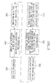
- Fig. 3 is a view structurally illustrating a method for improving an expansion performance of an air bag in accordance with the present invention
- Fig. 4 is a flowchart illustrating the method for improving an expansion performance of an air bag in accordance with the present invention
- Fig. 5 is a graph showing a result obtained when the method of the present invention is carried out.
- Fig. 6 is a graph showing another result obtained when the method of the present invention is carried out.
- Fig. 3 is a view structurally illustrating a method for improving an expansion performance of an air bag in accordance with the present invention.
- the air bag is expanded at a time close to the RTTF to the maximum when a vehicle collides, thereby minimizing damages of a driver and passengers, which are caused by a delayed expansion of the air bag.
- the deceleration detector detects a variation of the deceleration of the vehicle and applies the detected deceleration signal to a microcomputer (S10).
- the microcomputer analyzes the inputted collision waveform to determine the impact degree of the vehicle (S20). Then, while the collision waveform is increasing, the microcomputer temporarily stops the operation of the deceleration detector (S30). In a state that the operation of the deceleration detector is stopped, the microcomputer initializes an initial deceleration signal, which is recognized before the operation of the deceleration detector is stopped (S40).
- the microcomputer After a predetermined time elapses, the microcomputer re-operates the deceleration detector. Thus, the deceleration detector again detects a variation of the deceleration of the vehicle and applies the newly detected deceleration signal to the microcomputer (S50). The newly applied deceleration signal gradually increases in the waveform. At this time, if the collision waveform reaches a set value, the microcomputer operates an air bag driving unit of the air bag system to thereby expand the air bag (S60).
- the detecting operation of the deceleration detector is temporarily stopped after the vehicle collision, and the initially recognized collision waveform is initialized. Then, the deceleration detector re-operates and applies the newly detected deceleration signal to the microcomputer, thereby reducing the expansion time of the air bag. Accordingly, the expansion time of the air bag is closer to the RTTF, thereby achieving a more stable expansion performance of the air bag.
- Fig. 4 is a flowchart illustrating the method for improving the expansion performance of the air bag in accordance with the present invention.
- the method of the present invention will be described centrally about the steps shown in Fig. 3, i.e., the step (S20) of analyzing the collision waveform and determining the impact degree of the vehicle by the microcomputer, the step (S30) of stopping the operation of the deceleration detector, the step (S40) of initializing the initial deceleration signal, the step (50) of re-operating the deceleration detector to apply again the newly detected deceleration signal, and the step (S60) of expanding the air bag by the microcomputer.
- the microcomputer recognizes and analyzes the collision waveform according to the deceleration of the vehicle, which is applied from the deceleration detector (S100). After a predetermined time elapses from a moment when the microcomputer starts to recognize the initial collision waveform, the microcomputer determines whether or not the collision waveform reaches a set time range (S200). In that case, if an initial moment when the deceleration of the vehicle is detected by the deceleration detector is considered to be 0 ms, it is desirable that the set time range be set to a range of 20 ms to 30 ms.
- the detecting operation of the deceleration detector is stopped and the microcomputer initializes the initially recognized collision waveform (S300).
- the microcomputer re-operates the deceleration detector to restart the operation of detecting the deceleration of the vehicle according to the vehicle collision (S500).
- the microcomputer analyzes the collision waveform according to the variation of the deceleration applied from the deceleration detector and determines whether or not the collision waveform reaches the set value (S600).
- the microcomputer operates the air bag driving unit to expand the air bag (S700).
- Fig. 5 is a graph showing an exemplary application of the method in accordance with the present invention, which illustrates a result obtained when the method of the present invention is carried out in case that the vehicle collides head-on with a pillar at a speed of 19 mph among the above-described items.
- a minimum expansion time of the air bag is a point "E", i.e., 50 ms, and a maximum expansion time of the air bag is 53 ms.
- the expansion time of the air bag according to the present invention is much closer to the RTTF (50.2 ms).
- an undescirbed reference symbol "G” shows that the collision waveform decreases when the operation of the deceleration detector is stopped within the set time range of 20 ms to 30 ms.
- Fig. 6 is a graph showing another exemplary application of the method in accordance with the present invention, which illustrates a result obtained when the method of the present invention is carried out in case that the vehicle collides with a bus or a truck at a speed of 20 mph and is crushed under the bus or the truck.
- a minimum expansion time of the air bag is a point "F", i.e., 51 ms, and a maximum expansion time of the air bag is 53 ms.
- the expansion time of the air bag according to the present invention is much closer to the RTTF (48.7 ms).
- the air bag system of the present invention is very stable since there is almost no variation in the expansion time of the air bag.
- An undescirbed reference symbol "H" shows that the collision waveform decreases when the operation of the deceleration detector is stopped within the set time range of 20 ms to 30 ms.
- the detecting operation of the deceleration detector is temporarily stopped after the vehicle collision, and the initially recognized collision waveform is initialized. Then, the deceleration detector re-operates, thereby reducing the expansion time of the air bag. Accordingly, the expansion time of the air bag is closer to the RTTF, thereby achieving a more stable expansion performance of the air bag.
Landscapes
- Engineering & Computer Science (AREA)
- Mechanical Engineering (AREA)
- Physics & Mathematics (AREA)
- General Physics & Mathematics (AREA)
- Air Bags (AREA)
Abstract
Description
Claims (5)
- A method for improving an expansion performance of an air bag, the method comprising the steps of:whereby an expansion time of the air bag is reduced and close to a required time to fire (RTTF).(a) detecting a variation of deceleration of a vehicle in a vehicle collision at a deceleration detector and applying the detected deceleration signal to a microcomputer;(b) analyzing a collision waveform generated according to the deceleration signal and determining an impact degree of the vehicle at the microcomputer;(c) temporarily stopping operation of the deceleration detector at the microcomputer while the collision waveform is increasing;(d) initializing an initial collision waveform in a state that the operation of the deceleration detector is stopped, the initial collision waveform being inputted before the microcomputer stops the operation of the deceleration detector;(e) re-operating the deceleration detector at the microcomputer, detecting again a variation of the deceleration of the vehicle at the deceleration detector, and applying the newly detected deceleration signal to the microcomputer; and(f) when the collision waveform generated according to the applied deceleration signal reaches a set value, operating an air bag driving unit at the microcomputer to thereby expand the air bag,
- The method according to claim 1, wherein the step (b) further includes the step of determining whether or not the collision waveform reaches a set time range after a predetermined time elapses from a moment when the microcomputer starts to recognize the initial collision waveform.
- The method according to claim 1 or 2, wherein the step (c) is carried out when the collision waveform reaches the set time range after the microcomputer starts to recognize the collision waveform.
- The method according to claim 1, wherein the step (e) is carried out when the deceleration of the vehicle reaches 0 velocity digit.
- The method according to claim 2, wherein the set time range is 20 ms to 30 ms.
Applications Claiming Priority (2)
| Application Number | Priority Date | Filing Date | Title |
|---|---|---|---|
| KR10-2002-0027189A KR100435599B1 (en) | 2002-05-16 | 2002-05-16 | Method for improving air bag firing test |
| KR2002027189 | 2002-05-16 |
Publications (2)
| Publication Number | Publication Date |
|---|---|
| EP1362747A2 true EP1362747A2 (en) | 2003-11-19 |
| EP1362747A3 EP1362747A3 (en) | 2004-11-17 |
Family
ID=29267953
Family Applications (1)
| Application Number | Title | Priority Date | Filing Date |
|---|---|---|---|
| EP03004275A Withdrawn EP1362747A3 (en) | 2002-05-16 | 2003-02-26 | Method for improving expansion performance of air bag |
Country Status (5)
| Country | Link |
|---|---|
| US (1) | US7184870B2 (en) |
| EP (1) | EP1362747A3 (en) |
| JP (1) | JP2003335213A (en) |
| KR (1) | KR100435599B1 (en) |
| CN (1) | CN1458017A (en) |
Families Citing this family (2)
| Publication number | Priority date | Publication date | Assignee | Title |
|---|---|---|---|---|
| JP4258726B2 (en) * | 2004-02-20 | 2009-04-30 | 株式会社デンソー | Occupant protection system |
| KR101028368B1 (en) * | 2008-12-24 | 2011-04-11 | 주식회사 현대오토넷 | Airbag Control Device and Method |
Family Cites Families (15)
| Publication number | Priority date | Publication date | Assignee | Title |
|---|---|---|---|---|
| DE3606567A1 (en) * | 1986-02-28 | 1987-09-03 | Audi Ag | TEST METHOD FOR AIRBAG SYSTEM RELEASE CIRCUITS |
| WO1990011207A1 (en) * | 1989-03-20 | 1990-10-04 | Siemens Aktiengesellschaft | Control device for a passenger retaining and/or protective system for vehicles |
| JP2793084B2 (en) * | 1992-05-29 | 1998-09-03 | 三菱電機株式会社 | Starting device for occupant protection device |
| US5742916A (en) * | 1992-12-23 | 1998-04-21 | Siemens Aktiengesellschaft | Process and circuit for controlling the control unit of a system for protecting vehicle occupants |
| JP3324220B2 (en) * | 1993-09-07 | 2002-09-17 | 日産自動車株式会社 | Control device for occupant restraint system |
| US5366241A (en) * | 1993-09-30 | 1994-11-22 | Kithil Philip W | Automobile air bag system |
| US5394326A (en) * | 1994-01-24 | 1995-02-28 | Delco Electronics Corporation | Air bag deployment control system and method |
| US5668720A (en) * | 1994-04-28 | 1997-09-16 | Toyoda Gosei Co., Ltd. | Air bag controlling apparatus |
| KR100194360B1 (en) * | 1994-09-28 | 1999-06-15 | 전주범 | Testing apparatus of air bag and control method thereof |
| JPH0920205A (en) * | 1995-07-07 | 1997-01-21 | Mitsubishi Electric Corp | Occupant protection device and its activation device |
| US5936518A (en) * | 1995-10-31 | 1999-08-10 | Honda Giken Kogyo Kabushiki Kaisha | Method for judging vehicle collision |
| JP3546212B2 (en) * | 1997-11-11 | 2004-07-21 | オートリブ・ジャパン株式会社 | Airbag deployment control device |
| JP3482435B2 (en) * | 1998-03-31 | 2003-12-22 | オートリブ・ジャパン株式会社 | Airbag deployment control device |
| JP3436185B2 (en) * | 1999-02-09 | 2003-08-11 | トヨタ自動車株式会社 | Activation control device for occupant protection device |
| DE19913675B4 (en) * | 1999-03-25 | 2006-05-04 | Volkswagen Ag | Method and device for controlling a safety system in motor vehicles |
-
2002
- 2002-05-16 KR KR10-2002-0027189A patent/KR100435599B1/en not_active Expired - Fee Related
-
2003
- 2003-02-26 EP EP03004275A patent/EP1362747A3/en not_active Withdrawn
- 2003-02-28 JP JP2003054327A patent/JP2003335213A/en active Pending
- 2003-04-03 CN CN03108666A patent/CN1458017A/en active Pending
- 2003-05-16 US US10/440,210 patent/US7184870B2/en not_active Expired - Fee Related
Also Published As
| Publication number | Publication date |
|---|---|
| CN1458017A (en) | 2003-11-26 |
| EP1362747A3 (en) | 2004-11-17 |
| US20030214123A1 (en) | 2003-11-20 |
| KR20030089136A (en) | 2003-11-21 |
| JP2003335213A (en) | 2003-11-25 |
| US7184870B2 (en) | 2007-02-27 |
| KR100435599B1 (en) | 2004-06-09 |
Similar Documents
| Publication | Publication Date | Title |
|---|---|---|
| US8744690B2 (en) | Method for determining a criterion of the severity of an accident by means of an acceleration signal and a solid-borne sound signal | |
| US7416210B2 (en) | Method and device for controlling the triggering of passive safety system and the use thereof | |
| US6796397B2 (en) | Method of activating a passenger safety application in a motor vehicle | |
| US20030105569A1 (en) | Method for triggering means of restraint in a motor vehicle | |
| US20020134607A1 (en) | Method of impact detection for a motor vehicle | |
| JPH10512514A (en) | Vehicle airbag deployment control device and method | |
| US20040099462A1 (en) | Device for detecting a deformation of a structural component | |
| US6877357B2 (en) | Method of checking the functional reliability of a pressure sensor | |
| JP2007269279A (en) | Vehicle collision detection system | |
| KR100554853B1 (en) | Collision type identification device | |
| JP3632619B2 (en) | Occupant protection device starter | |
| AU2002334283A1 (en) | Collision Type Identifying Device | |
| EP1362747A2 (en) | Method for improving expansion performance of air bag | |
| JPH08324379A (en) | Vehicle side collision detection device | |
| EP1695875B1 (en) | Starting device of passenger protection apparatus | |
| JPH07251702A (en) | Method of operating vehicle occupant protecting device | |
| CN118478823B (en) | Vehicle side collision protection method, vehicle-mounted controller, system, storage medium and vehicle | |
| JP4351378B2 (en) | Obstacle estimation device for vehicle | |
| CN101031457A (en) | Method and device for triggering a personal protection mechanism | |
| JPH0924795A (en) | Side collision discrimation device for vehicle | |
| JP2002062308A (en) | Collision type determination device | |
| US20050004729A1 (en) | Roll angle plausibility detection | |
| JPH04146851A (en) | Passenger protection device for vehicle | |
| KR100437245B1 (en) | A Frontal Airbag System of Vehicle and Control Method thereof | |
| KR20050031179A (en) | Bumper air-bag control method |
Legal Events
| Date | Code | Title | Description |
|---|---|---|---|
| PUAI | Public reference made under article 153(3) epc to a published international application that has entered the european phase |
Free format text: ORIGINAL CODE: 0009012 |
|
| AK | Designated contracting states |
Kind code of ref document: A2 Designated state(s): AT BE BG CH CY CZ DE DK EE ES FI FR GB GR HU IE IT LI LU MC NL PT SE SI SK TR |
|
| AX | Request for extension of the european patent |
Extension state: AL LT LV MK RO |
|
| RIN1 | Information on inventor provided before grant (corrected) |
Inventor name: KIM, HOON,521-1603 JUKONG-GAYA APARTMENT |
|
| PUAL | Search report despatched |
Free format text: ORIGINAL CODE: 0009013 |
|
| AK | Designated contracting states |
Kind code of ref document: A3 Designated state(s): AT BE BG CH CY CZ DE DK EE ES FI FR GB GR HU IE IT LI LU MC NL PT SE SI SK TR |
|
| AX | Request for extension of the european patent |
Extension state: AL LT LV MK RO |
|
| AKX | Designation fees paid | ||
| REG | Reference to a national code |
Ref country code: DE Ref legal event code: 8566 |
|
| STAA | Information on the status of an ep patent application or granted ep patent |
Free format text: STATUS: THE APPLICATION IS DEEMED TO BE WITHDRAWN |
|
| 18D | Application deemed to be withdrawn |
Effective date: 20050518 |