EP1362665A1 - An anthropomorphic head for machine tools with an operating unit with reduced radial dimension - Google Patents
An anthropomorphic head for machine tools with an operating unit with reduced radial dimension Download PDFInfo
- Publication number
- EP1362665A1 EP1362665A1 EP03425302A EP03425302A EP1362665A1 EP 1362665 A1 EP1362665 A1 EP 1362665A1 EP 03425302 A EP03425302 A EP 03425302A EP 03425302 A EP03425302 A EP 03425302A EP 1362665 A1 EP1362665 A1 EP 1362665A1
- Authority
- EP
- European Patent Office
- Prior art keywords
- axis
- shaft
- rotation
- operating
- tool
- Prior art date
- Legal status (The legal status is an assumption and is not a legal conclusion. Google has not performed a legal analysis and makes no representation as to the accuracy of the status listed.)
- Granted
Links
- 238000003754 machining Methods 0.000 claims abstract description 35
- 230000033001 locomotion Effects 0.000 claims description 18
- 230000005540 biological transmission Effects 0.000 claims description 5
- 239000002023 wood Substances 0.000 claims description 2
- 239000000463 material Substances 0.000 claims 1
- 238000004804 winding Methods 0.000 abstract description 2
- 210000003414 extremity Anatomy 0.000 description 40
- 125000006850 spacer group Chemical group 0.000 description 5
- 238000010276 construction Methods 0.000 description 4
- 238000005520 cutting process Methods 0.000 description 4
- 238000004519 manufacturing process Methods 0.000 description 4
- 238000000034 method Methods 0.000 description 3
- 238000013519 translation Methods 0.000 description 3
- 210000000707 wrist Anatomy 0.000 description 3
- 230000008901 benefit Effects 0.000 description 2
- 238000009826 distribution Methods 0.000 description 2
- 238000013459 approach Methods 0.000 description 1
- 230000008859 change Effects 0.000 description 1
- 239000000428 dust Substances 0.000 description 1
- 238000004870 electrical engineering Methods 0.000 description 1
- 230000003993 interaction Effects 0.000 description 1
- 238000012423 maintenance Methods 0.000 description 1
- 238000005259 measurement Methods 0.000 description 1
- 230000007246 mechanism Effects 0.000 description 1
- 238000012986 modification Methods 0.000 description 1
- 230000004048 modification Effects 0.000 description 1
- 230000000284 resting effect Effects 0.000 description 1
- 238000005096 rolling process Methods 0.000 description 1
- 210000003857 wrist joint Anatomy 0.000 description 1
Images


Classifications
-
- B—PERFORMING OPERATIONS; TRANSPORTING
- B27—WORKING OR PRESERVING WOOD OR SIMILAR MATERIAL; NAILING OR STAPLING MACHINES IN GENERAL
- B27C—PLANING, DRILLING, MILLING, TURNING OR UNIVERSAL MACHINES FOR WOOD OR SIMILAR MATERIAL
- B27C3/00—Drilling machines or drilling devices; Equipment therefor
- B27C3/06—Drilling machines or devices for making dowel holes
-
- B—PERFORMING OPERATIONS; TRANSPORTING
- B23—MACHINE TOOLS; METAL-WORKING NOT OTHERWISE PROVIDED FOR
- B23Q—DETAILS, COMPONENTS, OR ACCESSORIES FOR MACHINE TOOLS, e.g. ARRANGEMENTS FOR COPYING OR CONTROLLING; MACHINE TOOLS IN GENERAL CHARACTERISED BY THE CONSTRUCTION OF PARTICULAR DETAILS OR COMPONENTS; COMBINATIONS OR ASSOCIATIONS OF METAL-WORKING MACHINES, NOT DIRECTED TO A PARTICULAR RESULT
- B23Q1/00—Members which are comprised in the general build-up of a form of machine, particularly relatively large fixed members
- B23Q1/25—Movable or adjustable work or tool supports
- B23Q1/44—Movable or adjustable work or tool supports using particular mechanisms
- B23Q1/50—Movable or adjustable work or tool supports using particular mechanisms with rotating pairs only, the rotating pairs being the first two elements of the mechanism
- B23Q1/54—Movable or adjustable work or tool supports using particular mechanisms with rotating pairs only, the rotating pairs being the first two elements of the mechanism two rotating pairs only
-
- B—PERFORMING OPERATIONS; TRANSPORTING
- B23—MACHINE TOOLS; METAL-WORKING NOT OTHERWISE PROVIDED FOR
- B23Q—DETAILS, COMPONENTS, OR ACCESSORIES FOR MACHINE TOOLS, e.g. ARRANGEMENTS FOR COPYING OR CONTROLLING; MACHINE TOOLS IN GENERAL CHARACTERISED BY THE CONSTRUCTION OF PARTICULAR DETAILS OR COMPONENTS; COMBINATIONS OR ASSOCIATIONS OF METAL-WORKING MACHINES, NOT DIRECTED TO A PARTICULAR RESULT
- B23Q1/00—Members which are comprised in the general build-up of a form of machine, particularly relatively large fixed members
- B23Q1/70—Stationary or movable members for carrying working-spindles for attachment of tools or work
-
- B—PERFORMING OPERATIONS; TRANSPORTING
- B23—MACHINE TOOLS; METAL-WORKING NOT OTHERWISE PROVIDED FOR
- B23Q—DETAILS, COMPONENTS, OR ACCESSORIES FOR MACHINE TOOLS, e.g. ARRANGEMENTS FOR COPYING OR CONTROLLING; MACHINE TOOLS IN GENERAL CHARACTERISED BY THE CONSTRUCTION OF PARTICULAR DETAILS OR COMPONENTS; COMBINATIONS OR ASSOCIATIONS OF METAL-WORKING MACHINES, NOT DIRECTED TO A PARTICULAR RESULT
- B23Q5/00—Driving or feeding mechanisms; Control arrangements therefor
- B23Q5/02—Driving main working members
- B23Q5/04—Driving main working members rotary shafts, e.g. working-spindles
- B23Q5/043—Accessories for spindle drives
- B23Q5/046—Offset spindle drives
-
- B—PERFORMING OPERATIONS; TRANSPORTING
- B23—MACHINE TOOLS; METAL-WORKING NOT OTHERWISE PROVIDED FOR
- B23Q—DETAILS, COMPONENTS, OR ACCESSORIES FOR MACHINE TOOLS, e.g. ARRANGEMENTS FOR COPYING OR CONTROLLING; MACHINE TOOLS IN GENERAL CHARACTERISED BY THE CONSTRUCTION OF PARTICULAR DETAILS OR COMPONENTS; COMBINATIONS OR ASSOCIATIONS OF METAL-WORKING MACHINES, NOT DIRECTED TO A PARTICULAR RESULT
- B23Q2220/00—Machine tool components
- B23Q2220/006—Spindle heads
Definitions
- the present invention relates to a jointed head, of the type also known by the name anthropomorphic head, designed for application on machine tools for woodworking, in particular on machining centres for routing and boring wooden panels or workpieces, with a tool which can be positioned on two or more machining axes.
- Such machines are well known in the sector of secondary machining of wood and similar products, in particular for the production of furniture.
- the routing performed on said machines is needed to obtain the finished parts from wooden workpieces, normally in the form of a panel, which are routed both on their edges, to obtain a border with various shapes, and sometimes on other parts of their surfaces, to mould them, that is to say, to obtain cavities and bored holes angled according to various axes.
- Typical applications for these machining operations are found, for example, in the production of moulded doors for high quality kitchen furniture.
- a problem to be solved - relative to the solutions currently existing, and to the disadvantages inherent in them - is not just the problem of assigning all necessary degrees of freedom to the tool, but - at the same time - the technical problem of optimising tool accessibility on the workpiece, simultaneously maintaining the considerable compactness of the solution used.
- Prior art in the sector of such anthropomorphic heads for machining centres refers to heads substantially with a kinematic chain configuration which, by means of limbs arranged in succession and jointed by means of rotary pairs or ball joints, can position the tool at the required co-ordinates, obviously within a given range of permitted mobility.
- such anthropomorphic heads consist of a set of joints or "wrists" (making them anthropomorphic) which connect the succession of limbs forming the kinematic chain for tool positioning, that also give it the necessary rotational degrees of freedom, required to angle its axis according to the different possible directions.
- the desired translation movements in the three directions - which are obviously omitted in the descriptions that follow-are obtained by moving a limb located at the origin of such heads, slidably connected on a mobile machine element, which normally coincides with the mobile upright above the machine worktable.
- the cutting rotation of the tool is driven either by a shaft transmission and relative circular and/or bevel connecting gears, which pass inside the limbs to transmit the cutting rotary motion from the origin of the chain to the tool at the end of the chain (where gears or joints are substantially arranged in the wrists of the chain), or tool cutting rotation is driven by a customary electrospindle at the end of the chain which transmits the cutting rotation directly to the tool.
- First solutions of such jointed heads include the possibility of angling the tool axis in all directions of a vertical plane "p" constantly perpendicular to the machine worktable (horizontal), by means of a circular star support with two or more tools arranged radially on the star, in turn contained in the plane "p".
- a first rotary joint with vertical axis (U1) angled a first limb on which the star was rotatably supported about a horizontal axis (U2) passing through its centre and perpendicular to its plane "p”. Things were also usually arranged so that the vertical axis (U1) also passed through the centre of the star, where a system of shafts inside the limbs of the chain transmitted the rotary motion to the tools.
- the tool axis (U3) could be turned from a vertical direction to a horizontal direction, by simply turning the electrospindle about the axis (U2), where all of the horizontal directions were made possible for the axis (U3) by simply turning the first limb about the axis (U1).
- the tool holder star could easily perform boring and routing on a workpiece fixed directly to the machine worktable, if and only if the machining required the tool to be positioned vertically. If the boring had to be carried out on the middle plane of a panel, with the tool axis positioned horizontally, obviously due to interference between the star and the table, the workpiece being machined could not rest directly on the machine worktable, but required special spacer supports, of the known type, to distance the panel from the worktable, at least by a measurement equal to the radius of the star. Therefore, heads made according to the first solutions had the serious disadvantage of requiring that the workpiece be placed on said spacers rather than directly on the machine worktable.
- jointed head architectures described in the prior art do not in themselves contain elements useful for simultaneously solving both the problem of assigning the tool the necessary degrees of freedom, and the problem of extensive and unconditional access to all lateral parts of a workpiece fixed directly to the machine worktable, therefore, for machining operations with the tool axis parallel with the machine worktable and for reduced Hmin heights relative to the worktable, necessary for correct operation of the axis.
- the aim of the jointed head disclosed in the present invention is to overcome the above-mentioned disadvantages. Accordingly the present invention, as described in the claims herein, solves the problem of producing a device in the form of an anthropomorphic jointed head for supporting a tool for routing/boring on machining centres. Basically this device does not have the problem of an excessive minimum machining height Hmin allowed, which would necessitate spacer accessories for fixing workpieces to the machine worktable.
- the device in the form of a head must simultaneously have extremely simple construction and versatile operation, and it must retain all of the positive functional characteristics of previous solutions, or better still, improve on them.
- the idea developed hereinafter achieves the preset aims with a head configuration of the above-mentioned type, to be attached to the crosspiece (normally mobile) above the machine worktable designed for fixing the workpieces to be machined on the machining centre.
- a jointed machining head for a machine tool which machines wooden workpieces on a machine worktable, configured as a kinematic chain with at least one first joint R1 able to rotate about at least one joint geometrical axis W1.
- the head comprises a compact motor-driven unit which drives the rapid rotation of a routing tool about an axis identified in said unit, and where the unit can be positioned by the kinematic chain at least in an operating position in which the axis of tool rapid rotation is parallel with the machine worktable.
- the compact motor-driven unit comprises, within a shaft support casing, a first driving part, consisting of an electric motor whose rotor is a first, driving shaft, with a first axis of rotation 7a identified in the unit; and a second, operating part, consisting of a second, operating shaft, having a second axis of rotation 8a identified in the unit, parallel with and close to the previous driving axis 7a, and with an operating end 8e designed to provide coaxial support for the tool operating outside the casing, so that the tool takes the second axis of rotation 8a as its own axis of rapid rotation.
- the second shaft is rotationally driven by the first, driving shaft by means for transmitting rotational motion.
- the casing is advantageously made with a much reduced dimension along the radial half-lines s originating from the second axis of rotation 8a and moving away from the first axis of rotation 7a, so that in the one or more operating positions where the tool axis is parallel with the machine worktable, the radial distance between the second, operating shaft and the machine worktable, and each workpiece being machined is very small.
- the transmission elements acting between the shafts and the driving and operating parts are also specified, in the form of a toothed belt and relative pulleys at the non-operating end of the driven shaft.
- the presence of means designed to lock and release the tool is specified, although the claims only cover their positioning and compatibility with the architecture of the motor-driven unit described above, since their other aspects are substantially known.
- the structure of the kinematic chain over the unit is also specified, configuring the head as a whole.
- the positions of the joint axes of the anthropomorphic head are specified.
- the geometrical axis W1 of the joint R1 may be perpendicular to the machine worktable, whilst the axis 8a of the operating shaft may be parallel with the worktable.
- the kinematic chain forming the head may have at least one additional joint R2 with an axis of rotation W2, where the axes W1 and W2 would be incident with one another at a point C at least for a set of head positions.
- the first joint R1 would allow rotation of the axis W2 about the axis W1 according to a cone with vertex C and half-opening equal to 45°
- the second joint R2 would allow rotation of the axis 8a about the axis W2 according to a cone with vertex C and half-opening equal to 45°, so that in the particular case in which the axis W1 is perpendicular to the machine worktable, the tool axis of rotation 8a could occupy - by means of 180° swinging about the axis W2- both an operating position parallel with the machine worktable, and an operating position perpendicular to the worktable, and coinciding with the axis W1.
- the architecture of a head made according to the present invention does not require any compensating stroke (as seen above) to pass from vertical to horizontal routing/boring, and above all the minimum machining height Hmin allowed for the tool on the horizontal axis is significantly lower than all of the architectures previously known in the prior art, where this may be attributed to the particular structural configuration of the invention, in which the radial dimension of the stator and rotor electric packs has been completely removed to the driving shaft, which has been separated from the operating shaft, so that around the latter there are only the dimensions of the elements needed to support rotation of the operating shaft, providing the minimum dimensions necessary.
- This device in the form of a jointed machining head 1, particularly innovative as regards the solution relating to the compact motor-driven operating unit proposed, and at the same time very simple, basically comprises a kinematic chain with substantially known layout, consisting of three limbs 15, 16, 17, jointed to one another in succession, to form an arm, by two wrist joints R1 and R2, where each of the wrists is - from the connecting viewpoint - a rotary joint with axis of rotation W1 or W2.
- the joint R1 is located between the limbs 15 and 16, and the joint R2 is between the limbs 16 and 17, where the limb 17, immediately downstream of the joint R2, has a special casing 6 structure, forming the outer cover of the compact motor-driven unit 3 which supports and drives the tool 4, and designed to enclose its mechanisms.
- the head limb 15 is, in turn, slidably supported by a machine slide 18, inserted between the head limb 15 and the machine upright 19, which is mobile along its X axis.
- the slide 18 in turn has both guides 18g on one of its faces, angled according to the Z axis and on which the limb 15 can slide vertically, and counter-guides on its other face, designed to allow the slide 18 to slide on the guides 19g on the upright, angled according to the direction Y. Therefore, the slide 18 is a type of cross-shaped slide which, combined with the mobility of the upright 19 in direction X, guarantees the three degrees of freedom in head translation X, Y, Z.
- joints R1 and R2 like the other movements, are motor-driven and controlled according to the usual solutions (which are, therefore, not described in further detail), designed to allow the desired positioning of the head 1 limbs in predetermined successive configurations, and in particular to angle the tool axis according to any direction.
- the joint R1 by which the limb 15 supports the next limb 16, is positioned in such a way that its axis of rotation W1 is perpendicular to the machine worktable 5, designed for fixing the workpieces 2, and therefore angled like the machine Z axis.
- the subsequent joint R2 by which the limb 16 supports the next limb 17, is positioned in such a way that its axis of rotation W2 is incident with the previous axis W1 at a point C on it, and so that the axis W2 is set at 45° to the axis W1.
- the axis W2 is also set at 45° to the machine worktable 5 and, thanks to the joint R1, the axis W2 can describe the lateral surface of a cone with vertex C and axis W1, having half-opening equal to 45°.
- rotation of the limb 16 on the limb 15 induces rotation of the axis W2 about the vertical axis W1 according to the aforementioned method.
- limb 17 Immediately downstream of the joint R2, and rotatably connected by it to the previous limb 16, is the limb 17, as indicated above.
- the part of the limb 17 adjacent to the joint R2 has a flat connecting surface to which the casing 6 is attached by threaded connections.
- the casing delimits the compact motor-driven unit 3 which supports and drives the tool 4, considered part of the third limb 17.
- the unit 3 casing 6 is particularly suitable for housing two parallel shafts 7 and 8, rotating relative to the casing 6 about respective geometrical axes 7a and 8a identified in it by means of suitable bearing seats, where, of the two, the shaft 8 is designed to support the routing/boring tool, as indicated in further detail below.
- connection between the casing 6 and the flat surface of the limb 17 is, during construction, made such that the plane identified by the two parallel axes 7a and 8a also contains the axis W2 of the limb 17, where the angle according to which the parallel axes 7a and 8a cut the axis W2 is equal to 45°.
- Another important head 1 characteristic derives from the correct provision of the method used to connect the limb 17 to the limb 16. That is to say, the characteristic by which the point at which the axes 8a and W2 meet coincides with the point C previously defined as the intersection of axes W1 and W2, where in particular this property is achieved by correctly setting the axial distance between the ring nuts of the joint R2.
- the casing 6 is delimited by the casing 6, and is substantially separated into two parts, of which one is a driving part, extending around a geometrical axis 7a, and one is an operating part, driving the tool and extending around a geometrical axis 8a.
- the axes 7a and 8a are identified in the casing 6 by relative bearing seats and are parallel with one another.
- the driving part has an electric motor whose rotor is a shaft 7 with geometrical axis 7a, supported by the casing 6 by means of rolling bearings, and which has a conventional electric pack consisting of a rotor which in turn - with an air gap - turns in a conventional electric pack consisting of stator windings, according to customary electrical engineering solutions.
- the casing At one end of the shaft 7 - which may be called the front relative to the front of the operating unit 3 - the casing has a secondary service cover 20, for maintenance or substituting the front supporting bearing, whilst at the opposite end - which may be called the back - the shaft 7 has a toothed pulley 7p for a toothed belt 10, and is supported by a rear bearing.
- the casing 6 also has end plates 21 and 22 housing the roller bearings, the end plates being removable from the casing 6, to give it the modularity which allows the assembly/disassembly of internal parts, according to the solutions applied in the shaft casings.
- the upper part of Figure 2 illustrates both the secondary service cover 20, and the removable end plate 21 of the casing 6, designed to support the bearing on the front end of the shaft 7.
- the end plate 22 which is the seat of the shaft 7 rear bearing, is inside the casing 6.
- Said operating part is separated from the driving part by an incomplete ridge 29, which also has structural functions for the casing 6, and identifies a compartment in the casing 6 which, with reference to a horizontal shaft 7 position, is below the compartment where the driving part is located.
- An axially hollow shaft 8, with geometrical axis 8a and supported by roller bearings in the lower part of the casing 6, is the basic element of the operating part.
- a toothed pulley 8p is keyed, suitable for engaging with the toothed belt 10, and for using the belt to receive the motion generated by the driving shaft 7.
- the casing has an opening for shaft 8 output, with a cover 28 that also has an opening, partly designed to retain bearings located at the operating end 8e.
- Figure 2 provides a front view of the fastening screws and the edge of the cover 28.
- the radial dimension necessary to support the operating shaft 8 is noticeably reduced compared with that required for the driving shaft 7, which must be surrounded not only by the bearings, but also by the rotor and stator electric packs.
- the shaft 8 has an axial through cavity, terminating at the operating end 8e in a cone-shaped seat, and suitable for receiving standard taper shanks, for example, of the HSK type in accordance with DIN standards.
- the axial cavity houses part 11b of the set of systems 11 usually used to lock/release the holder of the tool 4, that is to say, a control rod, a pack of Belleville washers surrounding the rod, and the tool holder expanding collet, some of these elements only partially illustrated in the accompanying drawings, or not at all in the cavity, since they refer to prior art.
- the part 11b of the set of locking/release systems 11 housed in the shaft cavity is driven by an actuator part 11a for the set of systems 11.
- the actuator part 11a consists of a shaped plate 23, connected on one side to the end plate 22 and to other elements of the casing 6, whilst the other side forms the body of a pneumatic cylinder with geometrical axis 7a, having a cylindrical cavity for a large-diameter piston 24 driven by compressed air, which slides along the axis 7a.
- a cover 26 acts as the base for both the body of the pneumatic cylinder and the unit 3 casing 6, and also has a fulcrum for a rocker arm 25, which transfers the piston 24 stroke to the tool release control rod.
- the air arriving from the distribution network flows to/from the two chambers in the cylinder through special holes, and using customary pneumatic distribution components, controlled by a control device.
- a light service cover 27 is located at the very back of the casing 6, protecting the rocker arm from dust. There is a hole at the shaft 8 axis 8a, that is to say, the shaft which slides inside it.
- the actuator part 11a of the locking/release means 11 may be connected to a head 1 limb 11m, separated from the unit 3, both to make the unit 3 lighter and to avoid the presence of relative tubes for pressurised air arriving as far as the unit 3, for controlling the pneumatic cylinder.
- the tool is only unlocked with the head 1 in a kinematic chain configuration in which the parts 11a and 11b are adjacent, so that the active limb of the part 11a can act upon the control rod by means of the passage represented by the hole in the light cover 27.
- the device structured in this way in the form of a head 1 with a motor-driven tool drive unit 3, fulfils the preset aims thanks to the mutual arrangements of the various elements illustrated, without having to change the remaining machine structure which already exists.
- the geometrical axes W1, W2 and 8a converge at point C where - thanks to rotation of the limb 16 on the joint R1 - the axis W2 can describe a conical surface with vertex C, with axis W1 and half-opening equal to 45°, whilst - thanks to rotation of the limb 17 on the joint R2 - the axis 8a can describe a conical surface with vertex C, with axis W2 and half-opening equal to 45°.
- the two types of rotation - about W2 and about W1-can demonstrate how the tool axis 8a can be angled according to any of the straight lines belonging to the star with point C as the support, and in particular - as illustrated in Figure 1 - it can assume all directions in the horizontal plane, that is to say, parallel with the worktable 5, and the vertical direction coinciding with the axis W1, that is to say, perpendicular to the worktable 5.
- the direction identified by the tip of the tool always has a component facing the worktable 5, which may be null at most.
- the position of the tool 4 axis 8a is identified by the point C and by any other point Q of the axis 8a, where the motion of the point Q-by construction - must occur on a spherical surface with centre C and radius CQ, designed to represent a movement by a rigid body with a fixed point.
- the joints R1 and R2 (or rather on their ring nuts) there is a fixed origin of the respective angles of rotation and a measuring scale for them.
- the angles measured on such R1 and R2 scales form a pair of parameters necessary and sufficient for identifying the geometrical configuration of the head 1, that is to say, for defining the position of the tool axis, where - starting for example from the respective origins on the graduated scales-the order with which rotations on the two joints are attributed has no influence, since the two axes are not absolutely fixed in space (as this would prevent switching of the composition of the finished rotations), but the second axis W2 is rotated by the first axis W1.
- the two rotations measured on the joints R1 and R2 constitute two parameters, known as Lagrangians, which unambiguously identify the system configuration, where, as is known, said configuration does not depend on the order with which such parameters are assigned.
- the operation of the tool release device is easily explainable by observing that, while the piston 24 performs an active release stroke, towards the back of the casing 6, the relative rod activates the rocker arm 25, which acts upon the release rod contained in the shaft cavity, where the rod return stroke - and that of the piston 24 - is directly controlled by the elastic reaction of the Belleville washers acting between the shaft 8 and the rod.
Landscapes
- Engineering & Computer Science (AREA)
- Mechanical Engineering (AREA)
- Life Sciences & Earth Sciences (AREA)
- Wood Science & Technology (AREA)
- Forests & Forestry (AREA)
- Machine Tool Units (AREA)
- Drilling And Boring (AREA)
- Baking, Grill, Roasting (AREA)
- Soil Working Implements (AREA)
- Shovels (AREA)
Abstract
Description
- The present invention relates to a jointed head, of the type also known by the name anthropomorphic head, designed for application on machine tools for woodworking, in particular on machining centres for routing and boring wooden panels or workpieces, with a tool which can be positioned on two or more machining axes.
- Such machines are well known in the sector of secondary machining of wood and similar products, in particular for the production of furniture. The routing performed on said machines is needed to obtain the finished parts from wooden workpieces, normally in the form of a panel, which are routed both on their edges, to obtain a border with various shapes, and sometimes on other parts of their surfaces, to mould them, that is to say, to obtain cavities and bored holes angled according to various axes.
- Typical applications for these machining operations are found, for example, in the production of moulded doors for high quality kitchen furniture.
- In the above-mentioned machining centres the workpieces are normally positioned on a machine worktable, and fixed there with known systems, so that the required routing and boring can be started.
- On such machines it is, therefore, necessary to allow the routing tool to reach the greatest possible number of positions on the workpiece, depending on the workpiece resting and fixing constraints. This is determined by the greater or lesser reciprocal mobility on the machine between the tool supporting head and the machine worktable where, in the most common cases, the worktable is fixed and the tool holder head is allowed all degrees of freedom.
- A problem to be solved - relative to the solutions currently existing, and to the disadvantages inherent in them - is not just the problem of assigning all necessary degrees of freedom to the tool, but - at the same time - the technical problem of optimising tool accessibility on the workpiece, simultaneously maintaining the considerable compactness of the solution used.
- Prior art in the sector of such anthropomorphic heads for machining centres refers to heads substantially with a kinematic chain configuration which, by means of limbs arranged in succession and jointed by means of rotary pairs or ball joints, can position the tool at the required co-ordinates, obviously within a given range of permitted mobility.
- Basically, such anthropomorphic heads consist of a set of joints or "wrists" (making them anthropomorphic) which connect the succession of limbs forming the kinematic chain for tool positioning, that also give it the necessary rotational degrees of freedom, required to angle its axis according to the different possible directions. In contrast, the desired translation movements in the three directions - which are obviously omitted in the descriptions that follow-are obtained by moving a limb located at the origin of such heads, slidably connected on a mobile machine element, which normally coincides with the mobile upright above the machine worktable.
- At the end of the kinematic chain, the cutting rotation of the tool is driven either by a shaft transmission and relative circular and/or bevel connecting gears, which pass inside the limbs to transmit the cutting rotary motion from the origin of the chain to the tool at the end of the chain (where gears or joints are substantially arranged in the wrists of the chain), or tool cutting rotation is driven by a customary electrospindle at the end of the chain which transmits the cutting rotation directly to the tool.
- First solutions of such jointed heads, developed by various manufacturers, include the possibility of angling the tool axis in all directions of a vertical plane "p" constantly perpendicular to the machine worktable (horizontal), by means of a circular star support with two or more tools arranged radially on the star, in turn contained in the plane "p". In these solutions a first rotary joint with vertical axis (U1) angled a first limb on which the star was rotatably supported about a horizontal axis (U2) passing through its centre and perpendicular to its plane "p". Things were also usually arranged so that the vertical axis (U1) also passed through the centre of the star, where a system of shafts inside the limbs of the chain transmitted the rotary motion to the tools.
- In jointed heads developed according to these solutions, for example, by the Italian company CTC, the kinematic chain was more sophisticated and versatile than previously, with a first limb which rotated about a first vertical axis (U1), perpendicular to the machine worktable, in turn having a rotary joint whose axis (U2) was incident with a point C and was angled at 45° to the previous axis (U1). On this rotary joint with axis (U2) there turned - relative to the first limb-the body of a normal electrospindle, whose tool axis (U3) was arranged incident with the previous two axes (U1) and (U2) at point C common to both, and was set at 45° degrees to the axis (U2). In this way, the tool axis (U3) could be turned from a vertical direction to a horizontal direction, by simply turning the electrospindle about the axis (U2), where all of the horizontal directions were made possible for the axis (U3) by simply turning the first limb about the axis (U1).
- A similar solution was achieved by substituting the 45° angle in the above description with a 90° angle, so that the axes U1 and U2 were at a right angle to one another, and the tool axis U3 could describe the plane perpendicular to the axis U2 and passing through point C.
- The above-mentioned solutions for production of the jointed heads on one hand solved the problem of allowing the tool the necessary degrees of freedom quite satisfactorily but, on the other hand, had the disadvantage of not allowing satisfactory tool accessibility to all parts of a workpiece fixed directly to the machine worktable, particularly with reference to machining to be performed on the lateral edge of the workpiece, for example, boring with a horizontal axis in the workpiece middle plane. This applied above all in terms of interference between the head - or the part of it designed to support the tool - and the machine worktable.
- The disadvantages described are easily deducible from the previous qualitative descriptions.
- With reference to the first solutions mentioned, it is understandable how the tool holder star could easily perform boring and routing on a workpiece fixed directly to the machine worktable, if and only if the machining required the tool to be positioned vertically. If the boring had to be carried out on the middle plane of a panel, with the tool axis positioned horizontally, obviously due to interference between the star and the table, the workpiece being machined could not rest directly on the machine worktable, but required special spacer supports, of the known type, to distance the panel from the worktable, at least by a measurement equal to the radius of the star. Therefore, heads made according to the first solutions had the serious disadvantage of requiring that the workpiece be placed on said spacers rather than directly on the machine worktable. Moreover, such positioning in itself brought the secondary disadvantage of having to assign the head the movement strokes in the direction Z perpendicular to the machine worktable, designed to compensate for the different machining height (comparable to the star radius) when passing between a boring/routing operation with a horizontal axis (star in raised position) and an operation with a vertical axis (star in lowered position), and vice versa.
- To summarise, the above-mentioned first solutions, were limited by the "minimum machining height Hmin allowed" parameter of the horizontal tool relative to the machine worktable, a parameter which depended on the radius of the star.
- With reference to the second solutions, the limitation imposed by the minimum machining height Hmin allowed relative to the machine worktable also existed, although for different reasons.
- Considering the second solutions of heads in the machining position with the tool axis parallel with the machine worktable (horizontal), it was the radial dimension of the electrospindle electric motor's rotor and stator pack that formed the obstacle which meant that the radial distance of the spindle shaft relative to the machine worktable had to remain greater than or equal to that value Hmin, basically comparable to the radial dimension of the electric pack. Where, due to considerable spindle powers (from approximately 10 kW upwards), its radial dimension became very considerable, not even the flattening often made under it - that is to say, opposite the fitting with its supporting kinematic chain - could be of any significant benefit regarding the possibility of radial proxmity between the spindle and the machine worktable. So, the second solutions also required the use of spacer supports for positioning workpieces, although without the disadvantage of having to perform compensating strokes when the tool axis passed from vertical to horizontal, characteristic of the first solutions.
- The above indicates how the jointed head architectures described in the prior art, like other functionally equivalent architectures, do not in themselves contain elements useful for simultaneously solving both the problem of assigning the tool the necessary degrees of freedom, and the problem of extensive and unconditional access to all lateral parts of a workpiece fixed directly to the machine worktable, therefore, for machining operations with the tool axis parallel with the machine worktable and for reduced Hmin heights relative to the worktable, necessary for correct operation of the axis.
- The aim of the jointed head disclosed in the present invention is to overcome the above-mentioned disadvantages. Accordingly the present invention, as described in the claims herein, solves the problem of producing a device in the form of an anthropomorphic jointed head for supporting a tool for routing/boring on machining centres. Basically this device does not have the problem of an excessive minimum machining height Hmin allowed, which would necessitate spacer accessories for fixing workpieces to the machine worktable. The device in the form of a head must simultaneously have extremely simple construction and versatile operation, and it must retain all of the positive functional characteristics of previous solutions, or better still, improve on them.
- The idea developed hereinafter achieves the preset aims with a head configuration of the above-mentioned type, to be attached to the crosspiece (normally mobile) above the machine worktable designed for fixing the workpieces to be machined on the machining centre.
- More precisely, it is a jointed machining head, for a machine tool which machines wooden workpieces on a machine worktable, configured as a kinematic chain with at least one first joint R1 able to rotate about at least one joint geometrical axis W1. The head comprises a compact motor-driven unit which drives the rapid rotation of a routing tool about an axis identified in said unit, and where the unit can be positioned by the kinematic chain at least in an operating position in which the axis of tool rapid rotation is parallel with the machine worktable.
- The special feature of this head is the fact that the compact motor-driven unit comprises, within a shaft support casing, a first driving part, consisting of an electric motor whose rotor is a first, driving shaft, with a first axis of
rotation 7a identified in the unit; and a second, operating part, consisting of a second, operating shaft, having a second axis ofrotation 8a identified in the unit, parallel with and close to theprevious driving axis 7a, and with an operatingend 8e designed to provide coaxial support for the tool operating outside the casing, so that the tool takes the second axis ofrotation 8a as its own axis of rapid rotation. The second shaft is rotationally driven by the first, driving shaft by means for transmitting rotational motion. - In such a solution, due to the absence of the electric pack on the second shaft, the casing is advantageously made with a much reduced dimension along the radial half-lines s originating from the second axis of
rotation 8a and moving away from the first axis ofrotation 7a, so that in the one or more operating positions where the tool axis is parallel with the machine worktable, the radial distance between the second, operating shaft and the machine worktable, and each workpiece being machined is very small. - With this special layout of the elements in the invention, the transmission elements acting between the shafts and the driving and operating parts are also specified, in the form of a toothed belt and relative pulleys at the non-operating end of the driven shaft. In addition, the presence of means designed to lock and release the tool is specified, although the claims only cover their positioning and compatibility with the architecture of the motor-driven unit described above, since their other aspects are substantially known.
- Moreover, again depending on the special layout of the elements in the invention, the structure of the kinematic chain over the unit is also specified, configuring the head as a whole. In the case in question the positions of the joint axes of the anthropomorphic head are specified. In particular, the geometrical axis W1 of the joint R1 may be perpendicular to the machine worktable, whilst the
axis 8a of the operating shaft may be parallel with the worktable. - Moreover, the kinematic chain forming the head may have at least one additional joint R2 with an axis of rotation W2, where the axes W1 and W2 would be incident with one another at a point C at least for a set of head positions. For said set of head positions, the first joint R1 would allow rotation of the axis W2 about the axis W1 according to a cone with vertex C and half-opening equal to 45°, the second joint R2 would allow rotation of the
axis 8a about the axis W2 according to a cone with vertex C and half-opening equal to 45°, so that in the particular case in which the axis W1 is perpendicular to the machine worktable, the tool axis ofrotation 8a could occupy - by means of 180° swinging about the axis W2- both an operating position parallel with the machine worktable, and an operating position perpendicular to the worktable, and coinciding with the axis W1. - The advantages obtained with the present invention derive from many circumstances, already indicated, the most important being the possibility of fixing the workpiece being machined directly to the machine worktable, without the need for additional spacer apparatus.
- In addition, the architecture of a head made according to the present invention does not require any compensating stroke (as seen above) to pass from vertical to horizontal routing/boring, and above all the minimum machining height Hmin allowed for the tool on the horizontal axis is significantly lower than all of the architectures previously known in the prior art, where this may be attributed to the particular structural configuration of the invention, in which the radial dimension of the stator and rotor electric packs has been completely removed to the driving shaft, which has been separated from the operating shaft, so that around the latter there are only the dimensions of the elements needed to support rotation of the operating shaft, providing the minimum dimensions necessary.
- The invention is described in more detail below, with reference to the accompanying drawings, which illustrate a preferred embodiment, without limiting the scope of its application. With the sole aim of making references clearer, some mention is made of elements of the machine normally attached to the head disclosed. Therefore, with reference to a set of three machine axes X, Y, Z, at right angles to one another, where the machine worktable for fixing the workpieces lies horizontally on XY, and X indicates the direction of movement of the upright which supports the head over the machine worktable:
- Figure 1 is a side view, according to the Y axis, of the anthropomorphic head assembly in which all of its significant axes are in the same plane in the drawing. The head is also illustrated connected, by an intermediate slide, to the machine mobile upright, with which it acquires the three necessary degrees of freedom X, Y, Z of translation over the machine worktable, and can move over a predetermined worktable machining zone. The compact motor-driven unit is illustrated in the two limit positions, both with the axis parallel with the machine worktable, and with the axis perpendicular to the worktable;
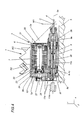
- Figure 2, with reference to the same configuration in which the head kinematic chain is illustrated in the previous figure, is a front view, according to the tool axis, of the compact motor-driven operating unit only;
- Figure 3 derives from Figure 1, but the compact motor-driven unit is represented in cross-section, with the operating axis parallel with the machine worktable, for routing/boring with a horizontal axis;
- Figure 4 is directly taken from Figure 3, but further enlarged.
- This device in the form of a
jointed machining head 1, particularly innovative as regards the solution relating to the compact motor-driven operating unit proposed, and at the same time very simple, basically comprises a kinematic chain with substantially known layout, consisting of threelimbs limbs limbs limb 17, immediately downstream of the joint R2, has aspecial casing 6 structure, forming the outer cover of the compact motor-drivenunit 3 which supports and drives thetool 4, and designed to enclose its mechanisms. - The
head limb 15 is, in turn, slidably supported by amachine slide 18, inserted between thehead limb 15 and themachine upright 19, which is mobile along its X axis. Theslide 18 in turn has bothguides 18g on one of its faces, angled according to the Z axis and on which thelimb 15 can slide vertically, and counter-guides on its other face, designed to allow theslide 18 to slide on theguides 19g on the upright, angled according to the direction Y. Therefore, theslide 18 is a type of cross-shaped slide which, combined with the mobility of the upright 19 in direction X, guarantees the three degrees of freedom in head translation X, Y, Z. - Obviously, the joints R1 and R2, like the other movements, are motor-driven and controlled according to the usual solutions (which are, therefore, not described in further detail), designed to allow the desired positioning of the
head 1 limbs in predetermined successive configurations, and in particular to angle the tool axis according to any direction. - The joint R1 by which the
limb 15 supports thenext limb 16, is positioned in such a way that its axis of rotation W1 is perpendicular to themachine worktable 5, designed for fixing theworkpieces 2, and therefore angled like the machine Z axis. - The subsequent joint R2, by which the
limb 16 supports thenext limb 17, is positioned in such a way that its axis of rotation W2 is incident with the previous axis W1 at a point C on it, and so that the axis W2 is set at 45° to the axis W1. In this way, the axis W2 is also set at 45° to themachine worktable 5 and, thanks to the joint R1, the axis W2 can describe the lateral surface of a cone with vertex C and axis W1, having half-opening equal to 45°. - In other words, rotation of the
limb 16 on thelimb 15 induces rotation of the axis W2 about the vertical axis W1 according to the aforementioned method. - Immediately downstream of the joint R2, and rotatably connected by it to the
previous limb 16, is thelimb 17, as indicated above. - The part of the
limb 17 adjacent to the joint R2 has a flat connecting surface to which thecasing 6 is attached by threaded connections. The casing delimits the compact motor-drivenunit 3 which supports and drives thetool 4, considered part of thethird limb 17. - The
unit 3casing 6 is particularly suitable for housing twoparallel shafts casing 6 about respectivegeometrical axes shaft 8 is designed to support the routing/boring tool, as indicated in further detail below. - The connection between the
casing 6 and the flat surface of thelimb 17 is, during construction, made such that the plane identified by the twoparallel axes limb 17, where the angle according to which theparallel axes - It should be noticed that these geometrical requirements may be satisfied by the methods used for construction of the
individual limb 17, since in said limb the axis of rotation W2 of the joint R2 is perfectly identified - irrespective of the connection to the previous limb 16 - by the part of joint R2 included in thelimb 17 and designed to be connected to the remaining part of the joint R2 included in theother limb 16. - Another
important head 1 characteristic derives from the correct provision of the method used to connect thelimb 17 to thelimb 16. That is to say, the characteristic by which the point at which theaxes 8a and W2 meet coincides with the point C previously defined as the intersection of axes W1 and W2, where in particular this property is achieved by correctly setting the axial distance between the ring nuts of the joint R2. - The above-mentioned mutual relationships which-for correct interaction - connect the elements of the supporting kinematic chain, some aspects of which are known, and the special production features of the motor-driven
tool holder unit 3, confirm the fact that thehead 1 must be considered a single functional assembly, in which operation is guaranteed - in accordance with the claims and the description of the present invention - both by observing the mutual arrangements between the elements of the kinematic chain and those of theoperating unit 3, and by the special features of theunit 3. - The structure of the compact motor-driven
unit 3 is now described in greater detail. - As already indicated, it is delimited by the
casing 6, and is substantially separated into two parts, of which one is a driving part, extending around ageometrical axis 7a, and one is an operating part, driving the tool and extending around ageometrical axis 8a. Theaxes casing 6 by relative bearing seats and are parallel with one another. - The driving part has an electric motor whose rotor is a
shaft 7 withgeometrical axis 7a, supported by thecasing 6 by means of rolling bearings, and which has a conventional electric pack consisting of a rotor which in turn - with an air gap - turns in a conventional electric pack consisting of stator windings, according to customary electrical engineering solutions. - At one end of the shaft 7 - which may be called the front relative to the front of the operating unit 3 - the casing has a
secondary service cover 20, for maintenance or substituting the front supporting bearing, whilst at the opposite end - which may be called the back - theshaft 7 has atoothed pulley 7p for atoothed belt 10, and is supported by a rear bearing. - At the ends of the
shaft 7, thecasing 6 also hasend plates casing 6, to give it the modularity which allows the assembly/disassembly of internal parts, according to the solutions applied in the shaft casings. The upper part of Figure 2 illustrates both thesecondary service cover 20, and theremovable end plate 21 of thecasing 6, designed to support the bearing on the front end of theshaft 7. - In contrast to the
end plate 21, in view in thecasing 6 and forming the casing front closure, theend plate 22 which is the seat of theshaft 7 rear bearing, is inside thecasing 6. - Continuing the structural description in the direction of transmission of the motion originating from the driving
shaft 7, there is - keyed to the shaft 7 - thepulley 7p which transmits the motion to thetoothed belt 10, which in turn transmits it to the operating part of theunit 3. - Said operating part is separated from the driving part by an
incomplete ridge 29, which also has structural functions for thecasing 6, and identifies a compartment in thecasing 6 which, with reference to ahorizontal shaft 7 position, is below the compartment where the driving part is located. An axiallyhollow shaft 8, withgeometrical axis 8a and supported by roller bearings in the lower part of thecasing 6, is the basic element of the operating part. - At one
end 8f of the shaft, the back, being located at thepulley 7p of theprevious shaft 7, atoothed pulley 8p is keyed, suitable for engaging with thetoothed belt 10, and for using the belt to receive the motion generated by the drivingshaft 7. - At the
other end 8e of the shaft 8 - which may be called the operating end, since thetool 4 is positioned on it - the casing has an opening forshaft 8 output, with acover 28 that also has an opening, partly designed to retain bearings located at the operatingend 8e. Figure 2 provides a front view of the fastening screws and the edge of thecover 28. As is also evident in Figure 4, the radial dimension necessary to support the operatingshaft 8 is noticeably reduced compared with that required for the drivingshaft 7, which must be surrounded not only by the bearings, but also by the rotor and stator electric packs. - As indicated, the
shaft 8 has an axial through cavity, terminating at the operatingend 8e in a cone-shaped seat, and suitable for receiving standard taper shanks, for example, of the HSK type in accordance with DIN standards. The axial cavity housespart 11b of the set of systems 11 usually used to lock/release the holder of thetool 4, that is to say, a control rod, a pack of Belleville washers surrounding the rod, and the tool holder expanding collet, some of these elements only partially illustrated in the accompanying drawings, or not at all in the cavity, since they refer to prior art. Thepart 11b of the set of locking/release systems 11 housed in the shaft cavity is driven by anactuator part 11a for the set of systems 11. Theactuator part 11a consists of a shapedplate 23, connected on one side to theend plate 22 and to other elements of thecasing 6, whilst the other side forms the body of a pneumatic cylinder withgeometrical axis 7a, having a cylindrical cavity for a large-diameter piston 24 driven by compressed air, which slides along theaxis 7a. Acover 26 acts as the base for both the body of the pneumatic cylinder and theunit 3casing 6, and also has a fulcrum for arocker arm 25, which transfers thepiston 24 stroke to the tool release control rod. - In said pneumatic cylinder, the air arriving from the distribution network flows to/from the two chambers in the cylinder through special holes, and using customary pneumatic distribution components, controlled by a control device.
- A
light service cover 27 is located at the very back of thecasing 6, protecting the rocker arm from dust. There is a hole at theshaft 8axis 8a, that is to say, the shaft which slides inside it. - In an alternative embodiment to the one described above, the
actuator part 11a of the locking/release means 11 may be connected to ahead 1limb 11m, separated from theunit 3, both to make theunit 3 lighter and to avoid the presence of relative tubes for pressurised air arriving as far as theunit 3, for controlling the pneumatic cylinder. Obviously-in such architectures - the tool is only unlocked with thehead 1 in a kinematic chain configuration in which theparts part 11a can act upon the control rod by means of the passage represented by the hole in thelight cover 27. - Operationally, the device structured in this way in the form of a
head 1 with a motor-driventool drive unit 3, fulfils the preset aims thanks to the mutual arrangements of the various elements illustrated, without having to change the remaining machine structure which already exists. - As regards the movements of the kinematic chain which supports the motor-driven
unit 3, it may be observed that, as described above, relative to the mutual positions for the geometrical elements of thehead 1, the geometrical axes W1, W2 and 8a converge at point C where - thanks to rotation of thelimb 16 on the joint R1 - the axis W2 can describe a conical surface with vertex C, with axis W1 and half-opening equal to 45°, whilst - thanks to rotation of thelimb 17 on the joint R2 - theaxis 8a can describe a conical surface with vertex C, with axis W2 and half-opening equal to 45°. - The two types of rotation - about W2 and about W1-can demonstrate how the
tool axis 8a can be angled according to any of the straight lines belonging to the star with point C as the support, and in particular - as illustrated in Figure 1 - it can assume all directions in the horizontal plane, that is to say, parallel with theworktable 5, and the vertical direction coinciding with the axis W1, that is to say, perpendicular to theworktable 5. The direction identified by the tip of the tool always has a component facing theworktable 5, which may be null at most. In practice, with point C being fixed, the position of thetool 4axis 8a is identified by the point C and by any other point Q of theaxis 8a, where the motion of the point Q-by construction - must occur on a spherical surface with centre C and radius CQ, designed to represent a movement by a rigid body with a fixed point. - The possibilities for movement deriving from the mobility of the
upright 19 and theslide 18 on it, as well as thelimb 15 on theslide 18, guarantee the possibility of placing point C at any point in the operating zone of themachine worktable 5. - On the joints R1 and R2 (or rather on their ring nuts) there is a fixed origin of the respective angles of rotation and a measuring scale for them. The angles measured on such R1 and R2 scales form a pair of parameters necessary and sufficient for identifying the geometrical configuration of the
head 1, that is to say, for defining the position of the tool axis, where - starting for example from the respective origins on the graduated scales-the order with which rotations on the two joints are attributed has no influence, since the two axes are not absolutely fixed in space (as this would prevent switching of the composition of the finished rotations), but the second axis W2 is rotated by the first axis W1. In other words, the two rotations measured on the joints R1 and R2 constitute two parameters, known as Lagrangians, which unambiguously identify the system configuration, where, as is known, said configuration does not depend on the order with which such parameters are assigned. - As regards operation inside the
unit 3 it is evident, partly with the aid of Figure 4, that the rotary motion generated by the electric motor with theshaft 7 as the rotor is transmitted to the adjacent andparallel shaft 8 by the system consisting of theshaft 7pulley 7p, thetoothed belt 10, and theshaft 8pulley 8p. Thetool 4, with the relative tool holder, is supported at the operatingend 8e of theshaft 8 and projects from theunit 3casing 6, and can perform boring/routing machining operations on theworkpiece 2 fixed to themachine worktable 5. - The operation of the tool release device is easily explainable by observing that, while the
piston 24 performs an active release stroke, towards the back of thecasing 6, the relative rod activates therocker arm 25, which acts upon the release rod contained in the shaft cavity, where the rod return stroke - and that of the piston 24 - is directly controlled by the elastic reaction of the Belleville washers acting between theshaft 8 and the rod. - It is important to emphasise again, as already indicated relative to the fact that (see Figure 2) the reduced dimension of the motor-driven unit 3-in particular along the radial half-lines s originating from the operating
axis 8a and moving away from the drivingaxis 7a - allow theunit 3 to approach theworktable 5, getting very close to it, for allhead 1 machining configurations in which theaxis 8a is horizontal, for example for horizontal routing/boring. Therefore, it is thanks to the special configuration of the invention described that, with thetool axis 8a substantially horizontal, machining can be performed with tool axis heights H very much lower relative to themachine worktable 5, in other words, providing the system with a minimum machining height Hmin allowed that is very low on theworktable 5, giving optimum accessibility on the lateral walls of a workpiece, even if the workpiece is fixed directly to themachine worktable 5. - The invention described can be subject to modifications and variations without thereby departing from the scope of the inventive concept. Moreover, all the details of the invention may be substituted by technically equivalent elements.
Claims (9)
- A jointed machining head (1), for machine tools used to machine workpieces (2) made of wood or similar materials which are secured to a machine worktable (5), the head configured in the form of a kinematic chain with at least one first joint (R1) capable of rotation about at least one joint geometrical axis (W1); the head comprising a compact motor-driven unit (3), designed to rotationally drive a tool (4) rapidly about an axis identified in the unit (3) in order to perform routing, boring and similar operations on the workpieces (2); it being possible to position the compact motor-driven unit (3) using the kinematic chain at least in an operating position (12) in which the tool (4) axis of rapid rotation is parallel with the machine worktable (5), the head being characterised in that the compact motor-driven unit (3) comprises, in a shaft support casing (6), a first, driving part, consisting of an electric motor whose rotor is a first, driving shaft (7), having a first axis of rotation (7a) in the unit (3); and a second, operating part, consisting of a second, operating shaft (8), having a second axis of rotation (8a) in the unit (3), parallel with and close to the previous axis of rotation (7a), and having an operating end (8e), designed to coaxially support the tool (4) operating outside the casing (6), the end (8e) allowing the tool (4) to assume the second axis of rotation (8a) as is axis of rapid rotation; the second shaft (8) being rotationally driven by the first shaft (7) through means (9) for transmitting rotational motion; where, due to the absence of the electric pack on the second shaft (8), the casing (6) is advantageously made with a much reduced dimension along the radial half-lines (s) originating from the second axis of rotation (8a) and moving away from the first axis of rotation (7a), so that in the one or more operating positions (12), the radial distance between the second, operating shaft (8) and the machine worktable (5), and each individual workpiece (2) being machined, is very small.
- The jointed machining head (1) for machine tools according to claim 1, characterised in that in the unit (3), the rotary motion transmission means (9) for driving the second shaft (8) by means of the first shaft (7), are located in the casing (6), and consist of two toothed pulleys (7p) and (8p), respectively keyed to the shafts (7) and (8), and a toothed belt (10) for transmission between the pulleys.
- The jointed machining head (1) for machine tools according to claim 2, characterised in that in the unit (3), on the first shaft (7) and the second shaft (8), the toothed pulleys (7p) and (8p) are keyed at a section made with a plane perpendicular to the shafts, which meets the operating shaft (8) substantially at the end (8f) of the latter, opposite the operating end (8e).
- The jointed machining head (1) for machine tools according to any of the foregoing claims, characterised in that in the unit (3), the second, operating shaft (8) is axially hollow, there being means (11) for locking/releasing the tool on/from the operating end (8e) of the shaft, said means (11) being partly located on the side of the end (8f) opposite the operating end (8e), and partly passing through the second shaft (8) in an axial direction.
- The jointed machining head (1) for machine tools according to any of the claims from 1 to 3, characterised in that the second, operating shaft (8) is axially hollow, there being means (11) for locking/releasing the tool on/from the operating end (8e) of the shaft; a first, actuator part (11a) of the means (11) being attached to a head (1) limb (11m), separated from the unit (3), and a second part (11b) of the means (11) being attached to the unit (3), passing through the shaft (8) axially, it being possible to activate it using the first actuator part (11a), in at least one configuration of the kinematic chain which forms the head (1)-designed at least to release the tool - in which the parts (11a and (11b are positioned so that they are adjacent.
- The jointed machining head (1) for machine tools according to any of the foregoing claims, characterised in that the geometrical axis (W1) about which the first joint (R1) can rotate, is perpendicular to the machine worktable (5), and the second axis of rotation (8a) is parallel with the machine (5) worktable, for at least one configuration of the kinematic chain which forms the jointed machining head (1).
- The jointed machining head (1) for machine tools according to claim 6, characterised in that the plane identified by the two axes of rotation (7a) and (8a) is perpendicular to the machine worktable (5) where, of the two shafts, the first, driving shaft (7) and the second, operating shaft (8), the latter is closer to the machine worktable (5).
- The jointed machining head (1) for machine tools according to any of the foregoing claims, in which the kinematic chain which forms the head (1) has at least one second joint (R2) capable of rotation about at least one joint geometrical axis (W2), the head being characterised in that the second axis (8a) about which the tool (4) is rapidly turned, and the geometrical axes (W1) and (W2), are incident with one another at a point (C), at least for a set of positions (13) of the kinematic chain; where, within this set of positions (13), the first joint (R1) allows rotation of the axis (W2) about the axis (W1) according to a first cone with vertex (C) and half-opening equal to 45°, the second joint (R2) allowing rotation, independent of the previous movements, of the second axis (8a) about the axis (W2) according to a second cone with vertex (C) and half-opening equal to 45°.
- The jointed machining head (1) for machine tools according to claim 8, characterised in that the axis of rotation (W1) is constantly perpendicular to the machine worktable (5), at least for a set of positions (14) in the set of positions (13) of the kinematic chain; such that in the positions (14) the axis of rotation (8a) may occupy - by 180° rotation about the axis (W2) - both the operating position parallel with the machine worktable (5), and the operating position perpendicular to the worktable (5), and coinciding with the axis (W1).
Applications Claiming Priority (2)
| Application Number | Priority Date | Filing Date | Title |
|---|---|---|---|
| ITRN20020012U | 2002-05-13 | ||
| IT2002RN000012U ITRN20020012U1 (en) | 2002-05-13 | 2002-05-13 | ANTHROPOMORPHIC HEAD FOR MACHINE TOOLS WITH REDUCED RADIAL DIMENSION OPERATING UNIT |
Publications (2)
| Publication Number | Publication Date |
|---|---|
| EP1362665A1 true EP1362665A1 (en) | 2003-11-19 |
| EP1362665B1 EP1362665B1 (en) | 2006-01-18 |
Family
ID=11456737
Family Applications (1)
| Application Number | Title | Priority Date | Filing Date |
|---|---|---|---|
| EP03425302A Expired - Lifetime EP1362665B1 (en) | 2002-05-13 | 2003-05-12 | An anthropomorphic head for machine tools with an operating unit with reduced radial dimension |
Country Status (5)
| Country | Link |
|---|---|
| EP (1) | EP1362665B1 (en) |
| AT (1) | ATE315977T1 (en) |
| DE (1) | DE60303285T2 (en) |
| ES (1) | ES2258711T3 (en) |
| IT (1) | ITRN20020012U1 (en) |
Cited By (1)
| Publication number | Priority date | Publication date | Assignee | Title |
|---|---|---|---|---|
| EP3603882A4 (en) * | 2017-03-31 | 2020-11-25 | Makino Milling Machine Co., Ltd. | Machine tool |
Families Citing this family (2)
| Publication number | Priority date | Publication date | Assignee | Title |
|---|---|---|---|---|
| DE102008007293B4 (en) * | 2007-02-09 | 2019-08-14 | Breton S.P.A. | Automatic machine tool clamping head with second axis rotation inclined 45 ° relative to the first axis, and with a mechanical spindle unit interchangeable with a high speed motor spindle unit |
| DE102017118901A1 (en) | 2017-08-18 | 2019-02-21 | Homag Gmbh | Machining head with axis clamping device and processing device |
Citations (3)
| Publication number | Priority date | Publication date | Assignee | Title |
|---|---|---|---|---|
| DE2451292A1 (en) * | 1974-10-29 | 1976-05-06 | Metabowerke Kg | Hand drill for dowel holing |
| DE3219072A1 (en) * | 1981-05-27 | 1983-01-13 | Lino Busellato s.d.f. di L. Busellato & C., Piovene Rocchette, Vicenza | Method of making accurately positioned bores in plates or similar workpieces with a plane surface and drilling machine for implementing the new method |
| US5533846A (en) * | 1994-01-25 | 1996-07-09 | Deckel Maho Gmbh | Universal milling and drilling machine |
-
2002
- 2002-05-13 IT IT2002RN000012U patent/ITRN20020012U1/en unknown
-
2003
- 2003-05-12 EP EP03425302A patent/EP1362665B1/en not_active Expired - Lifetime
- 2003-05-12 AT AT03425302T patent/ATE315977T1/en not_active IP Right Cessation
- 2003-05-12 ES ES03425302T patent/ES2258711T3/en not_active Expired - Lifetime
- 2003-05-12 DE DE60303285T patent/DE60303285T2/en not_active Expired - Lifetime
Patent Citations (3)
| Publication number | Priority date | Publication date | Assignee | Title |
|---|---|---|---|---|
| DE2451292A1 (en) * | 1974-10-29 | 1976-05-06 | Metabowerke Kg | Hand drill for dowel holing |
| DE3219072A1 (en) * | 1981-05-27 | 1983-01-13 | Lino Busellato s.d.f. di L. Busellato & C., Piovene Rocchette, Vicenza | Method of making accurately positioned bores in plates or similar workpieces with a plane surface and drilling machine for implementing the new method |
| US5533846A (en) * | 1994-01-25 | 1996-07-09 | Deckel Maho Gmbh | Universal milling and drilling machine |
Cited By (1)
| Publication number | Priority date | Publication date | Assignee | Title |
|---|---|---|---|---|
| EP3603882A4 (en) * | 2017-03-31 | 2020-11-25 | Makino Milling Machine Co., Ltd. | Machine tool |
Also Published As
| Publication number | Publication date |
|---|---|
| DE60303285T2 (en) | 2006-09-14 |
| ES2258711T3 (en) | 2006-09-01 |
| ITRN20020012V0 (en) | 2002-05-13 |
| EP1362665B1 (en) | 2006-01-18 |
| ATE315977T1 (en) | 2006-02-15 |
| ITRN20020012U1 (en) | 2003-11-13 |
| DE60303285D1 (en) | 2006-04-06 |
Similar Documents
| Publication | Publication Date | Title |
|---|---|---|
| CN101036969B (en) | Machine tool and method for machining workpieces, especially metal workpieces | |
| US6287245B1 (en) | Deep drilling device | |
| US8061939B2 (en) | Attachment unit for five-face machining | |
| US5943750A (en) | Reconfigurable machine tool | |
| TWI727067B (en) | Working machinery | |
| AU2014204532B2 (en) | Machine tool and method for the machining of workpieces having at least two separate machining units | |
| EP1642676B1 (en) | Turret for machine tool | |
| CN109605063B (en) | Small five-axis engraving and milling machine tool | |
| CN112318145A (en) | A CNC gantry compound machine | |
| CN114799890B (en) | Turning and milling composite machining center | |
| CN112171252A (en) | Multifunctional assembly rotary table with fixed-moment tightening mechanism and assembly method | |
| US20120076598A1 (en) | Milling machine for producing toothed wheels | |
| EP1362665B1 (en) | An anthropomorphic head for machine tools with an operating unit with reduced radial dimension | |
| ZA200602407B (en) | Clamping table comprising a telescopic tube unit and a clamping element that is provided with suction cups | |
| US6183172B1 (en) | Structure for detachably mounting a horizontal drill head | |
| CN115971539A (en) | Butterfly valve machining equipment and method | |
| CN213531601U (en) | Numerical control gantry compound machine | |
| KR20050019510A (en) | Assembling machine with two rotary axes | |
| CN216912933U (en) | Swing revolving stage of removable workstation | |
| JPS62218008A (en) | Multi-spindle machine tool | |
| US6807887B2 (en) | Multiple-spindle bar machine | |
| KR102646290B1 (en) | Table detachable assembly for 5-axis process of 3-axis machine tools | |
| CN117655362A (en) | A large CNC lathe and modular processing device | |
| JP4106535B2 (en) | Internal processing equipment | |
| US12285812B2 (en) | Device for machining window or door frames welded from profile pieces |
Legal Events
| Date | Code | Title | Description |
|---|---|---|---|
| PUAI | Public reference made under article 153(3) epc to a published international application that has entered the european phase |
Free format text: ORIGINAL CODE: 0009012 |
|
| AK | Designated contracting states |
Kind code of ref document: A1 Designated state(s): AT BE BG CH CY CZ DE DK EE ES FI FR GB GR HU IE IT LI LU MC NL PT RO SE SI SK TR |
|
| AX | Request for extension of the european patent |
Extension state: AL LT LV MK |
|
| 17P | Request for examination filed |
Effective date: 20031009 |
|
| AKX | Designation fees paid |
Designated state(s): AT BE BG CH CY CZ DE DK EE ES FI FR GB GR HU IE IT LI LU MC NL PT RO SE SI SK TR |
|
| 17Q | First examination report despatched |
Effective date: 20050308 |
|
| GRAP | Despatch of communication of intention to grant a patent |
Free format text: ORIGINAL CODE: EPIDOSNIGR1 |
|
| GRAS | Grant fee paid |
Free format text: ORIGINAL CODE: EPIDOSNIGR3 |
|
| GRAA | (expected) grant |
Free format text: ORIGINAL CODE: 0009210 |
|
| AK | Designated contracting states |
Kind code of ref document: B1 Designated state(s): AT BE BG CH CY CZ DE DK EE ES FI FR GB GR HU IE IT LI LU MC NL PT RO SE SI SK TR |
|
| PG25 | Lapsed in a contracting state [announced via postgrant information from national office to epo] |
Ref country code: SI Free format text: LAPSE BECAUSE OF FAILURE TO SUBMIT A TRANSLATION OF THE DESCRIPTION OR TO PAY THE FEE WITHIN THE PRESCRIBED TIME-LIMIT Effective date: 20060118 Ref country code: AT Free format text: LAPSE BECAUSE OF FAILURE TO SUBMIT A TRANSLATION OF THE DESCRIPTION OR TO PAY THE FEE WITHIN THE PRESCRIBED TIME-LIMIT Effective date: 20060118 Ref country code: LI Free format text: LAPSE BECAUSE OF FAILURE TO SUBMIT A TRANSLATION OF THE DESCRIPTION OR TO PAY THE FEE WITHIN THE PRESCRIBED TIME-LIMIT Effective date: 20060118 Ref country code: BE Free format text: LAPSE BECAUSE OF FAILURE TO SUBMIT A TRANSLATION OF THE DESCRIPTION OR TO PAY THE FEE WITHIN THE PRESCRIBED TIME-LIMIT Effective date: 20060118 Ref country code: SK Free format text: LAPSE BECAUSE OF FAILURE TO SUBMIT A TRANSLATION OF THE DESCRIPTION OR TO PAY THE FEE WITHIN THE PRESCRIBED TIME-LIMIT Effective date: 20060118 Ref country code: FI Free format text: LAPSE BECAUSE OF FAILURE TO SUBMIT A TRANSLATION OF THE DESCRIPTION OR TO PAY THE FEE WITHIN THE PRESCRIBED TIME-LIMIT Effective date: 20060118 Ref country code: NL Free format text: LAPSE BECAUSE OF FAILURE TO SUBMIT A TRANSLATION OF THE DESCRIPTION OR TO PAY THE FEE WITHIN THE PRESCRIBED TIME-LIMIT Effective date: 20060118 Ref country code: RO Free format text: LAPSE BECAUSE OF FAILURE TO SUBMIT A TRANSLATION OF THE DESCRIPTION OR TO PAY THE FEE WITHIN THE PRESCRIBED TIME-LIMIT Effective date: 20060118 Ref country code: CH Free format text: LAPSE BECAUSE OF FAILURE TO SUBMIT A TRANSLATION OF THE DESCRIPTION OR TO PAY THE FEE WITHIN THE PRESCRIBED TIME-LIMIT Effective date: 20060118 |
|
| REG | Reference to a national code |
Ref country code: GB Ref legal event code: FG4D |
|
| REG | Reference to a national code |
Ref country code: CH Ref legal event code: EP |
|
| REG | Reference to a national code |
Ref country code: IE Ref legal event code: FG4D |
|
| REF | Corresponds to: |
Ref document number: 60303285 Country of ref document: DE Date of ref document: 20060406 Kind code of ref document: P |
|
| PG25 | Lapsed in a contracting state [announced via postgrant information from national office to epo] |
Ref country code: SE Free format text: LAPSE BECAUSE OF FAILURE TO SUBMIT A TRANSLATION OF THE DESCRIPTION OR TO PAY THE FEE WITHIN THE PRESCRIBED TIME-LIMIT Effective date: 20060418 Ref country code: DK Free format text: LAPSE BECAUSE OF FAILURE TO SUBMIT A TRANSLATION OF THE DESCRIPTION OR TO PAY THE FEE WITHIN THE PRESCRIBED TIME-LIMIT Effective date: 20060418 Ref country code: BG Free format text: LAPSE BECAUSE OF FAILURE TO SUBMIT A TRANSLATION OF THE DESCRIPTION OR TO PAY THE FEE WITHIN THE PRESCRIBED TIME-LIMIT Effective date: 20060418 |
|
| PG25 | Lapsed in a contracting state [announced via postgrant information from national office to epo] |
Ref country code: IE Free format text: LAPSE BECAUSE OF NON-PAYMENT OF DUE FEES Effective date: 20060512 |
|
| PG25 | Lapsed in a contracting state [announced via postgrant information from national office to epo] |
Ref country code: MC Free format text: LAPSE BECAUSE OF NON-PAYMENT OF DUE FEES Effective date: 20060531 |
|
| PG25 | Lapsed in a contracting state [announced via postgrant information from national office to epo] |
Ref country code: PT Free format text: LAPSE BECAUSE OF FAILURE TO SUBMIT A TRANSLATION OF THE DESCRIPTION OR TO PAY THE FEE WITHIN THE PRESCRIBED TIME-LIMIT Effective date: 20060619 |
|
| NLV1 | Nl: lapsed or annulled due to failure to fulfill the requirements of art. 29p and 29m of the patents act | ||
| REG | Reference to a national code |
Ref country code: CH Ref legal event code: PL |
|
| REG | Reference to a national code |
Ref country code: ES Ref legal event code: FG2A Ref document number: 2258711 Country of ref document: ES Kind code of ref document: T3 |
|
| ET | Fr: translation filed | ||
| PLBE | No opposition filed within time limit |
Free format text: ORIGINAL CODE: 0009261 |
|
| STAA | Information on the status of an ep patent application or granted ep patent |
Free format text: STATUS: NO OPPOSITION FILED WITHIN TIME LIMIT |
|
| 26N | No opposition filed |
Effective date: 20061019 |
|
| PG25 | Lapsed in a contracting state [announced via postgrant information from national office to epo] |
Ref country code: GR Free format text: LAPSE BECAUSE OF FAILURE TO SUBMIT A TRANSLATION OF THE DESCRIPTION OR TO PAY THE FEE WITHIN THE PRESCRIBED TIME-LIMIT Effective date: 20060419 Ref country code: CZ Free format text: LAPSE BECAUSE OF FAILURE TO SUBMIT A TRANSLATION OF THE DESCRIPTION OR TO PAY THE FEE WITHIN THE PRESCRIBED TIME-LIMIT Effective date: 20060118 |
|
| PG25 | Lapsed in a contracting state [announced via postgrant information from national office to epo] |
Ref country code: EE Free format text: LAPSE BECAUSE OF FAILURE TO SUBMIT A TRANSLATION OF THE DESCRIPTION OR TO PAY THE FEE WITHIN THE PRESCRIBED TIME-LIMIT Effective date: 20060118 |
|
| PG25 | Lapsed in a contracting state [announced via postgrant information from national office to epo] |
Ref country code: TR Free format text: LAPSE BECAUSE OF FAILURE TO SUBMIT A TRANSLATION OF THE DESCRIPTION OR TO PAY THE FEE WITHIN THE PRESCRIBED TIME-LIMIT Effective date: 20060118 Ref country code: HU Free format text: LAPSE BECAUSE OF FAILURE TO SUBMIT A TRANSLATION OF THE DESCRIPTION OR TO PAY THE FEE WITHIN THE PRESCRIBED TIME-LIMIT Effective date: 20060719 Ref country code: LU Free format text: LAPSE BECAUSE OF NON-PAYMENT OF DUE FEES Effective date: 20060512 |
|
| PG25 | Lapsed in a contracting state [announced via postgrant information from national office to epo] |
Ref country code: CY Free format text: LAPSE BECAUSE OF FAILURE TO SUBMIT A TRANSLATION OF THE DESCRIPTION OR TO PAY THE FEE WITHIN THE PRESCRIBED TIME-LIMIT Effective date: 20060118 |
|
| REG | Reference to a national code |
Ref country code: FR Ref legal event code: PLFP Year of fee payment: 14 |
|
| REG | Reference to a national code |
Ref country code: FR Ref legal event code: PLFP Year of fee payment: 15 |
|
| REG | Reference to a national code |
Ref country code: FR Ref legal event code: PLFP Year of fee payment: 16 |
|
| PGFP | Annual fee paid to national office [announced via postgrant information from national office to epo] |
Ref country code: IT Payment date: 20220407 Year of fee payment: 20 Ref country code: GB Payment date: 20220523 Year of fee payment: 20 Ref country code: FR Payment date: 20220524 Year of fee payment: 20 Ref country code: ES Payment date: 20220617 Year of fee payment: 20 Ref country code: DE Payment date: 20220519 Year of fee payment: 20 |
|
| REG | Reference to a national code |
Ref country code: DE Ref legal event code: R071 Ref document number: 60303285 Country of ref document: DE |
|
| REG | Reference to a national code |
Ref country code: ES Ref legal event code: FD2A Effective date: 20230526 |
|
| REG | Reference to a national code |
Ref country code: GB Ref legal event code: PE20 Expiry date: 20230511 |
|
| PG25 | Lapsed in a contracting state [announced via postgrant information from national office to epo] |
Ref country code: ES Free format text: LAPSE BECAUSE OF EXPIRATION OF PROTECTION Effective date: 20230513 |
|
| PG25 | Lapsed in a contracting state [announced via postgrant information from national office to epo] |
Ref country code: GB Free format text: LAPSE BECAUSE OF EXPIRATION OF PROTECTION Effective date: 20230511 |