FIELD OF THE INVENTION
-
The present invention relates to a base station apparatus,
a communication terminal apparatus, and a wireless communication
method.
BACKGROUND ART
-
An adaptive modulation scheme is a scheme which changes
modulation signals and data transmission rates in accordance
with the conditions of a propagation path of a communication
terminal apparatus. In such an adaptive modulation scheme,
signals are transmitted at a high transmission rate for a
communication terminal apparatus of which the conditions of a
propagation path are good, whilst signals are transmitted at
a low transmission rate for a communication terminal apparatus
of which the conditions of a propagation path are poor, thereby
improving the throughput of a wireless communication system as
a whole.
-
In a wireless communication system which adopts a
conventional adaptive modulation scheme, a communication
terminal apparatus measures the quality of wireless transmission
with a known signal which is transmitted from a base station
apparatus, and the base station apparatus changes modulation
signals in accordance with the result of the measurement.
-
A wireless communication system which adopts a
conventional adaptive modulation signal scheme is explained here
with reference to FIG. 1. FIG. 1 is a block diagram illustrating
a wireless communication system which adopts a conventional
adaptive modulation signal scheme.
-
First of all, the configuration of a conventional base
station apparatus is described. In FIG. 1, abase station apparatus
comprises known signal generation section 11, transmission
section 12, reception section 13, transmission scheme
determination section 14, channel codec section 15, and data
generation section 16.
-
Next, the configuration of a conventional communication
terminal apparatus is described. In FIG. 1, a communication
terminal apparatus comprises reception section 17, instantaneous
power measurement section 18, averaging section 19, wireless
quality reporting section 20, and transmission section 21.
-
Next, the operation of a wireless communication system
which adopts a conventional adaptive modulation signal scheme
is explained here with reference to FIG. 1.
-
First, at the base station apparatus, known signal
generation section 11 generates a known signal, and transmits
the generated known signal to the communication terminal
apparatus via transmission section 12.
-
Next, at the communication terminal apparatus,
instantaneous power measurement section 18 measures the
instantaneous power values of the known signals received via
reception section 17, and averaging section 19 performs averaging
on the measured instantaneous power values to calculate an
averaged power value and a noise power value. Wireless quality
reporting section 20 transmits a control signal indicating
wireless quality derived from the averaged power value of the
known signals and the noise power value thereof to the base station
apparatus via transmission section 21. Herein, a time period
for the averaging of the instantaneous power values by averaging
section 19 is predetermined, which is a fixed value of length
for a mobile device.
-
Then, at the base station apparatus, transmission scheme
determination section 14 determines a transmission scheme
(modulation scheme and coding rate) based on the wireless quality
indicated by the control signal received via reception section
13, channel codec section 15 performs the encoding of transmission
data in the determined coding rate, and data generation section
16 performs the modulation of the transmission data encoded in
the determined modulation scheme to output the modulated
transmission data for transmission to the communication terminal
apparatus via transmission section 12.
-
As described above, according to a wireless communication
-system which adopts a conventional adaptive modulation scheme,
a base station apparatus judges the conditions of a propagation
path based on the wireless quality indicated by a control signal
received from a communication terminal apparatus, and signals
are transmitted at a high transmission rate for a communication
terminal apparatus of which the conditions of the propagation
path are good, whilst signals are transmitted at a low transmission
rate for a communication terminal apparatus of which the
conditions of the propagation path are poor, thereby improving
the throughput of the wireless communication system as a whole.
-
However, in a wireless communication system which adopts
a conventional adaptive modulation scheme, a base station
apparatus judges the conditions of a propagation path based on
an averaged power value received from a communication terminal
apparatus, where such an averaged power value comes from averaging
for a fixed time period, and accordingly, there arises a problem
that the communication apparatus fails to keep track of changes
in the propagation path due to its moving speed, and so forth,
which causes the base station apparatus, based on the reported
wireless quality, to determine a transmission system which is
not the best one for the communication terminal apparatus.
-
That is, when averaging is performed for a short time period,
a communication terminal apparatus is able to keep track of changes
in a propagation path during the time of slow-speed moving on
a real-time basis, however, the communication terminal apparatus
fails to absorb abrupt variations sufficiently in the propagation
path due to fading during the time of fast-speed moving. On the
other hand, when averaging is performed for a long time period,
a communication terminal apparatus is able to absorb abrupt
variations due to fading sufficiently during the time of
fast-speedmoving, however, the communication terminal apparatus
fails to keep track of changes in wireless quality during the
time of slow-speed moving on a real-time basis.
DESCRIPTION OF THE INVENTION
-
The object of the present invention is to provide such
a base station apparatus, a communication terminal apparatus,
and a wireless communication method as one which allows the
communication terminal to perform averaging on power values in
accordance with the conditions of a propagation path to enhance
the reliability of a wireless quality value to be transmitted,
and allows the base station apparatus to determine an optimum
transmission scheme based on the reported value.
-
This object is achieved by judging the conditions of a
propagation path of a communication terminal apparatus (a moving
speed or a reception power fluctuation value) based on known
signals received by the base station apparatus from the
communication terminal apparatus or on known signals received
by the communication terminal apparatus from the base station
apparatus, and by controlling a time period for the averaging
of power values which is performed at the communication terminal
apparatus or by selecting an item to be reported, thereby
increasing the reliability of a power value reported to the base
station apparatus to ensure that an optimum transmission scheme
is determined based on the power value.
BRIEF DESCRIPTION OF THE DRAWINGS
-
- FIG. 1 is a block diagram illustrating the configuration
of a wireless communication system according to a conventional
example;
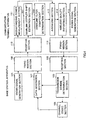
- FIG. 2 is a block diagram illustrating the configuration
of a wireless communication system according to Embodiment 1
of the present invention;
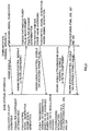
- FIG. 3 is a sequence diagram illustrating the operation
of a wireless communication system according to Embodiment 1
of the present invention;
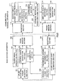
- FIG. 4 is a block diagram illustrating the configuration
of a wireless communication system according to Embodiment 2
of the present invention;
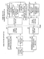
- FIG. 5 is a block diagram illustrating the configuration
of a wireless communication system according to Embodiment 3
of the present invention;
- FIG. 6 is a block diagram illustrating the configuration
of a wireless communication system according to Embodiment 4
of the present invention;
- FIG. 7 is a block diagram illustrating the configuration
of a wireless communication system according to Embodiment 5
of the present invention;
- FIG. 8 is a block diagram illustrating the configuration
of a wireless communication system according to Embodiment 6
of the present invention;
- FIG. 9 is a block diagram illustrating the configuration
of a wireless communication system according to Embodiment 7
of the present invention;
- FIG. 10 is a block diagram illustrating the configuration
of a wireless communication system according to Embodiment 8
of the present invention;
- FIG. 11 is a block diagram illustrating the configuration
of a wireless communication system according to Embodiment 9
of the present invention;
- FIG. 12 is a block diagram illustrating the configuration
of a wireless communication system according to Embodiment 10
of the present invention;
- FIG. 13 is a block diagram illustrating the configuration
of a wireless communication system according to Embodiment 11
of the present invention, and;
- FIG. 14 is a block diagram illustrating the configuration
of a wireless communication system according to Embodiment 12
of the present invention.
-
BEST MODE FOR CARRYING OUT THE INVENTION
-
Embodiments of the present invention will be described
below with reference to the accompanying drawings.
(Embodiment 1)
-
FIG. 2 is a block diagram illustrating the configuration
of a wireless communication system according to Embodiment 1
of the present invention.
-
First of all, a base station apparatus according to the
present invention will be described here with reference to FIG.
2. In FIG. 2, a base station apparatus comprises known signal
generation section 101, transmission section 102, reception
section 103, uplink Doppler shift estimation section 104,
transmission scheme determination section 105, channel codec
section 106, data generation section 107, uplink filter
coefficient determination section 108, and control signal
generation section 109.
-
Known signal generation section 101 generates a known
signal (a reference signal) which is made known to a communication
terminal apparatus, and transmission section 102 performs
wireless processing on the known signal, a control signal, and
other signals (transmission data) to transmit the processed
signals to the communication terminal apparatus.
-
Reception section 103 receives a control signal which
indicates a wireless quality value and a known signal (a pilot
signal) transmitted from the communication terminal apparatus.
Uplink Doppler shift estimation section 104 estimates the amount
of Doppler shift of the known signal. Uplink filter coefficient
determination section 108 determines a filter coefficient held
in the communication terminal apparatus based on the amount of
the Doppler shift. Control signal generation section 109
generates a control signal which indicates the filter
coefficient.
-
Then, transmission scheme determination section 105
determines a transmission scheme (modulation scheme and coding
rate) based on the wireless quality value indicated by the control
signal. Channel codec section 106 performs the encoding of
transmission data in the coding rate which is determined at
transmission scheme determination section 105. Data generation
section 107 performs the modulation of the transmission data
encoded in the modulation scheme which is determined at
transmission scheme determination section 105.
-
Next, a communication terminal apparatus according to the
present invention will be described here with reference to FIG.
2. In FIG. 2, a communication terminal apparatus comprises
reception section 110, instantaneous power measurement section
111, control information extraction section 112, averaging
section 113, wireless quality reporting section 114, known signal
generation section 115, and transmission section 116.
-
Reception section 110 receives a known signal and a control
signal transmitted from a base station apparatus. Instantaneous
power measurement section 111 measures the instantaneous power
values of the known signals. Control information extraction
section 112 modulates the control signal to extract a filter
coefficient.
-
Averaging section 113 performs averaging on the
instantaneous power values measured at instantaneous power
measurement section 111 based on the filter coefficient extracted
at control information extraction section 112 while measuring
the total noise power. Wireless quality reporting section 114
generates a control signal which indicates wireless quality from
the averaged power value and the noise power value of the averaged
known signal. Known signal generation section 115 generates a
known signal. Transmission section 116 performs wireless
processing on the known signal and the control signal to transmit
the processed signals to the base station apparatus.
-
Here, the operation of a wireless communication system
having the above-described configurations is described with
reference to sequence diagrams of FIG. 2 and FIG. 3. First, at
a communication terminal apparatus, known signal generation
section 115 generates a known signal, and transmission section
116 transmits the generated known signal to a base station
apparatus (F201).
-
Next, at the base station apparatus, uplink Doppler shift
estimation section 104 detects the spectrum of the known signal
received via reception section 103 to estimate the amount of
Doppler shift corresponding to a multiplexed wave. When detecting
the spectrum, detection is made by providing a plurality of
band-pass filters which allow signals to pass within a specific
frequency band only, and by measuring the output levels of
reception signals which have passed through the band-pass filters
or by performing Fourier transform processing on such reception
signals (F202).
-
Uplink filter coefficient determination section 108
determines a filter coefficient based on the amount of Doppler
shift estimated at uplink Doppler shift estimation section 104.
When determining the filter coefficient, the communication
terminal apparatus is judged to be moving at a high speed in
a case where the amount of the Doppler shift is large, and in
such a case, the determination is made in such a way that a long
time period is taken for averaging at averaging section 113 in
the communication terminal apparatus. On the other hand, the
communication terminal apparatus is judged to be moving at a
low speed in a case where the amount of the Doppler shift is
small, and in such a case, the determination is made in such
a way that a short time period is taken for averaging at averaging
section 113 in the communication terminal apparatus (F203).
-
Herein, the reason why a long time period is taken for
averaging at averaging section 113 in the communication terminal
apparatus, in a case where the communication terminal apparatus
is moving at a high speed, is to eliminate the effects of fading
during the fast-speed moving, and so forth.
-
Control signal generation section 109 generates a control
signal which indicates the filter coefficient determined at
uplink filter coefficient determination section 108, and the
generated control signal is transmitted to the communication
terminal apparatus via transmission section 102 (F204).
-
Next, at the communication terminal apparatus,
instantaneous power measurement section 111 measures the
instantaneous power values of the known signal in a case where
the signal received via reception section 110 is the known signal
(F205), whilst control information extraction section 112
modulates the control signal to extract a filter coefficient
in a case where the signal received via reception section 110
is the control signal (F206).
-
Averaging section 113 performs averaging on the
instantaneous power values measured at instantaneous power
measurement section 111 for a time period based on the filter
coefficient extracted at control information extraction section
112 (F207), and calculates the averaged value together with a
noise power. Wireless quality reporting section 114 transmits
a control signal indicating wireless quality derived from the
averaged power value of the known signal which is averaged at
averaging section 113 and the noise power value thereof to the
base station apparatus via transmission section 116 (F208).
-
Next, at the base station apparatus, transmission scheme
determination section 105 determines a transmission scheme
(modulation scheme and coding rate) based on the wireless quality
value indicated by the control signal received via reception
section 103 . When determining the modulation scheme and the coding
rate, it is judged that the conditions of the propagation path
are good in a case where the averaged power value is large, and
in such a case, the coding rate is raised or a modulation scheme
such as 16 QAM (Quadrature Amplitude Modulation), 64 QAM, and
so forth is used in the same coding rate to increase the
transmission rate. On the other hand, it is judged that the
conditions of the propagation path are poor in a case where the
wireless quality value is small, and in such a case, the coding
rate is lowered or a modulation scheme such as QPSK, 8PSK, and
so forth is used in the same coding rate to decrease the
transmission rate (F209).
-
Channel codec section 106 performs the encoding of the
transmission data in the coding rate determined at transmission
scheme determination section 105, and data generation section
107 performs the modulation on the encoded transmission data
in the modulation scheme determined at transmission scheme
determination section 105, and then the modulated data is
transmitted to the communication terminal apparatus via
transmission section 102 (F210).
-
Thereafter, the base station apparatus performs the
processing of F202, F203, and F204 (F211), whilst the
communication terminal apparatus performs the processing of F205,
F206, F207, and F208 (F212).
-
As described above, according to Embodiment 1, it is
possible for a base station apparatus to judge the moving speed
of a communication terminal apparatus based on the Doppler shift
amount of signals received by the base station apparatus from
the communication terminal apparatus, and so it is further
possible to increase the reliability of a wireless quality value
and to ensure that a transmission scheme determined based on
the reported wireless quality value is the best one by controlling
a time period for averaging at the communication terminal
apparatus in such a way that a long time period is taken for
averaging the instantaneous power values of known signals in
a case where the moving speed of the communication terminal
apparatus is fast whilst a short time period is taken for averaging
the instantaneous power values of the known signals in a case
where the moving speed of the communication terminal apparatus
is slow.
-
Though the sequence diagram in FIG. 3 illustrates a case
where a known signal and a control signal or transmission data
are transmitted in a single sequence, the same may be alternatively
transmitted in separate sequences in an asynchronous manner.
(Embodiment 2)
-
FIG. 4 is a block diagram illustrating the configuration
of a wireless communication system according to Embodiment 2
of the present invention. In FIG. 4, the same reference numeral
is assigned to any constituent element which is the same as or
equivalent to a constituent element illustrated in FIG. 2, and
its detailed description is omitted. Here, a description will
focus on the part which is particularly related to this Embodiment
2.
-
As illustrated in FIG. 4, in this Embodiment 2, a system
is provided with downlink Doppler shift estimation section 301
and downlink filter coefficient determination section 302 in
place of uplink Doppler shift estimation section 104, uplink
filter coefficient determination section 108, and control signal
generation section 109 which are illustrated in FIG. 2.
-
In a communication terminal apparatus, downlink Doppler
shift estimation section 301 estimates the amount of Doppler
shift of received known signals, and downlink filter coefficient
determination section 302 determines a filter coefficient based
on the amount of the Doppler shift which is estimated at downlink
Doppler shift estimation section 301.
-
Here, the operation of a wireless communication system
having the above-described configuration is described with
reference to FIG. 4. First of all, at a communication terminal
apparatus, downlink Doppler shift estimation section 301 detects
the spectrum of a known signal received via reception section
110 to estimate the amount of Doppler shift corresponding to
a multiple wave. When detecting the spectrum, detection is made
by providing a plurality of band-pass filters which allow signals
to pass within a specific frequency band only, and by measuring
the output level of reception signals which have passed the
band-pass filters or by performing Fourier transform processing
on such reception signals.
-
Downlink filter coefficient determination section 302
determines a filter coefficient based on the amount of the Doppler
shift estimated at downlink Doppler shift estimation section
301. When determining the filter coefficient, the communication
terminal apparatus is judged to be moving at a high speed in
a case where the amount of the Doppler shift is large, and in
such a case, the determination is made in such a way that a long
time period is taken for averaging at averaging section 113.
On the other hand, the communication terminal apparatus is judged
to be moving at a low speed in a case where the amount of the
Doppler shift is small, and in such a case, the determination
is made in such a way that a short time period is taken for averaging
at averaging section 113.
-
Averaging section 113 performs averaging on the
instantaneous power values measured at instantaneous power
measurement section 111 for a time period based on the filter
coefficient which is determined at downlink filter coefficient
determination section 302, and calculates a noise power, whilst
wireless quality reporting section 114 transmits a control signal
indicating wireless quality derived from the averaged power value
which is averaged at averaging section 113 and the noise power
to the base station apparatus via transmission section 116.
-
As described above, according to Embodiment 2, it is
possible for a communication terminal apparatus to judge the
moving speed of the communication terminal apparatus based on
the Doppler shift amount of signals received by the communication
terminal apparatus from a base station apparatus, and so it is
further possible to increase the reliability of an averaged power
value and to ensure that a transmission scheme determined by
the base station apparatus based on the averaged power value
is the best one by controlling a time period for averaging in
such a way that a long time period is taken for averaging the
instantaneous power values of known signals in a case where the
moving speed of the communication terminal apparatus is fast
whilst a short time period is taken for averaging the instantaneous
power values of the known signals in a case where the moving
speed of the communication terminal apparatus is slow.
-
In addition, because there is no need for a base station
apparatus to transmit a control signal which contains a filter
coefficient to a communication terminal apparatus, the throughput
of a wireless communication system as a whole is improved in
comparison with Embodiment 1.
(Embodiment 3)
-
FIG. 5 is a block diagram illustrating the configuration
of a wireless communication system according to Embodiment 3
of the present invention. In FIG. 5, the same reference numeral
is assigned to any constituent element which is the same as or
equivalent to a constituent element illustrated in FIG. 2, and
its detailed description is omitted. Here, a description will
focus on the part which is particularly related to this Embodiment
3.
-
As illustrated in FIG. 5, in this Embodiment 3, a system
is provided with uplink reporting power selection section 401
and downlink reporting power switching section 402 in place of
uplink filter coefficient determination section 108 which is
illustrated in FIG. 2.
-
In a base station apparatus, based on the amount of Doppler
shift estimated at Doppler shift estimation section 104, uplink
reporting power selection section 401 selects a power value which
is used for deriving a wireless quality value reported by a
communication terminal apparatus.
-
In addition, in the communication terminal apparatus,
based on the reported item extracted at control information
extraction section 112, downlink reporting power switching
section 402 selects either instantaneous power values measured
at instantaneous power measurement section 111 or an averaged
power value which is averaged at averaging section 113.
-
Here, the operation of a wireless communication system
having the above-described configuration is described with
reference to FIG. 5. First, at a base station apparatus, uplink
Doppler shift estimation section 104 detects the spectrum of
a known signal received via reception section 103 to estimate
the amount of Doppler shift corresponding to a multiple wave.
When detecting the spectrum, detection is made by providing a
plurality of band-pass filters which allow signals to pass within
a specific frequency band only, and by measuring the output level
of reception signals which have passed the band-pass filters
or by performing Fourier transform processing on such reception
signals.
-
Uplink reporting power selection section 401 selects an
item to be reported based on the amount of the Doppler shift
estimated at uplink Doppler shift estimation section 104. When
selecting an item to be reported, the communication terminal
apparatus is judged to be moving at a high speed in a case where
the amount of the Doppler shift is greater than a threshold value,
and in such a case, the item reported from the communication
terminal apparatus should be a wireless quality value which is
based on the averaged power value of the known signal. On the
other hand, the communication terminal apparatus is judged to
be moving at a low speed in a case where the amount of the Doppler
shift is lesser than a threshold value, and in such a case, the
item reported from the communication terminal apparatus should
be a wireless quality value which is based on the instantaneous
power values of the known signal.
-
Control signal generation section 109 generates a control
signal which indicates the item selected at uplink reporting
power selection section 401, and the generated control signal
is transmitted to the communication terminal apparatus via
transmission section 102.
-
Next, at the communication terminal apparatus,
instantaneous power measurement section 111 measures the
instantaneous power values of the known signal in a case where
the signal received via reception section 110 is the known signal,
whilst control information extraction section 112 modulates the
control signal to extract the item reported in a case where the
signal received via reception section 110 is the control signal.
-
Averaging section 113 performs averaging on the
instantaneous power values measured at instantaneous power
measurement section 111. Based on the reported item extracted
at control information extraction section 112, downlink reporting
power switching section 402 selects either the instantaneous
power values measured at instantaneous power measurement section
111 or the averaged power value which is averaged at averaging
section 113. Wireless quality reporting section 114 transmits
a control signal indicating the wireless quality value which
is derived from either the instantaneous power values of the
known signal or the averaged power value thereof, that is, either
one which is selected at downlink reporting power switching
section 402, and the noise power value thereof to the base station
apparatus via transmission section 116.
-
As described above, according to Embodiment 3, it is
possible for a base station apparatus to judge the moving speed
of a communication terminal apparatus based on the Doppler shift
amount of signals received by the base station apparatus from
the communication terminal apparatus, and so it is further
possible to ensure that a transmission scheme determined based
on either instantaneous power values or an averaged power value
is the best one by performing a control in such a way that a
wireless quality value derived from the averaged power value
is reported in a case where the moving speed of the communication
terminal apparatus is fast whilst a wireless quality value derived
from the instantaneous power values is reported in a case where
the moving speed of the communication terminal apparatus is slow.
-
Alternatively, a base station apparatus may transmit the
amount of Doppler shift to a communication terminal apparatus
as a report item, where the communication terminal apparatus
compares the Doppler shift amount with a threshold to determine
which power value is used in deriving a wireless quality value
which is reported back to the base station apparatus.
(Embodiment 4)
-
FIG. 6 is a block diagram illustrating the configuration
of a wireless communication system according to Embodiment 4
of the present invention. In FIG. 6, the same reference numeral
is assigned to any constituent element which is the same as or
equivalent to a constituent element illustrated in FIG. 4, and
its detailed description is omitted. Here, a description will
focus on the part which is particularly related to this Embodiment
4.
-
As illustrated in FIG. 6, in this Embodiment 4, a system
is provided with downlink reporting power switching section 501
in place of downlink filter coefficient determination section
302 which is illustrated in FIG. 4.
-
In a communication terminal apparatus, based on the Doppler
shift amount estimated at downlink Doppler shift estimation
section 301, downlink reporting power switching section 501
selects either instantaneous power values measured at
instantaneous power measurement section 111 or an averaged power
value which is averaged at averaging section 113 for using the
selected power value(s) in deriving a wireless quality value.
-
Here, the operation of a wireless communication system
having the above-described configuration is described with
reference to FIG. 6. First of all, at a communication terminal
apparatus, downlink Doppler shift estimation section 301 detects
the spectrum of a known signal received via reception section
110 to estimate the amount of Doppler shift corresponding to
a multiple wave. When detecting the spectrum, detection is made
by providing a plurality of band-pass filters which allow signals
to pass within a specific frequency band only, and by measuring
the output level of reception signals which have passed the
band-pass filters or by performing Fourier transform processing
on such reception signals.
-
Downlink reporting power switching section 501 selects
an item to be reported based on the Doppler shift amount estimated
at downlink Doppler shift estimation section 301. When selecting
an item to be reported, the communication terminal apparatus
is judged to be moving at a high speed in a case where the amount
of the Doppler shift is greater than a threshold value, and in
such a case, the item reported should be the averaged power value
of the known signal. On the other hand, the communication terminal
apparatus is judged to be moving at a low speed in a case where
the amount of the Doppler shift is lesser than a threshold value,
and in such a case, the item reported should be the instantaneous
power values of the known signal.
-
Averaging section 113 performs averaging on the
instantaneous power values measured at instantaneous power
measurement section 111. Wireless quality reporting section 114
transmits a control signal indicating the wireless quality which
is derived from either the instantaneous power values of the
known signal or the averaged power value thereof, that is, either
one which is selected at downlink reporting power switching
section 501, to the base station apparatus via transmission
section 116.
-
As described above, according to Embodiment 4, it is
possible for a communication terminal apparatus to judge the
moving speed of the communication terminal apparatus based on
the Doppler shift amount of known signals received by the
communication terminal apparatus, and so it is further possible
to ensure that a transmission scheme determined based on a wireless
quality value received by a base station apparatus from the
communication terminal apparatus is the best one by performing
a control in such a way that the wireless quality value derived
from the averaged power value is reported in a case where the
moving speed of the communication terminal apparatus is fast
whilst the wireless quality value derived from the instantaneous
power values is reported in a case where the moving speed of
the communication terminal apparatus is slow.
(Embodiment 5)
-
FIG. 7 is a block diagram illustrating the configuration
of a wireless communication system according to Embodiment 5
of the present invention. In FIG. 7, the same reference numeral
is assigned to any constituent element which is the same as or
equivalent to a constituent element illustrated in FIG. 2, and
its detailed description is omitted. Here, a description will
focus on the part which is particularly related to this Embodiment
5.
-
As illustrated in FIG. 7, in this Embodiment 6, a system
is provided with uplink moving speed calculation section 601
in place of uplink Doppler shift estimation section 104 which
is illustrated in FIG. 2.
-
In a base station apparatus, uplink moving speed
calculation section 601 calculates the moving speed of a
communication terminal apparatus based on received signals each
of which indicates location information.
-
Here, the operation of a wireless communication system
having the above-described configuration is described with
reference to FIG. 7. First of all, at a base station apparatus,
uplink moving speed calculation section 601 calculates the amount
of location shift per unit time based on received signals which
are received periodically via reception section 103 where each
received signal indicates location information, and calculates
the moving speed of a communication terminal apparatus based
on the calculated amount of location shift per unit time.
-
Uplink filter coefficient determination section 108
determines a filter coefficient based on the moving speed of
the communication terminal apparatus which is calculated at
uplink moving speed calculation section 601. When determining
the filter coefficient, in a case where the communication terminal
apparatus is judged to be moving at a high speed according to
the calculated moving speed of the communication terminal
apparatus itself, the determination is made in such a way that
a long time period is taken for averaging at averaging section
113 in the communication terminal apparatus. On the other hand,
in a case where the communication terminal apparatus is judged
to be moving at a low speed according to the calculated moving
speed of the communication terminal apparatus itself, the
determination is made in such a way that a short time period
is taken for averaging at averaging section 113 in the
communication terminal apparatus.
-
As described above, according to Embodiment 5, it is
possible for a base station apparatus to judge the moving speed
of a communication terminal apparatus based on signals received
by the base station apparatus from the communication terminal
apparatus, and so it is further possible to increase the
reliability of an averaged power value and to ensure that a
transmission scheme determined based on the averaged power value
is the best one by controlling a time period for averaging at
the communication terminal apparatus in such a way that a long
time period is taken for averaging the instantaneous power values
of known signals in a case where the moving speed of the
communication terminal apparatus is fast whilst a short time
period is taken for averaging the instantaneous power values
of the known signals in a case where the moving speed of the
communication terminal apparatus is slow.
(Embodiment 6)
-
FIG. 8 is a block diagram illustrating the configuration
of a wireless communication system according to Embodiment 6
of the present invention. In FIG. 8, the same reference numeral
is assigned to any constituent element which is the same as or
equivalent to a constituent element illustrated in FIG. 5, and
its detailed description is omitted. Here, a description will
focus on the part which is particularly related to this Embodiment
6.
-
As illustrated in FIG. 8, in this Embodiment 6, a system
is provided with uplink moving speed calculation section 701
in place of uplink Doppler shift estimation section 104 which
is illustrated in FIG. 5.
-
In a base station apparatus, uplink moving speed
calculation section 701 calculates the moving speed of a
communication terminal apparatus based on received signals each
of which indicates location information.
-
Here, the operation of a wireless communication system
having the above-described configuration is described with
reference to FIG. 8. First of all, at a base station apparatus,
uplinkmoving speed calculation section 701 calculates the amount
of location shift per unit time based on received signals which
are received periodically via reception section 103 where each
received signal indicates location information, and calculates
the moving speed of a communication terminal apparatus based
on the calculated amount of location shift per unit time.
-
Uplink reporting power selection section 401 selects an
item to be reported based on the moving speed of the communication
terminal apparatus calculated at uplink moving speed calculation
section 701. When selecting an item to be reported, the
communication terminal apparatus is judged to be moving at a
high speed in a case where the moving speed of the communication
apparatus is higher than a threshold value, and in such a case,
the item reported from the communication terminal apparatus
should be a wireless quality value which is based on the averaged
power value of the known signal. On the other hand, the
communication terminal apparatus is judged to be moving at a
low speed in a case where the moving speed of the communication
apparatus is lower than a threshold value, and in such a case,
the item reported from the communication terminal apparatus
should be a wireless quality value which is based on the
instantaneous power values of the known signal.
-
As described above, according to Embodiment 6, it is
possible for a base station apparatus to judge the moving speed
of a communication terminal apparatus based on signals received
by the base station apparatus from the communication terminal
apparatus, and so it is further possible to ensure that a
transmission scheme determined based on a reported wireless
quality value is the best one by performing a control in such
a way that the wireless quality value derived from the averaged
power value is reported in a case where the moving speed of the
communication terminal apparatus is fast whilst the wireless
quality value derived from the instantaneous power values is
reported in a case where the moving speed of the communication
terminal apparatus is slow.
-
Alternatively, a base station apparatus may transmit the
moving speed to a communication terminal apparatus as a report
item, where the communication terminal apparatus compares the
moving speed with a threshold to determine which type of power
value is used in deriving a wireless quality value which is reported
back to the base station apparatus.
(Embodiment 7)
-
FIG. 9 is a block diagram illustrating the configuration
of a wireless communication system according to Embodiment 7
of the present invention. In FIG. 9, the same reference numeral
is assigned to any constituent element which is the same as or
equivalent to a constituent element illustrated in FIG. 4, and
its detailed description is omitted. Here, a description will
focus on the part which is particularly related to this Embodiment
7.
-
As illustrated in FIG. 9, in this Embodiment 7, a system
is provided with downlink moving speed calculation section 801
in place of downlink Doppler shift estimation section 301 which
is illustrated in FIG. 4.
-
In a communication terminal apparatus, downlink moving
speed calculation section 801 calculates the moving speed of
the communication terminal apparatus itself based on received
signals each of which indicates location information.
-
Here, the operation of a wireless communication system
having the above-described configuration is described with
reference to FIG. 9. First of all, at a communication terminal
apparatus, downlink moving speed calculation section 801
calculates the amount of location shift per unit time based on
received signals which are received via reception section 110
where each received signal indicates location information, and
calculates the moving speed of the communication terminal
apparatus itself based on the calculated amount of location shift
per unit time.
-
Downlink filter coefficient determination section 302
determines a filter coefficient based on the moving speed of
the communication terminal apparatus which is calculated at
downlink moving speed calculation section 801. When determining
the filter coefficient, in a case where the communication terminal
apparatus is judged to be moving at a high speed, the determination
is made in such a way that a long time period is taken for averaging
at averaging section 113. On the other hand, in a case where
the communication terminal apparatus is judged to be moving at
a low speed, the determination is made in such a way that a short
time period is taken for averaging at averaging section 113.
-
As described above, according to Embodiment 7, it is
possible for a communication terminal apparatus to judge the
moving speed of the communication terminal apparatus based on
signals received by the communication terminal apparatus from
a base station apparatus, and so it is further possible to increase
the reliability of an averaged power value and to ensure that
a transmission scheme determined by the base station apparatus
based on a wireless quality report value which is reported based
on the averaged power value is the best one by controlling a
time period for averaging at the communication terminal apparatus
in such a way that a long time period is taken for averaging
the instantaneous power values of known signals in a case where
the moving speed of the communication terminal apparatus is fast
whilst a short time period is taken for averaging the instantaneous
power values of the known signals in a case where the moving
speed of the communication terminal apparatus is slow.
(Embodiment 8)
-
FIG. 10 is a block diagram illustrating the configuration
of a wireless communication system according to Embodiment 8
of the present invention. In FIG. 10, the same reference numeral
is assigned to any constituent element which is the same as or
equivalent to a constituent element illustrated in FIG. 6, and
its detailed description is omitted. Here, a description will
focus on the part which is particularly related to this Embodiment
8.
-
As illustrated in FIG. 10, in this Embodiment 8, a system
is provided with downlink moving speed calculation section 901
in place of downlink Doppler shift estimation section 301 which
is illustrated in FIG. 6.
-
In a communication terminal apparatus, downlink moving
speed calculation section 901 calculates the moving speed of
the communication terminal apparatus itself based on received
signals each of which indicates location information.
-
Here, the operation of a wireless communication system
having the above-described configuration is described with
reference to FIG. 10. First of all, at a communication terminal
apparatus, downlink moving speed calculation section 901
calculates the amount of location shift per unit time based on
received signals which are received via reception section 110
where each received signal indicates location information, and
calculates the moving speed of the communication terminal
apparatus itself based on the calculated amount of location shift
per unit time.
-
Based on the calculated moving speed of the communication
terminal apparatus, downlink reporting power switching section
501 selects which type of power is used in deriving a wireless
quality value to be reported. When selecting an item to be reported,
in a case where the communication terminal apparatus is judged
to be moving at a high speed, the report item should be based
on the averaged power value of the known signal. On the other
hand, in a case where the communication terminal apparatus is
judged to be moving at a low speed, the report item should be
a wireless quality value which is based on the instantaneous
power values of the known signal.
-
As described above, according to Embodiment 8, it is
possible for a communication terminal apparatus to judge the
moving speed of the communication terminal apparatus based on
known signals received by the communication terminal apparatus,
and so it is further possible to ensure that a transmission scheme
determined based on a wireless quality value received by a base
station apparatus from the communication terminal apparatus is
the best one by performing a control in such away that the wireless
quality value based on the averaged power value is reported in
a case where the moving speed of the communication terminal
apparatus is fast whilst the wireless quality value based on
the instantaneous power values is reported in a case where the
moving speed of the communication terminal apparatus is slow.
(Embodiment 9)
-
FIG. 11 is a block diagram illustrating the configuration
of a wireless communication system according to Embodiment 9
of the present invention. In FIG. 11, the same reference numeral
is assigned to any constituent element which is the same as or
equivalent to a constituent element illustrated in FIG. 2, and
its detailed description is omitted. Here, a description will
focus on the part which is particularly related to this Embodiment
9.
-
As illustrated in FIG. 11, in this Embodiment 9, a system
is provided with uplink signal instantaneous power measurement
section 1001, uplink average signal power calculation section
1002, and uplink signal power variations counting section 1003
in place of uplink Doppler shift estimation section 104 which
is illustrated in FIG. 2.
-
In a base station apparatus, uplink signal instantaneous
power measurement section 1001 measures the instantaneous power
values of signals received via reception section 103. Uplink
average signal power calculation section 1002 averages the
instantaneous power values measured for a set time period. Uplink
signal power variations counting section 1003 counts the number
of times of variations in the instantaneous power values.
-
Here, the operation of a wireless communication system
having the above-described configuration is described with
reference to FIG. 11. First of all, in a base station apparatus,
uplink signal instantaneous power measurement section 1001
measures the instantaneous power values of signals received via
reception section 103, whilst uplink average signal power
calculation section 1002 averages the instantaneous power values
measured for a set time period.
-
Uplink signal power variations counting section 1003
counts the number of times of variations in the instantaneous
power values by comparing a reference value, which is set by
adding a certain arbitrary value to the averaged value which
is subjected to averaging at uplink average signal power
calculation section 1002, with each of the instantaneous power
values measured at uplink signal instantaneous power measurement
section 1001. When counting the variations in the instantaneous
power values, count is incremented each time when a certain
instantaneous power value exceeds the reference value and then
the next instantaneous power value falls short of the reference
value or when a certain instantaneous power value falls short
of the reference value and then the next instantaneous power
value exceeds the reference value.
-
Uplink filter coefficient determination section 108
determines a filter coefficient based on the counter value which
is counted at uplink signal power variations counting section
1003. When determining the filter coefficient, it is judged that
the power variation values of the received signals are fluctuating
heavily and so greater fading effects are expected in a case
where the counter value is high in number, and in such a case,
the determination is made in such a way that a long time period
is taken for averaging at averaging section 113 in the
communication terminal apparatus. On the other hand, it is judged
that the power variation values of the received signals are running
in a stable manner and so lesser fading effects are expected
in a case where the counter value is low in number, and in such
a case, the determination is made in such a way that a short
time period is taken for averaging at averaging section 113 in
the communication terminal apparatus.
-
As described above, according to Embodiment 9, it is
possible for a base station apparatus to judge the power valuation
value based on signals received by the base station apparatus
from a communication terminal apparatus, and so it is further
possible to increase the reliability of an averaged power value
and to ensure that a transmission scheme determined based on
the averaged power value is the best one by controlling a time
period for averaging at the communication terminal apparatus
in such a way that a short time period is taken for averaging
the instantaneous power values in a case where the power variation
value of the known signals is low in number whilst a long time
period is taken for averaging the instantaneous power values
in a case where the power variation value of the known signals
is high in number.
(Embodiment 10)
-
FIG. 12 is a block diagram illustrating the configuration
of a wireless communication system according to Embodiment 10
of the present invention. In FIG. 12, the same reference numeral
is assigned to any constituent element which is the same as or
equivalent to a constituent element illustrated in FIG. 5, and
its detailed description is omitted. Here, a description will
focus on the part which is particularly related to this Embodiment
10.
-
As illustrated in FIG. 12, in this Embodiment 10, a system
is provided with uplink signal instantaneous power measurement
section 1101, uplink average signal power calculation section
1102, and uplink signal power variations counting section 1103
in place of uplink Doppler shift estimation section 104 which
is illustrated in FIG. 5.
-
In a base station apparatus, uplink signal instantaneous
power measurement section 1101 measures the instantaneous power
values of signals received via reception section 103. Uplink
average signal power calculation section 1102 averages the
instantaneous power values measured for a set time period. Uplink
signal power variations counting section 1103 counts the number
of times of variations in the instantaneous power values.
-
Here, the operation of a wireless communication system
having the above-described configuration is described with
reference to FIG. 12. First, in a base station apparatus, uplink
signal power variations counting section 1103 counts the number
of times of variations in the instantaneous power values by
comparing a reference value, which is set by adding a certain
arbitrary value to the averaged value which is subjected to
averaging at uplink average signal power calculation section
1102, with each of the instantaneous power values measured at
uplink signal instantaneous power measurement section 1101. When
counting the variations in the instantaneous power values, count
is incremented each time when a certain instantaneous power value
exceeds the reference value and then the next instantaneous power
value falls short of the reference value or when a certain
instantaneous power value falls short of the reference value
and then the next instantaneous power value exceeds the reference
value.
-
Uplink reporting power selection section 401 selects an
item to be reported based on the counter value which is counted
at uplink signal power variations counting section 1103. When
selecting an item to be reported, it is judged that the power
variation values of the received signals are fluctuating heavily
and so greater fading effects are expected in a case where the
counter value is higher in number than a threshold value, and
in such a case, a power used in deriving a wireless quality value
which is reported from the communication terminal apparatus
should be the averaged power value of the known signals. On the
other hand, it is judged that the power variation values of the
received signals are running in a stable manner and so lesser
fading effects are expected in a case where the counter value
is lower in number than the threshold value, and in such a case,
a wireless quality value which is based on the instantaneous
power values of the known signals is reported from the
communication terminal apparatus.
-
As described above, according to Embodiment 10, it is
possible for a base station apparatus to judge the power valuation
value based on signals received by a base station apparatus from
the communication terminal apparatus, and so it is further
possible to ensure that a transmission scheme determined based
on a reported wireless quality value is the best one by performing
a control in such a way that the reporting of the wireless quality
value is performed based on the averaged power value in a case
where the power variation value is high in number whilst the
reporting of the wireless quality value is performed based on
the instantaneous power values in a case where the power variation
value is low in number.
-
Alternatively, a base station apparatus may transmit the
counter value to a communication terminal apparatus as a report
item, where the communication terminal apparatus compares the
counter value with a threshold to determine which power value
is used in deriving a wireless quality value which is reported
back to the base station apparatus.
(Embodiment 11)
-
FIG. 13 is a block diagram illustrating the configuration
of a wireless communication system according to Embodiment 11
of the present invention. In FIG. 13, the same reference numeral
is assigned to any constituent element which is the same as or
equivalent to a constituent element illustrated in FIG. 4, and
its detailed description is omitted. Here, a description will
focus on the part which is particularly related to this Embodiment
11.
-
As illustrated in FIG. 13, in this Embodiment 11, a system
is provided with downlink average signal power calculation
section 1201 and downlink signal power variations counting
section 1202 in place of downlink Doppler shift estimation section
301 which is illustrated in FIG. 4.
-
In a communication terminal apparatus, downlink average
signal power calculation section 1201 averages instantaneous
power values measured for a set time period whilst downlink signal
power variations counting section 1202 counts the number of times
of variations in the instantaneous power values.
-
Here, the operation of a wireless communication system
having the above-described configuration is described with
reference to FIG. 13. First of all, in a communication terminal
apparatus, instantaneous power measurement section 111 measures
the instantaneous power values of known signals received via
reception section 110, whilst downlink average signal power
calculation section 1201 averages the instantaneous power values
measured for a set time period.
-
Downlink signal power variations counting section 1202
counts the number of times of variations in the instantaneous
power values by comparing a reference value, which is set by
adding a certain arbitrary value to the averaged value which
is subjected to averaging at downlink average signal power
calculation section 1201, with each of the instantaneous power
values measured at instantaneous power measurement section 111.
When counting the variations in the instantaneous power values,
count is incremented each time when a certain instantaneous power
value exceeds the reference value and then the next instantaneous
power value falls short of the reference value or when a certain
instantaneous power value falls short of the reference value
and then the next instantaneous power value exceeds the reference
value.
-
Downlink filter coefficient determination section 302
determines a filter coefficient based on the counter value which
is counted at downlink signal power variations counting section
1202. When determining the filter coefficient, it is judged that
the power variation values of the known signals are fluctuating
heavily and so greater fading effects are expected in a case
where the counter value is high in number, and in such a case,
the determination is made in such a way that a long time period
is taken for averaging at averaging section 113 in the
communication terminal apparatus. On the other hand, it is judged
that the power variation values of the known signals are running
in a stable manner and so lesser fading effects are expected
in a case where the counter value is low in number, and in such
a case, the determination is made in such a way that a short
time period is taken for averaging at averaging section 113 in
the communication terminal apparatus.
-
As described above, according to Embodiment 11, it is
possible for a communication terminal apparatus to judge the
power valuation value based on known signals received by the
communication terminal apparatus from a base station apparatus,
and so it is further possible to increase the reliability of
reported wireless quality and to ensure that a transmission scheme
determined based on the reported value is the best one by
controlling a time period for averaging in such a way that a
short time period is taken for averaging the instantaneous power
values of the known signals in a case where the power variation
value thereof is low in number whilst a long time period is taken
for averaging the instantaneous power values of the known signals
in a case where the power variation value thereof is high in
number.
(Embodiment 12)
-
FIG. 14 is a block diagram illustrating the configuration
of a wireless communication system according to Embodiment 12
of the present invention. In FIG. 14, the same reference numeral
is assigned to any constituent element which is the same as or
equivalent to a constituent element illustrated in FIG. 6, and
its detailed description is omitted. Here, a description will
focus on the part which is particularly related to this Embodiment
12.
-
As illustrated in FIG. 14, in this Embodiment 12, a system
is provided with downlink average signal power calculation
section 1301 and downlink signal power variations counting
section 1302 in place of downlink Doppler shift estimation section
301 which is illustrated in FIG. 6.
-
In a communication terminal apparatus, downlink average
signal power calculation section 1301 averages instantaneous
power values measured for a set time period whilst downlink signal
power variations counting section 1302 counts the number of times
of variations in the instantaneous power values.
-
Here, the operation of a wireless communication system
having the above-described configuration is described with
reference to FIG. 14. First of all, in a communication terminal
apparatus, instantaneous power measurement section 111 measures
the instantaneous power values of known signals received via
reception section 110, whilst downlink average signal power
calculation section 1301 averages the instantaneous power values
measured for a set time period.
-
Downlink signal power variations counting section 1302
counts the number of times of variations in the instantaneous
power values by comparing a reference value, which is set by
adding a certain arbitrary value to the averaged value which
is subjected to averaging at downlink average signal power
calculation section 1301, with each of the instantaneous power
values measured at instantaneous power measurement section 111.
When counting the variations in the instantaneous power values,
count is incremented each time when a certain instantaneous power
value exceeds the reference value and then the next instantaneous
power value falls short of the reference value or when a certain
instantaneous power value falls short of the reference value
and then the next instantaneous power value exceeds the reference
value.
-
Downlink reporting power switching section 501 selects
an item to be reported based on the counter value which is counted
at downlink signal power variations counting section 1302. When
selecting an item to be reported, it is judged that the power
variation values of the known signals are fluctuating heavily
and so greater fading effects are expected in a case where the
counter value is high in number, and in such a case, a wireless
quality value which is to be reported should be based on the
averaged power value of the known signals. On the other hand,
it is judged that the power variation values of the known signals
are running in a stable manner and so lesser fading effects are
expected in a case where the counter value is low in number,
and in such a case, a wireless quality value which is to be reported
should be based on the instantaneous power values of the known
signals.
-
As described above, according to Embodiment 12, it is
possible for a communication terminal apparatus to judge the
power variation value based on known signals received by the
communication terminal apparatus from a base station apparatus,
and so it is further possible to ensure that a transmission scheme
determined based on the reported value which is received by the
base station apparatus from the communication terminal apparatus
is the best one by performing a control in such a way that the
wireless quality value based on the instantaneous power values
is reported in a case where the power variation value is low
in number whilst the wireless quality value based on the averaged
power values is reported in a case where the power variation
value is high in number.
-
As made clear from the above descriptions, according to
the present invention, by judging the conditions of a propagation
path of a communication terminal apparatus (a moving speed, a
power variation value, and so on) based on signals received by
a base station apparatus from a communication terminal apparatus
or on signals received by a communication terminal apparatus
from a base station apparatus, and further by controlling a power
averaging time period in the communication terminal apparatus
or by selecting an item to be reported based on the judgment,
it is possible to increase the reliability of a wireless quality
value which is reported to the base station apparatus, thereby
ensuring that an optimum transmission scheme is determined based
on the reported value.
-
This specification is based on the Japanese Patent
Application No. 2001-394810 filed on December 26, 2001, entire
content of which is expressly incorporated by reference herein.
INDUSTRIAL APPLICABILITY
-
The present invention is suitably applicable to a base
station apparatus and a communication terminal apparatus in a
wireless communication system.