EP1361638A2 - Improved power line protection - Google Patents
Improved power line protection Download PDFInfo
- Publication number
- EP1361638A2 EP1361638A2 EP03252705A EP03252705A EP1361638A2 EP 1361638 A2 EP1361638 A2 EP 1361638A2 EP 03252705 A EP03252705 A EP 03252705A EP 03252705 A EP03252705 A EP 03252705A EP 1361638 A2 EP1361638 A2 EP 1361638A2
- Authority
- EP
- European Patent Office
- Prior art keywords
- relay
- relays
- circuit breaker
- function
- fault
- Prior art date
- Legal status (The legal status is an assumption and is not a legal conclusion. Google has not performed a legal analysis and makes no representation as to the accuracy of the status listed.)
- Withdrawn
Links
Images


Classifications
-
- H—ELECTRICITY
- H02—GENERATION; CONVERSION OR DISTRIBUTION OF ELECTRIC POWER
- H02H—EMERGENCY PROTECTIVE CIRCUIT ARRANGEMENTS
- H02H7/00—Emergency protective circuit arrangements specially adapted for specific types of electric machines or apparatus or for sectionalised protection of cable or line systems, and effecting automatic switching in the event of an undesired change from normal working conditions
- H02H7/26—Sectionalised protection of cable or line systems, e.g. for disconnecting a section on which a short-circuit, earth fault, or arc discharge has occured
- H02H7/30—Staggered disconnection
-
- H—ELECTRICITY
- H02—GENERATION; CONVERSION OR DISTRIBUTION OF ELECTRIC POWER
- H02H—EMERGENCY PROTECTIVE CIRCUIT ARRANGEMENTS
- H02H3/00—Emergency protective circuit arrangements for automatic disconnection directly responsive to an undesired change from normal electric working condition with or without subsequent reconnection ; integrated protection
- H02H3/02—Details
- H02H3/06—Details with automatic reconnection
- H02H3/063—Details concerning the co-operation of many similar arrangements, e.g. in a network
-
- H—ELECTRICITY
- H02—GENERATION; CONVERSION OR DISTRIBUTION OF ELECTRIC POWER
- H02H—EMERGENCY PROTECTIVE CIRCUIT ARRANGEMENTS
- H02H3/00—Emergency protective circuit arrangements for automatic disconnection directly responsive to an undesired change from normal electric working condition with or without subsequent reconnection ; integrated protection
- H02H3/24—Emergency protective circuit arrangements for automatic disconnection directly responsive to an undesired change from normal electric working condition with or without subsequent reconnection ; integrated protection responsive to undervoltage or no-voltage
Definitions
- the present invention relates to protection of electrical power lines, and in particular to an improved way of protecting so-called "radially connected" power line systems.
- OC Overcurrent
- GEC Alsthom Protection and Control Ltd “Protective Relays Application Guide”, Third Edition, June 1987.
- Protection devices using the technique monitor the current in the power line through connections to current transformers in the line and when the current exceeds a predefined threshold, the protection device issues a trip signal to open a power line circuit breaker associated with the device.
- Such protection devices are conveniently referred to as 'relays' and they have current and time settings which are adjustable to grade the settings with respect to the settings of their neighbouring relays to allow correct discrimination to be achieved during fault or overload conditions.
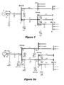
- Figure 1 shows a radially connected power line system provided with a known type of protection scheme based on time graded OC relays.
- a source S feeds power onto a busbar 1 and a line section L1 feeds current from busbar 1 to busbar 2.
- Current flowing in line section L1 near busbar 1 is measured by a current transformer CT, whose signal is passed to a relay R1 for controlling an associated circuit breaker B1, shown by the symbol X.
- the current fed into busbar 2 by section L1 is distributed to two further sections L21 and L22, which are connected to busbar 2 in parallel (though of course each of L21 and L22 considered individually is in series with L1).
- Sections L21 and L22 in turn carry the current to two further busbars 31 and 32, each of which have further line sections L31, L32, L33, etc., connected to them in parallel, and so on to complete the system.
- current is said to radiate from the source end of the system to its far end through the above-described branching paths comprising "radially connected" power line sections.
- each further line section L21, L22, etc. is provided with its own current transformer feeding line section current measurements to protection relays R21, R22, etc., with their associated circuit breakers B21, B22, etc.
- Each relay R1, R21, R22, etc., with its associated circuit breaker and line current transformer (which may be combined with a voltage transformer) is installed proximate, i.e., at or near, the electrically upstream end of each line section, this being the end nearest the source.
- each relay installed at a different position on the system is arranged to operate with a different time delay.
- the sequence from right to left is tf4 ⁇ tf3 ⁇ tf2 ⁇ tf1, with operating times of 0.1 ⁇ 0.5 ⁇ 0.9 ⁇ 1.3 seconds, respectively.
- the relays located in line sections nearer the source S have slower operating times than the relays in sections further away.
- a fault such as F1 in section L1 will cause higher current levels than a fault such as F3 in a section remote from the source S.
- fault currents in section L1 are likely to be so high that they can only be allowed to persist for a short period, which conflicts with the requirement for slower operating times. It will therefore be realised that although it is very easy to select the slower operating times needed to ensure that correct discrimination will be achieved when relays with predetermined time delays are used, their use must be restricted to networks with relatively few serially connected sections.
- An object of this invention is therefore to enable protection relays in radially connected power line systems to make an accelerated operating decision by adapting to the prevailing system and fault conditions, thereby significantly reducing the operating time in situations where previously known types of time graded overcurrent relays cannot offer satisfactory performance.
- the invention can secure the above objective by utilising two types of novel relay functions in conjunction with each other.
- the invention provides a protection system comprising at least one relay installed proximate at least the upstream end of each line section to protect that line section, each relay having an associated circuit breaker, the relays being provided with a first set of accelerated overcurrent functions and a second set of under-current/under-voltage functions, the relays being directional and the first and second sets of functions being time graded in reverse to each other, the first and second sets of functions being distributed amongst the relays such that if an under-current/under-voltage function in a second relay located downstream of a first relay triggers operation of a circuit breaker associated with the second relay, an accelerated overcurrent function in the first relay triggers accelerated operation of a circuit breaker associated with the first relay, thereby to isolate from the power source the line section that the first relay protects.
- those relays which are provided with the second set of functions may additionally possess an autorecloser function.
- the invention envisages distribution of the first and second sets of functions amongst the relays so that each relay has only one function.
- a relay is provided proximate both ends of individual line sections, the relay at the upstream end of each line section being provided with an accelerated overcurrent function and the relay at the downstream end of each line section being provided with an under-current/under-voltage function.
- the invention can also be said to provide a protection system for an electrical power line system comprising radially connected power line sections and a power source for feeding a first electrically upstream one of the line sections connected to the power source, the protection system comprising first and second sets of time-graded relays and their associated circuit breakers, wherein the two sets of relays work together to protect the power line system from fault conditions, the first set of relays and their associated circuit breakers being installed proximate upstream ends of line sections in the power line system to protect the line sections, the second set of relays and their associated circuit breakers being installed proximate the downstream ends of the line sections and being time-graded in reverse to the relays in the first set, each relay in the first set having an overcurrent function operative to trip an associated circuit breaker after a predetermined time delay if the relay detects a fault downstream thereof, each overcurrent function including
- the relays in the second set of relays may also possess an autorecloser function.
- the invention envisages distribution of the first and second sets of functions amongst the relays so that each relay except the most upstream relay has two functions.
- a relay is only provided proximate the upstream end of each line section, each relay being provided with an accelerated overcurrent function and each relay except the relay in the first line section further having a directional under-current and under-voltage function.
- the invention can alternatively be said to provide a protection system for an electrical power line system comprising radially connected power line sections and a power source for feeding a first electrically upstream one of the line sections connected to the power source, the protection system comprising a time-graded relay and an associated circuit breaker installed proximate an upstream end of each line section to protect that line section from fault conditions, each relay having an overcurrent function operative to trip its associated circuit breaker after a predetermined time delay if the relay detects a fault downstream thereof, each overcurrent function including or being associated with an accelerated trip function operative to trip the associated circuit breaker before the predetermined time delay has elapsed if the relay detects operation of a circuit breaker in a downstream adjacent line section, each relay except the relay in the first line section further having a directional under-current and under-voltage function operative to initiate rapid opening of an associated circuit breaker if a fault occurs upstream thereof.
- OC indicates an overcurrent protection function of relays R1, R21, R22, R31, etc., in Figure 1 and R31 in Figures 2a and 2b
- AOC indicates an accelerated overcurrent protection function of relays R1, R21 and R22 in Figures 2a and 2b
- UCV represents an under-current and under-voltage protection function of relays R1', R21', R22' in Figure 2a and of relays R21, R22 and R31 in Figure 2b
- tf1, tf2, tf3 and tf4 are the settings for the forward operating times of the OC and AOC relays at their different locations in Figures 1, 2a and 2b
- tr1 and tr2 are the settings of the reverse operating times of the UCV relays R1' R21' and R22' in Figure 2a and of relays R21, R22 and
- the various relays shown are each associated with a respective circuit breaker B1, B1', B21, B21', etc., and respective current and voltage transformers CT+VT, which supply measurements of line current and line voltage to the relays.
- the current and voltage measurements are for all three phases of the electrical supply to enable the relays to continuously monitor all three phases.
- the circuit breakers operate on all three phases.
- the relays are divided into two sets which work together to protect the power system:
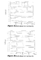
- Figures 2a and 2b illustrate the two main embodiments of the invention. Their basic principles are very similar and Figure 2a is used as an example to demonstrate the first main embodiment. The second main embodiment can be easily explained once the basic principle of the first one is understood.
- the multi-section radially connected power line system Figure 2a has four stages, each consisting of a number of line sections, L1, L21, L22, L31 etc.
- AOC relays R1, R21, R22 and UCV relays R1', R21', R22' are constituted in accordance with the present invention, but OC relays R31, R32, R33 are a known type of overcurrent protection relay.
- Circuit breakers B1, B21, B22, B31, B32, etc., are associated with their respective AOC and OC circuit breakers for the protection of each associated line section as shown in the Figure.
- Circuit breakers B1', B21' and B22' are associated with the UCV relays and are normally used for the protection of their associated busbars 'Y' and 'Z' respectively.
- Invention relays R1, R1', R21, R21', R22 and R22' are responsible for the accelerated protection of their associated line section L1, L21 and L22.
- a first operational set of AOC relays R1, R21 and R22 is installed at or near the upstream ends of the line sections they are protecting (i.e., they are installed at the ends of the line sections which are nearest the source S).
- This first set of relays has two main functions; (i) initial forward fault detection based on the known OC principle and (ii) accelerated operation using the AOC principles of the invention for a fault occurring on its protected section.
- UCV relays R1', R21' and R22' constitute a second operational set and are installed at the downstream (remote or receiving) ends of their respective protected sections L1, L21 and L22. They are responsible for fast detection of fault currents from the direction of the source to the location where the relays are installed. Unlike known OC relays, which rely on increases in current magnitude (overcurrent) for fault detection, the UCV relays rely on decreases in current magnitude (i.e., undercurrent), and voltages (i.e., undervoltage), for fault detection, or directional undercurrent and undervoltage.
- the UCV relays are also equipped with a conventional autorecloser function, this being defined as automatically reclosing their associated circuit breakers B1', B21', B22' following a fixed time delay after a relay has triggered them open.
- the relays R1, R21 and R31 When a fault occurs on section L31, for example at the point 'F3', the relays R1, R21 and R31 will detect the fault due to the changes in current, but the conventional OC relay R31 will operate at a fixed shorter time setting of 0.5 second to trigger its circuit breaker B31, thereby isolating the fault from the other line sections and so preventing relays R1 and R21 from triggering their circuit breakers.
- the time setting of conventional OC relay R31 On line section L31, the time setting of conventional OC relay R31 is thought to be sufficiently short to avoid the damaging effect of high fault current levels.
- each relay can detect voltage and current for all three phases in its respective line section, because it receives line voltage and line current measurements from its associated current and voltage transformers CT+VT.
- the relay R1' can detect a fault F1 using the UCV function of the invention, because the voltage and current at relay R1' drop to near zero on the phase experiencing the fault.
- Relay R1' will therefore trip its associated three-phase circuit breaker B1' instantly (or at least very rapidly), or else after a short delay, as explained below.
- circuit breaker B1' Opening of circuit breaker B1' causes the line section L1 to become open circuit at end Y, but it does not clear the fault on line section L1, because the fault is between relays R1 and R1'.
- the current in the unfaulted or "healthy" phase drops to zero at end X, even though current continues to flow in the faulted phase(s).
- relay R1 Because of this unbalanced current condition, relay R1 will detect that circuit breaker B1' has opened, thereby detecting that the fault is on the protected line section L1. Consequently, instead of waiting for the fixed time delay of 1.3 seconds, R1 instantly opens its associated circuit breaker B1.
- relay R1 is programmed to detect tripping of breaker B1' by relay R1' within a predefined time window from fault inception, and this also facilitates correct detection of remote circuit breaker operation B1' by relay R1. After a fixed time period within which breaker B1 can be tripped, relay R1' will issue a reclosing commend and close circuit breaker B1'.
- Relay R1' may therefore require a time margin to delay its operation and thereby allow for any fault from upstream of the source side of the system.
- the power lines are mostly protected by protection relays based on fast techniques, such as current differential or distance protection schemes.
- the operating time of the upstream protection will be under 0.1 second. This time is the summation of the relay operating time, which is normally under 40 ms, and the breaker operation time, which is about 40 to 60 ms.
- both R21' and R22' will detect the fault and trip their associated breakers B21' and B22' and the healthy phase currents of both lines drop to zero.
- Relay R21 or R22 on the faulted line section can easily detect such a change and trip its associated breaker in accelerated mode but the relay on the healthy line section will give no response since there is no fault detected on its section.
- relay R21' or R22' on the healthy section will issue a reclosing command and close its associated circuit breaker.
- Opening of B21' and B22' will also drop the healthy phase currents at relay R1 to zero if there is no load connected at busbar 'Y', i.e., relay R1 will experience the same condition as it did after B1' tripped. However, R1 will only respond within 0.5 second from inception of the fault because operation of B1' is expected within this time. Breakers B21' and B22' will not operate after the 0.5 second delay (tr2) as shown in the Figure. Therefore, correct operation of R1 can be achieved.
- the relays R21' and R22' can also be set to instant operating mode if there is load present on the busbar 'Y' as shown in Figure 2a. In this mode, the relays will trip their associated circuit breakers B21' and B22' instantly, using their UCV function, instead of delaying for tr2 (0.5 second). By this arrangement, the response speed of the relays protecting L21 and L22 can be further speeded up.
- the second main embodiment of the invention is used in system configurations like that shown in Figure 2b.
- the major difference is that the relays R1', R21' and R22' in Figure 2a are not present in Figure 2b.
- the reason is that for some system configurations, current transformers CT may not be available at the locations for R1', R21' and R22', therefore the UCV function is incorporated into relays R21 and R22, R31, R32 and R33 respectively.
- relay R21 will not only be responsible for OC and AOC protection for line section L21, but also for UCV protection of line section L1.
- R21 and R22 together in Figure 2b will take the role of relay R1' in Figure 2a.
- the UCV functions of relays R31, R32 and R33 will also give corresponding responses for a fault F2 on line section L21 to enable the accelerated tripping function of upstream device R21.
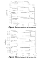
- Figures 3a, 3b, 4a, 4b and 5a, 5b consists of four graphs (1) to (4) showing the responses of relays R1, R1', R21' and R22' respectively to a fault.
- Figures 3a, 4a, 5a show the responses in terms of the three phase currents Ia, Ib and Ic and
- Figures 3b, 4b and 5b show the responses in terms of the three phase voltages Va, Vb and Vc.
- Figures 3a and 3b show the responses of the relays R1, R1', R21' and R22' when they detect a phase 'a' to earth fault F1 on line section L1 as shown in Figure 2a.
- the relays R1, R1', R21' and R22' After inception of the fault at time T 1 , there is a significant increase in the faulted phase current Ia and a drop in faulted phase voltage Va at relay location R1 as shown in Figures 3a(1) and 3b(1).
- the faulted phase current and voltage drop to zero at relay R1' as shown in Figures 3a(2) and 3b(2).
- Relays R1 and R1' will detect the fault based on their OC and UCV functions respectively, and relay R1' which has an instant operating time setting will make a trip decision and open circuit breaker B1' at time T 2 .
- line section L1 becomes open circuit at one end and the currents Ib, Ic of the unfaulted phases 'b' and 'c' drop to zero at relay R1 as shown in Figure 3a(1).
- the phase 'a' to earth fault is not cleared from the line section L1, so R1 detects this unbalanced operating condition and makes a trip decision to open the associated circuit breaker B1 at time T 3 .
- the time delay from the fault inception at time T 1 to the opening of the circuit breaker B1 at time T 3 mainly consists of 2 time periods, t12 and t23.
- the first time period t12 consists of the time period from fault inception to the opening of the circuit breaker B1'. This time period t12 is subdivided into two periods, fault detection by relay R1' and the response time of breaker B1'. Allowing a safety margin, a maximum time period of 0.1 second will guarantee the issue of a tripping signal by relay R1' and opening of the circuit breaker only takes a few power frequency cycles.
- the second time period t23 consists of the time taken for relay R1 to identify the operation of breaker B1', which can be accomplished within one power frequency cycle, plus the response time of the circuit breaker B1, which is approximately 2 to 4 cycles depending on the circuit breaker used. Therefore, the entire operation can be implemented within 0.2 seconds from fault inception. In the known scheme as shown in Figure 1, however, a relay at the location of R1 would not even issue a trip signal until 1.3 seconds had elapsed.
- Figure 4 shows the responses of the invention relays R1, R21, R21' and R22'to a phase 'a' to phase 'b' phase-to-phase fault on line section L21 in Figure 2a.
- R21' which has the fastest operating setting, will operate instantly (if there is a load connected at busbar 'Y') or with a 0.5 second delay (if there is no load connected at busbar 'Y') and subsequently the circuit breaker B21' opens at the time T 2 .
- relays R31, R32 and R33 equipped with the UCV function will operate first to enable the tripping of R21 in accelerated mode.
- Figure 5 show a phase 'a' to earth fault on line section L22 near busbar 'Y'. With a fault in this position, the relays R21' and R22' cannot distinguish between a fault on line section L21 and a fault on line L22, so causing unnecessary operation of breaker B21' if the fault is on line L22. As shown in Figure 5a-b(3) and 5a-b(4), both R21' and R22' detect the undercurrent and undervoltage on phase 'a' since the fault is close to busbar 'Y'. As a result, both relays issue trip signals to open circuit breaker B21' and B22' respectively.
- R22 detects the drop of healthy phase ('b' and 'c') currents and at the same time the fault on phase 'a'. Consequently, R22 operates in accelerated mode to open its associated breaker B22 and the fault is isolated at T 2 . R21, however, will give no response since there is no fault detected on the line section L21. The following reclosing operation by R21' will restore the power supply to line section L21.
- R21' and R22' there are two operation modes for R21' and R22': instant operation, when there is a load connected at 'Y'; and a (0.5 second) delayed operation, when there is no load at 'Y'.
- instant operation when there is a load connected at 'Y'
- a (0.5 second) delayed operation when there is no load at 'Y'.
- R31 to R35 equipped with the UCV function will operate first to enable accelerated operation of breaker B22 by relay R22. After opening of B22, R31, R32, R33, R34 and R35 will automatically reclose their associated circuit breakers.
- the levels of the phase currents shown in the graphs of all the above examples are of nominal values for demonstration purpose.
- the present invention works under all levels of system voltages, source parameters, pre-fault and post-fault load flow conditions.
- the examples show the detection of system unbalanced operating condition and breaker operation based on levels of currents and voltages.
- the invention can also be based on algorithms and criterion expressed in different forms.
- OC Overcurrent
- AOC Accelerated Overcurrent
- UCV Undercurrent and Undervoltage
- the invention can also be easily implemented with conventional relays such as electromechanical relays or static relays, where the levels of the currents and voltages can trigger breaker actions through electromechanical or electronic circuits.
- the devices R21', B21', etc. are described above as relays and circuit breakers. In practice they can take different forms, such as reclosers and sectionalisers which incorporate the UCV function required for practising the invention.
Landscapes
- Emergency Protection Circuit Devices (AREA)
Abstract
Description
Claims (7)
- In an electrical power line system of the type comprising radially connected power line sections (L1, L21, L22, L31, etc.), wherein a first electrically upstream one of the line sections (L1) is connectable to a power source (S), a protection system comprising at least one relay installed proximate at least the upstream end of each line section to protect that line section, each relay (R1, R21, R22, etc./ R1', R21', R22', etc.) having an associated circuit breaker (B1, B21, B22, etc./ B1' B21', B22', etc), the relays being provided with a first set of accelerated overcurrent functions (AOC) and a second set of under-current/under-voltage functions (UCV), the relays being directional and the first and second sets of functions being time graded in reverse to each other, the first and second sets of functions being distributed amongst the relays such that if an under-current/under-voltage function (UCV) in a second relay (R1') located downstream of a first relay (R1) triggers operation of a circuit breaker (B1') associated with the second relay, an accelerated overcurrent function (AOC) in the first relay (R1) triggers accelerated operation of a circuit breaker (B1) associated with the first relay, thereby to isolate from the power source (S) the line section (L1) that the first relay protects.
- The protection system of claim 1, in which the first and second sets of functions (AOC, UCV) are distributed amongst the relays so that each relay has only one function, a relay being provided proximate both ends of individual line sections, the relay (R1, R21, R22, etc.) at the upstream end of each line section (L1, L21, L22, L31, etc.) being provided with an accelerated overcurrent function (AOC) and the relay (R1', R21', R22', etc.) at the downstream end of each line section being provided with an under-current/under-voltage function (UCV).
- The protection system of claim 1 or claim 2, in which relays (R1', R21', R22', etc.) provided with the second set of functions (UCV) additionally possess an autorecloser function.
- The protection system of claim 1, in which the first and second sets of functions (AOC, UCV) are distributed amongst the relays so that each relay except the most upstream relay (R1, Fig. 2b) has two functions, a relay (R1, R21, R22, R31, etc.) being provided proximate only the upstream end of each line section (L1, L21, L22, L31, etc.), each relay being provided with an accelerated overcurrent function (AOC) and each relay except the relay (R1) in the first line section (L1) further having a directional under-current and under-voltage function (UCV).
- A protection system for an electrical power line system comprising radially connected power line sections (L1, L21, L22, L31, etc., Fig. 2a) and a power source (S) for feeding a first electrically upstream one of the line sections (L1) connected to the power source, the protection system comprising first and second sets of time-graded relays (R1, R21, R22, etc./ R1', R21', R22', etc.) and their associated circuit breakers (B1, B21, B22, etc./ B1' B21', B22', etc), wherein the two sets of relays work together to protect the power line system from fault conditions (F1, F2, etc.), the first set of relays (R1, R21, R22, etc.) and their associated circuit breakers (B1, B21, B22, etc.) being installed proximate upstream ends of line sections (L1, L21, L22, L31, etc.) in the power line system to protect the line sections, the second set of relays (R1', R21', R22', etc.) and their associated circuit breakers (B1' B21', B22', etc) being installed proximate the downstream ends of the line sections and being time-graded in reverse to the relays in the first set, each relay (R1) in the first set having an overcurrent function (AOC) operative to trip an associated circuit breaker after a predetermined time delay if the relay (R1) detects a fault downstream thereof, each overcurrent function (AOC) including or being associated with an accelerated trip function operative to trip an associated circuit breaker (B1) before the predetermined time delay has elapsed if the relay (R1) in the first set detects operation of a circuit breaker (B1') associated with a relay (R1') in the second set that is on the same line section (L1) as the relay (R1) in the first set, each relay (R1') in the second set having a directional under-current and under-voltage function (UCV), thereby to initiate rapid opening of an associated circuit breaker (B1') if a fault (F1) occurs upstream thereof.
- A protection system in accordance with claim 5, in which the relays in the second set of relays additionally possess an autorecloser function.
- A protection system for an electrical power line system comprising radially connected power line sections (L1, L21, L22, L31, etc., Fig. 2b) and a power source (S) for feeding a first electrically upstream one of the line sections (L1) connected to the power source, the protection system comprising a time-graded relay (R1, R21, R22, R31, etc.) and an associated circuit breaker (B1, B21, B22, B31, etc.) installed proximate an upstream end of each line section to protect that line section from fault conditions, each relay having an overcurrent function (AOC) operative to trip its associated circuit breaker after a predetermined time delay if the relay detects a fault (F1, F2, etc.) downstream thereof, each overcurrent function (AOC) including or being associated with an accelerated trip function operative to trip the associated circuit breaker before the predetermined time delay has elapsed if the relay detects operation of a circuit breaker in a downstream adjacent line section, each relay except the relay (R1) in the first line section (L1) further having a directional under-current and under-voltage function (UCV) operative to initiate rapid opening of an associated circuit breaker if a fault occurs upstream thereof.
Applications Claiming Priority (2)
| Application Number | Priority Date | Filing Date | Title |
|---|---|---|---|
| GB0210300 | 2002-05-07 | ||
| GB0210300A GB2388482B (en) | 2002-05-07 | 2002-05-07 | Improved power line protection |
Publications (2)
| Publication Number | Publication Date |
|---|---|
| EP1361638A2 true EP1361638A2 (en) | 2003-11-12 |
| EP1361638A3 EP1361638A3 (en) | 2011-07-20 |
Family
ID=9936116
Family Applications (1)
| Application Number | Title | Priority Date | Filing Date |
|---|---|---|---|
| EP03252705A Withdrawn EP1361638A3 (en) | 2002-05-07 | 2003-04-29 | Improved power line protection |
Country Status (5)
| Country | Link |
|---|---|
| US (1) | US7102866B2 (en) |
| EP (1) | EP1361638A3 (en) |
| CN (1) | CN100401609C (en) |
| CA (1) | CA2428287A1 (en) |
| GB (1) | GB2388482B (en) |
Cited By (1)
| Publication number | Priority date | Publication date | Assignee | Title |
|---|---|---|---|---|
| CN104538938A (en) * | 2014-12-02 | 2015-04-22 | 上海交通大学 | Recording-data-based protection safety margin assessment method |
Families Citing this family (18)
| Publication number | Priority date | Publication date | Assignee | Title |
|---|---|---|---|---|
| US7556238B2 (en) * | 2005-07-20 | 2009-07-07 | Fisher Controls International Llc | Emergency shutdown system |
| CN100413171C (en) * | 2005-12-08 | 2008-08-20 | Tcl低压电器(无锡)有限公司 | Regional Selective Interlock |
| US7684900B2 (en) * | 2007-02-20 | 2010-03-23 | Abb Research Ltd. | Adaptive provision of protection function settings of electrical machines |
| WO2009127706A2 (en) * | 2008-04-16 | 2009-10-22 | Fmc Tech Limited | A system and method for locating line faults in a medium voltage network |
| GB0814213D0 (en) * | 2008-08-05 | 2008-09-10 | Rolls Royce Plc | A protection arrangement |
| BR112013010580A8 (en) * | 2010-10-28 | 2017-12-19 | Abb Schweiz Ag | PROTECTION RELAY FOR SENSITIVE EARTH FAULT PROTECTION |
| CN102104246A (en) * | 2011-01-30 | 2011-06-22 | 武汉百叡电力技术有限公司 | Method and device for reducing time limit combination step progression of distribution network relaying protection |
| EP2501008B1 (en) * | 2011-03-15 | 2020-02-19 | ABB Schweiz AG | Protection relay |
| SG189580A1 (en) * | 2011-10-21 | 2013-05-31 | Schneider Electric South East Asia Hq Pte Ltd | An automatic configurable relay |
| RU2603012C2 (en) * | 2012-07-05 | 2016-11-20 | Сименс Акциенгезелльшафт | Device for protection of power compartments and method of protecting power compartments |
| FR2996691B1 (en) * | 2012-10-05 | 2015-11-13 | Schneider Electric Ind Sas | IMPROVED PROTECTION PLAN AGAINST SINGLE PHASE DEFECTS FOR MEDIUM VOLTAGE DISTRIBUTION NETWORKS |
| CN103280786A (en) * | 2013-06-19 | 2013-09-04 | 国家电网公司 | Method for using two sets of line protection devices and one set of reclosure device cooperatively |
| US9590287B2 (en) | 2015-02-20 | 2017-03-07 | Corning Optical Communications Rf Llc | Surge protected coaxial termination |
| LU93345B1 (en) * | 2016-12-08 | 2018-06-08 | Phoenix Contact Gmbh & Co Kg Intellectual Property Licenses & Standards | Protection arrangement of electrical loads and their connection lines against overcurrent |
| CN106841912B (en) * | 2017-01-13 | 2019-01-18 | 浙江大学 | The accurate positioning auxiliary device and method of power cable fault |
| CN112436478B (en) * | 2020-11-12 | 2024-07-05 | 贵州电网有限责任公司 | Automatic reclosing method based on SPSR distribution line and channel-free protection cooperation |
| US11852692B1 (en) * | 2022-12-09 | 2023-12-26 | Milo Group Llc | Electric distribution line ground fault prevention systems using dual parameter monitoring with high sensitivity relay devices |
| US12449465B2 (en) * | 2022-12-09 | 2025-10-21 | Milo Group Llc | Electric distribution line ground fault prevention device using dual parameter high sensitivity monitoring small current reduction with small increase in negative sequence current |
Family Cites Families (9)
| Publication number | Priority date | Publication date | Assignee | Title |
|---|---|---|---|---|
| CH503403A (en) * | 1969-11-26 | 1971-02-15 | Sprecher & Schuh Ag | Overcurrent protection device on an electrical network, with staggered tripping times of their protective relays |
| CH565470A5 (en) * | 1974-06-21 | 1975-08-15 | Sprecher & Schuh Ag | |
| US4006387A (en) * | 1975-09-22 | 1977-02-01 | The United States Of America As Represented By The Secretary Of The Air Force | Low power solid state three-phase overcurrent/undercurrent protection circuit |
| SE409153B (en) * | 1977-11-28 | 1979-07-30 | Asea Ab | RELAY PROTECTION WITH THREE-PHASE RELEASE IN VOLTAGE |
| NL176724C (en) * | 1979-06-11 | 1985-05-17 | Hazemeijer Bv | PROTECTION DEVICE FOR SELECTIVELY SWITCHING OFF NETWORK SECTIONS OF AN ELECTRIC ENERGY DISTRIBUTION NETWORK AND AN ENERGY DISTRIBUTION NETWORK PROVIDED WITH MULTIPLE SELECTIVE PROTECTION DEVICES. |
| GB8727490D0 (en) * | 1987-11-24 | 1987-12-23 | Nat Res Dev | Detecting faults in transmission circuits |
| GB2341737B (en) * | 1998-09-17 | 2003-03-05 | Alstom Uk Ltd | Fault protection apparatus |
| GB9820141D0 (en) * | 1998-09-17 | 1998-11-11 | Alstom Uk Ltd | Improved fault protection scheme |
| CN1167176C (en) * | 2001-08-17 | 2004-09-15 | 清华大学 | Distribution Network Relay Protection and Fault Location System |
-
2002
- 2002-05-07 GB GB0210300A patent/GB2388482B/en not_active Expired - Fee Related
-
2003
- 2003-04-29 EP EP03252705A patent/EP1361638A3/en not_active Withdrawn
- 2003-05-06 CA CA002428287A patent/CA2428287A1/en not_active Abandoned
- 2003-05-07 CN CNB031307221A patent/CN100401609C/en not_active Expired - Fee Related
- 2003-05-07 US US10/431,020 patent/US7102866B2/en not_active Expired - Fee Related
Cited By (2)
| Publication number | Priority date | Publication date | Assignee | Title |
|---|---|---|---|---|
| CN104538938A (en) * | 2014-12-02 | 2015-04-22 | 上海交通大学 | Recording-data-based protection safety margin assessment method |
| CN104538938B (en) * | 2014-12-02 | 2017-08-29 | 上海交通大学 | Protection Safety Margin method based on recorder data |
Also Published As
| Publication number | Publication date |
|---|---|
| GB0210300D0 (en) | 2002-06-12 |
| GB2388482A (en) | 2003-11-12 |
| CN1457125A (en) | 2003-11-19 |
| GB2388482B (en) | 2005-06-15 |
| US20040130839A1 (en) | 2004-07-08 |
| CN100401609C (en) | 2008-07-09 |
| US7102866B2 (en) | 2006-09-05 |
| CA2428287A1 (en) | 2003-11-07 |
| EP1361638A3 (en) | 2011-07-20 |
Similar Documents
| Publication | Publication Date | Title |
|---|---|---|
| US7102866B2 (en) | Power line protection | |
| EP1939999B1 (en) | Circuit protection system | |
| US3873887A (en) | Alternating-current power delivery system | |
| KR960003362B1 (en) | Downed conductor automatic detecting device | |
| US20030142450A1 (en) | Protection of electrical power lines | |
| EP1014530B1 (en) | Electrical power distribution installation for electrical power system | |
| WO2014124660A1 (en) | Method and device for detection of a fault in a protected unit | |
| US5838525A (en) | High speed single-pole trip logic for use in protective relaying | |
| CN100380766C (en) | Direction Comparison Distance Relay System | |
| EP1940000B1 (en) | Circuit protection system | |
| GB2341737A (en) | Fault protection apparatus for use in a time-graded fault protection scheme | |
| US6307723B1 (en) | Parallel-feeder directional overcurrent protection | |
| US4214289A (en) | Stabilizing equipment for power transmission system | |
| US5097380A (en) | Sectionalizer control | |
| RU149438U1 (en) | SHORT-CIRCUIT RELAY PROTECTION | |
| Jonsson et al. | A new protection scheme to prevent mal-trips due to power swings | |
| US2329043A (en) | Protective relaying with discriminative reclosure | |
| US3382410A (en) | Arcing fault detector | |
| US2539416A (en) | Phase-comparison carrier-current relay | |
| Rainin et al. | Improvements of protective characteristics of automatic low-voltage circuit breakers | |
| Guo et al. | Fast Communication-Based Protection and Isolation Schemes | |
| GB2342518A (en) | Overcurrent protection for distribution networks | |
| JPH0469009A (en) | Faulty feeder selector | |
| JPH08317550A (en) | Spot network power receiving device | |
| JPH0159821B2 (en) |
Legal Events
| Date | Code | Title | Description |
|---|---|---|---|
| PUAI | Public reference made under article 153(3) epc to a published international application that has entered the european phase |
Free format text: ORIGINAL CODE: 0009012 |
|
| AK | Designated contracting states |
Kind code of ref document: A2 Designated state(s): AT BE BG CH CY CZ DE DK EE ES FI FR GB GR HU IE IT LI LU MC NL PT RO SE SI SK TR |
|
| AX | Request for extension of the european patent |
Extension state: AL LT LV MK |
|
| RAP1 | Party data changed (applicant data changed or rights of an application transferred) |
Owner name: AREVA T&D SA |
|
| RAP1 | Party data changed (applicant data changed or rights of an application transferred) |
Owner name: AREVA T&D SA |
|
| RAP1 | Party data changed (applicant data changed or rights of an application transferred) |
Owner name: AREVA T&D SAS |
|
| RAP1 | Party data changed (applicant data changed or rights of an application transferred) |
Owner name: AREVA T&D SAS |
|
| PUAL | Search report despatched |
Free format text: ORIGINAL CODE: 0009013 |
|
| AK | Designated contracting states |
Kind code of ref document: A3 Designated state(s): AT BE BG CH CY CZ DE DK EE ES FI FR GB GR HU IE IT LI LU MC NL PT RO SE SI SK TR |
|
| AX | Request for extension of the european patent |
Extension state: AL LT LV MK |
|
| RAP1 | Party data changed (applicant data changed or rights of an application transferred) |
Owner name: SCHNEIDER ELECTRIC ENERGY FRANCE Owner name: AREVA T&D SAS |
|
| AKX | Designation fees paid |
Designated state(s): AT BE BG CH CY CZ DE DK EE ES FI FR GB GR HU IE IT LI LU MC NL PT RO SE SI SK TR |
|
| RAP1 | Party data changed (applicant data changed or rights of an application transferred) |
Owner name: SCHNEIDER ELECTRIC ENERGY FRANCE Owner name: ALSTOM GRID SAS |
|
| STAA | Information on the status of an ep patent application or granted ep patent |
Free format text: STATUS: THE APPLICATION IS DEEMED TO BE WITHDRAWN |
|
| 18D | Application deemed to be withdrawn |
Effective date: 20120121 |