EP1361430A2 - Gas concentration sensor - Google Patents
Gas concentration sensor Download PDFInfo
- Publication number
- EP1361430A2 EP1361430A2 EP03251861A EP03251861A EP1361430A2 EP 1361430 A2 EP1361430 A2 EP 1361430A2 EP 03251861 A EP03251861 A EP 03251861A EP 03251861 A EP03251861 A EP 03251861A EP 1361430 A2 EP1361430 A2 EP 1361430A2
- Authority
- EP
- European Patent Office
- Prior art keywords
- transmitting
- acoustic wave
- reflection wall
- gas
- gas concentration
- Prior art date
- Legal status (The legal status is an assumption and is not a legal conclusion. Google has not performed a legal analysis and makes no representation as to the accuracy of the status listed.)
- Withdrawn
Links
- 238000005259 measurement Methods 0.000 claims abstract description 73
- 230000002093 peripheral effect Effects 0.000 claims abstract description 20
- 230000005540 biological transmission Effects 0.000 claims abstract description 14
- 239000000446 fuel Substances 0.000 claims description 28
- 238000002485 combustion reaction Methods 0.000 claims description 4
- 239000007789 gas Substances 0.000 description 117
- 239000007788 liquid Substances 0.000 description 39
- XLYOFNOQVPJJNP-UHFFFAOYSA-N water Chemical compound O XLYOFNOQVPJJNP-UHFFFAOYSA-N 0.000 description 17
- 230000005484 gravity Effects 0.000 description 15
- 238000011084 recovery Methods 0.000 description 10
- 238000009833 condensation Methods 0.000 description 8
- 230000005494 condensation Effects 0.000 description 8
- IJGRMHOSHXDMSA-UHFFFAOYSA-N Atomic nitrogen Chemical compound N#N IJGRMHOSHXDMSA-UHFFFAOYSA-N 0.000 description 4
- 230000002238 attenuated effect Effects 0.000 description 3
- 239000002828 fuel tank Substances 0.000 description 3
- 230000035945 sensitivity Effects 0.000 description 3
- 229910001873 dinitrogen Inorganic materials 0.000 description 2
- 230000000694 effects Effects 0.000 description 2
- 239000000463 material Substances 0.000 description 2
- 230000001902 propagating effect Effects 0.000 description 2
- 238000010926 purge Methods 0.000 description 2
- 239000004215 Carbon black (E152) Substances 0.000 description 1
- 230000002411 adverse Effects 0.000 description 1
- 239000002131 composite material Substances 0.000 description 1
- 238000001514 detection method Methods 0.000 description 1
- 230000008014 freezing Effects 0.000 description 1
- 238000007710 freezing Methods 0.000 description 1
- 229930195733 hydrocarbon Natural products 0.000 description 1
- 150000002430 hydrocarbons Chemical class 0.000 description 1
- 238000000034 method Methods 0.000 description 1
- 229910052757 nitrogen Inorganic materials 0.000 description 1
- 230000000644 propagated effect Effects 0.000 description 1
Images



Classifications
-
- G—PHYSICS
- G01—MEASURING; TESTING
- G01N—INVESTIGATING OR ANALYSING MATERIALS BY DETERMINING THEIR CHEMICAL OR PHYSICAL PROPERTIES
- G01N29/00—Investigating or analysing materials by the use of ultrasonic, sonic or infrasonic waves; Visualisation of the interior of objects by transmitting ultrasonic or sonic waves through the object
- G01N29/22—Details, e.g. general constructional or apparatus details
- G01N29/222—Constructional or flow details for analysing fluids
-
- G—PHYSICS
- G01—MEASURING; TESTING
- G01N—INVESTIGATING OR ANALYSING MATERIALS BY DETERMINING THEIR CHEMICAL OR PHYSICAL PROPERTIES
- G01N29/00—Investigating or analysing materials by the use of ultrasonic, sonic or infrasonic waves; Visualisation of the interior of objects by transmitting ultrasonic or sonic waves through the object
- G01N29/02—Analysing fluids
- G01N29/024—Analysing fluids by measuring propagation velocity or propagation time of acoustic waves
-
- G—PHYSICS
- G01—MEASURING; TESTING
- G01N—INVESTIGATING OR ANALYSING MATERIALS BY DETERMINING THEIR CHEMICAL OR PHYSICAL PROPERTIES
- G01N2291/00—Indexing codes associated with group G01N29/00
- G01N2291/01—Indexing codes associated with the measuring variable
- G01N2291/011—Velocity or travel time
-
- G—PHYSICS
- G01—MEASURING; TESTING
- G01N—INVESTIGATING OR ANALYSING MATERIALS BY DETERMINING THEIR CHEMICAL OR PHYSICAL PROPERTIES
- G01N2291/00—Indexing codes associated with group G01N29/00
- G01N2291/01—Indexing codes associated with the measuring variable
- G01N2291/015—Attenuation, scattering
-
- G—PHYSICS
- G01—MEASURING; TESTING
- G01N—INVESTIGATING OR ANALYSING MATERIALS BY DETERMINING THEIR CHEMICAL OR PHYSICAL PROPERTIES
- G01N2291/00—Indexing codes associated with group G01N29/00
- G01N2291/02—Indexing codes associated with the analysed material
- G01N2291/021—Gases
- G01N2291/0212—Binary gases
-
- G—PHYSICS
- G01—MEASURING; TESTING
- G01N—INVESTIGATING OR ANALYSING MATERIALS BY DETERMINING THEIR CHEMICAL OR PHYSICAL PROPERTIES
- G01N2291/00—Indexing codes associated with group G01N29/00
- G01N2291/02—Indexing codes associated with the analysed material
- G01N2291/021—Gases
- G01N2291/0217—Smoke, combustion gases
-
- G—PHYSICS
- G01—MEASURING; TESTING
- G01N—INVESTIGATING OR ANALYSING MATERIALS BY DETERMINING THEIR CHEMICAL OR PHYSICAL PROPERTIES
- G01N2291/00—Indexing codes associated with group G01N29/00
- G01N2291/02—Indexing codes associated with the analysed material
- G01N2291/028—Material parameters
- G01N2291/02809—Concentration of a compound, e.g. measured by a surface mass change
-
- G—PHYSICS
- G01—MEASURING; TESTING
- G01N—INVESTIGATING OR ANALYSING MATERIALS BY DETERMINING THEIR CHEMICAL OR PHYSICAL PROPERTIES
- G01N2291/00—Indexing codes associated with group G01N29/00
- G01N2291/04—Wave modes and trajectories
- G01N2291/045—External reflections, e.g. on reflectors
-
- G—PHYSICS
- G01—MEASURING; TESTING
- G01N—INVESTIGATING OR ANALYSING MATERIALS BY DETERMINING THEIR CHEMICAL OR PHYSICAL PROPERTIES
- G01N2291/00—Indexing codes associated with group G01N29/00
- G01N2291/10—Number of transducers
- G01N2291/101—Number of transducers one transducer
Definitions
- the present invention relates to a gas concentration sensor for detecting the concentration of a specific gas component of a gas under measurement on the basis of a propagation time between transmission of an acoustic wave and reception of the acoustic wave, and more particular to a gas concentration sensor that minimizes gas concentration measurement errors and measurement inability states caused by the adhesion of standing liquid within the sensor.
- fuel vapor such as purge gas
- fuel vapor such as purge gas
- control of air-fuel ratio is very important, in order to minimize the content of harmful gas, such as CO, HC (hydrocarbon), and NO x , in exhaust gas, which increases with deviation of an air-fuel ratio from a theoretical ideal value.
- harmful gas such as CO, HC (hydrocarbon), and NO x
- the concentration of fuel vapor is measured with high accuracy, and the amount of fuel vapor and the amount of fuel injected from the injector are controlled on the basis of the measured values.
- Gas concentration sensors have hitherto been used as means for detecting concentration of fuel vapor; and an example of such a conventional gas concentration sensor is an ultrasonic wave gas concentration sensor, which is currently under development.
- the ultrasonic wave gas concentration sensor can determine the concentration of fuel vapor on the basis of a propagation time between transmission of an acoustic wave and reception of the reflected acoustic wave.
- Such an ultrasonic wave gas concentration sensor is shown in Japanese Patent Application Laid-Open ( kokai ) No. H7-209259.
- This publication proposes a structure for mounting a gas concentration sensor for a vehicle, which structure enables accurate and efficient detection of gas concentration even when liquid is produced within the sensor as a result of condensation of fuel vapor or water vapor.
- gas holes inflow and outflow holes 15 and 16
- gas holes which allow inflow and outflow of gas in the state in which the gas concentration sensor is mounted on a vehicle or an engine, are disposed in a lowermost portion in a measurement chamber 13 provided between an ultrasonic wave transmitting-receiving element 11 for transmitting and receiving an ultrasonic wave and a reflection wall 12.
- standing liquid 14 adheres to the ultrasonic wave transmitting-receiving element 11, the standing liquid 14 hinders transmission and reception of an ultrasonic wave, thereby lowering, for example, the output, receiving sensitivity, and transmitting-receiving efficiency of the ultrasonic wave transmitting-receiving element 11.
- standing liquid refers to liquid generated as a result of condensation of fuel vapor, water vapor, etc. within or outside the sensor and standing within the sensor (within the measurement chamber) without being drained out of the sensor.
- the ultrasonic wave received by the ultrasonic wave transmitting-receiving element 11 includes not only components reflected by the reflection wall 12, but also those reflected by the surface of the standing liquid 14.
- the ultrasonic wave transmission distance would be a distance L2, which is shorter than a true distance L1.
- the gas concentration would be calculated as being lower than a true value, with the result that an accurate value of the gas concentration cannot be obtained.
- a reflection wave to be received by an ultrasonic wave element is attenuated by influences attributed to the material of a sensor housing, the shape of a wall surface of a measurement chamber in which the ultrasonic wave propagates, the surface shape of a reflection wall, the propagation distance of the ultrasonic wave, the frequency of the ultrasonic wave, the gas pressure, the gas temperature, and other factors.
- a threshold level is set by use of a portion of a received wave in order to change the threshold level in accordance with the amplitude of the received wave, and propagation time is measured accurately by use of the changed threshold level.
- a portion of a received wave to be used for setting the threshold level contains an improper-path wave propagated along a path other than a proper path, the resulting threshold level would deviate from the proper value, thereby causing errors in measuring the concentration of a gas.
- An object of the present invention is to provide a gas concentration sensor capable of measuring the concentration of a gas accurately and efficiently.
- a gas concentration sensor comprising: a measurement chamber for measuring a concentration of a specific gas in gas under measurement; an inflow path for allowing inflow of the gas under measurement to the measurement chamber and an outflow path for allowing outflow of the gas under measurement from the measurement chamber; a reflection wall disposed on one end surface of the measurement chamber and adapted to reflect an acoustic wave; and an acoustic wave transmitting-receiving element having, on the other end surface of the measurement chamber, which surface opposes the reflection wall, a transmitting-receiving surface adapted to transmit an acoustic wave toward the reflection wall and receive the acoustic wave reflected from the reflection wall, whereby the concentration of the specific gas in the gas under measurement is detected on the basis of a propagation time between transmission of the acoustic wave and reception of the reflected acoustic wave.
- the sensor is characterized in that when a predetermined member having the sensor attached thereto is placed in a horizontal plane, the transmitting-receiving surface faces downward; and a peripheral portion of the reflection wall includes a recess receded toward a back surface of the reflection wall.
- a gas concentration sensor comprising: a measurement chamber for measuring a concentration of a specific gas in gas under measurement; an inflow path for allowing inflow of the gas under measurement to the measurement chamber and an outflow path for allowing outflow of the gas under measurement from the measurement chamber; a reflection wall disposed on one end surface of the measurement chamber and adapted to reflect an acoustic wave; an acoustic wave transmitting-receiving element having, on the other end surface of the measurement chamber, which surface opposes the reflection wall, a transmitting-receiving surface adapted to transmit an acoustic wave toward the reflection wall and receive the acoustic wave reflected from the reflection wall, whereby the concentration of the specific gas in the gas under measurement is detected on the basis of a propagation time between transmission of the acoustic wave and reception of the reflected acoustic wave.
- the sensor is characterized in that when a predetermined member having the sensor attached thereto is placed in a horizontal plane, the transmitting-receiving surface assumes a horizontal posture facing downward; and a peripheral portion of the reflection wall includes a recess receded toward a back surface of the reflection wall.
- a gas concentration sensor comprising: a measurement chamber for measuring a concentration of a specific gas in gas under measurement; an inflow path for allowing inflow of the gas under measurement to the measurement chamber and an outflow path for allowing outflow of the gas under measurement from the measurement chamber; a reflection wall disposed on one end surface of the measurement chamber and adapted to reflect an acoustic wave; and an acoustic wave transmitting-receiving element having, on the other end surface of the measurement chamber, which surface opposes the reflection wall, a transmitting-receiving surface adapted to transmit an acoustic wave toward the reflection wall and receive the acoustic wave reflected from the reflection wall, whereby the concentration of the specific gas in the gas under measurement is detected on the basis of a propagation time between transmission of the acoustic wave and reception of the reflected acoustic wave.
- the sensor is characterized in that when a predetermined member having the sensor attached thereto is placed in a horizontal plane, the transmitting-receiving surface is inclined with respect to a horizontal plane by a predetermined angle and faces downward; and a peripheral portion of the reflection wall includes a recess receded toward a back surface of the reflection wall.
- the outflow path or the inflow path communicate with the recess at a predetermined position lower than a front surface of the reflection wall.
- the outflow path or the inflow path communicates with a region including a lowermost position of the recess.
- a bottom surface of the recess is inclined by a predetermined angle with respect to the front surface of the reflection wall.
- the acoustic wave transmitting-receiving element has a second recess which is formed in a peripheral portion of the acoustic wave transmitting-receiving element and receded toward the back surface of the transmitting-receiving surface.
- the specific gas may be fuel vapor generated for use in an internal combustion engine.
- a gas concentration sensor includes a measurement chamber (denoted by reference numeral 3 in Fig. 1) for measuring a concentration of a specific gas in gas under measurement; an inflow path (reference numeral 5 in Fig. 1) for allowing inflow of the gas under measurement to the measurement chamber and an outflow path (reference numeral 6 in Fig. 1) for allowing outflow of the gas under measurement from the measurement chamber; a reflection wall (reference numeral 2 in Fig. 1) disposed on one end surface of the measurement chamber and adapted to reflect an acoustic wave; and an acoustic wave transmitting-receiving element (reference numeral 1 in Fig.
- a transmitting-receiving surface (reference numeral 1' in Fig. 1) adapted to transmit an acoustic wave toward the reflection wall and receive the acoustic wave reflected from the reflection wall.
- the concentration of the specific gas in the gas under measurement is detected on the basis of a propagation time between transmission of the acoustic wave and reception of the reflected acoustic wave.
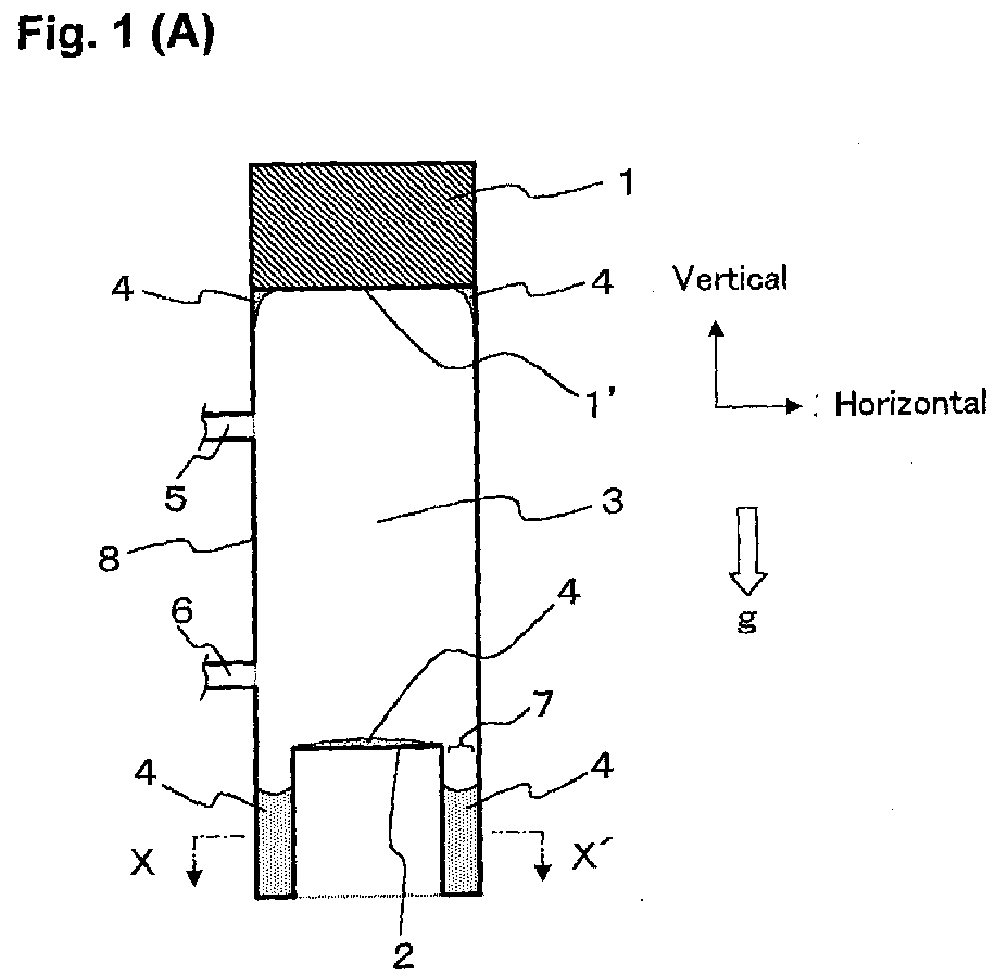
- Fig. 1 is a cross-sectional view schematically showing the configuration of a gas concentration sensor according to Embodiment 1 of the present invention, wherein Fig. 1(A) is a longitudinal cross-sectional view, and Fig. 1(B) is a cross-sectional view taken along a transverse direction (line X-X') in Fig. 1(A).
- standing liquid 4 does not constitute any portion of the configuration of the gas concentration sensor (the same applies all the embodiments).
- the present gas concentration sensor is a sensor for detecting the concentration of a specific gas in gas under measurement on the basis of a propagation time (sonic speed) between transmission of an acoustic wave and reception of the acoustic wave.
- the gas concentration sensor includes an ultrasonic wave transmitting-receiving element 1, a reflection wall 2, a measurement chamber 3, an inflow path 5, an outflow path 6, a recess 7, and a container 8.
- An arrow g indicates the direction of gravity.
- the ultrasonic wave transmitting-receiving element 1 is disposed on an end surface (hereinafter called another surface) of the measurement chamber 3, which surface opposes the reflection wall 2.
- the ultrasonic wave transmitting-receiving element 1 is adapted to transmit an ultrasonic wave toward the reflection wall 2 and receive the ultrasonic wave reflected from the reflection wall 2.
- the gas concentration sensor is attached to a predetermined member placed in a horizontal plane
- the ultrasonic wave transmitting-receiving element 1 is attached to an upper end portion of the container 8 with its transmitting-receiving surface 1' facing downward (toward the ground), and a junction between the ultrasonic wave transmitting-receiving element 1 and the container 8 is sealed in such a manner that gas does not leak from the measurement chamber 3.
- the reflection wall 2 is disposed in the vicinity of a center of a bottom of the container 8, which bottom opposes the transmitting-receiving surface 1' of the ultrasonic wave transmitting-receiving element 1 and whose inner wall surface is flat and substantially parallel to the transmitting-receiving surface 1' to reflect an ultrasonic wave transmitted from the ultrasonic transmitting-receiving element 1.
- the measurement chamber 3 is a space which is surrounded by the container 8 and in which the concentration of a specific gas in gas under measurement is to be measured between the ultrasonic wave transmitting-receiving element 1 and the reflection wall 2.
- the inflow path 5 is connected to the side wall of the container 8 at a position lower than the ultrasonic wave transmitting-receiving element 1 and higher than the inner wall surface of the reflection wall 2.
- the inflow path 5 serves as a flow passageway allowing inflow of gas under measurement to the measurement chamber 3.
- the outflow path 6 is connected to the side wall of the container 8 at a position lower than the ultrasonic wave transmitting-receiving element 1 and higher than the inner wall surface of the reflection wall 2.
- the outflow path 6 serves as a flow passageway allowing outflow of the gas under measurement from the measurement chamber 3.
- the recess 7 is a gutter-shaped portion formed in a peripheral portion of the reflection wall 2 and receded toward the back surface of the reflection wall 2, i.e. in a direction away from the transmitting-receiving element 1.
- the container 8 is a generally cylindrical, tubular vessel.
- the gas concentration sensor is placed on a predetermined member of, for example, an engine or a vehicle in such a manner that the transmitting-receiving surface 1' of the ultrasonic wave transmitting-receiving element 1 assumes a horizontal posture facing downward. Therefore, the bulk of standing liquid 4 adhering to the vicinity of a peripheral edge of the transmitting-receiving surface 1' by surface tension flows down to a lower portion of the measurement chamber 3 under the force of gravity, thereby eliminating the fear that a large amount of standing liquid 4 might stand at a peripheral portion of the ultrasonic wave transmitting-receiving element 1.
- the recess 7 is provided in the peripheral portion of the reflection wall 2, the bulk of the standing liquid 4 adhering to the front surface of the reflection wall 2 flows down to the recess 7 around the reflection wall 2 under the force of gravity, thereby eliminating the fear that a large amount of standing liquid 4 might stand on the surface of the reflection wall 2.
- the recess 7 is formed in the peripheral portion of the reflection wall 2, mixing of a normally received wave (a wave reflected from the reflection wall 2) and a reflected wave propagating trough an improper path (a wave reflected from the recess 7, also called an improper-path wave) can be avoided. Therefore, the received wave and the reflected wave propagating through an improper path can be separated from each other by means of, for example, an analog switch (Fig. 11).
- FIG. 2 is a fragmentary cross-sectional view schematically showing the configuration of a bottom portion, and its vicinity, of a gas concentration sensor according to Embodiment 2 of the present invention.
- An arrow g indicates the direction of gravity.
- the present gas concentration sensor is identical in configuration with that of Embodiment 1, except for the position of the outflow path 6.
- the outflow path 6 is connected to the recess 7 of the container at a position below (lower than) the front surface of the reflection wall 2.
- Embodiment 2 because the outflow path 6 is located below the reflection wall 2, the standing liquid 4 exceeding the outflow path 6 flows into the outflow path 6 under the force of gravity even when a large amount of standing liquid 4 flows into the recess 7. As a result, the fear that standing liquid 4 might stand in an overflow state on the front surface of the reflection wall 2 is eliminated.
- FIG. 3 is a fragmentary cross-sectional view schematically showing the configuration of a bottom portion, and its vicinity, of a gas concentration sensor according to Embodiment 3 of the present invention.
- An arrow g indicates the direction of gravity.
- the present gas concentration sensor is identical in configuration with that of Embodiment 1, except for the position of the outflow path 6.
- the outflow path 6 is connected to a lowermost position of the recess 7 of the container including a bottom surface of the recess 7.
- Embodiment 3 because the outflow path 6 is located at the lowermost position of the recess 7, the bulk of the standing liquid 4 standing in the recess 7 flows into the outflow path 6 under the force of gravity, thereby eliminating the fear that a large amount of standing liquid 4 might stand within the recess 7.
- Fig. 4 is a fragmentary cross-sectional view schematically showing the configuration of a bottom portion, and its vicinity, of a gas concentration of Embodiment 4 of the present invention.
- An arrow g indicates the direction of gravity.
- the present gas concentration sensor is identical in configuration with that of Embodiment 1, except for the position of the outflow path 6 and the configuration of the recess 7.
- the outflow path 6 is connected to a lowermost position of the recess 7 of the container including a bottom surface of the recess 7.
- a bottom wall 7' of the recess 7 is not parallel to an inner wall surface of the reflection wall 2, but slants toward the outflow path 6 in the lowermost position.
- Embodiment 4 because the bottom wall 7' of the recess 7 slants toward the outflow path 6, the bulk of the standing liquid 4 adhering to the bottom wall 7' of the recess 7 by surface tension flows and gathers to the outflow path 6 under the force of gravity, thereby eliminating the fear that a large amount of standing liquid 4 might stand in the bottom wall 7' of the recess 7.
- Fig. 5 is a cross-sectional view schematically showing the configuration of a gas concentration sensor according to Embodiment 5 of the present invention.
- Fig. 6 is a fragmentary cross-sectional view schematically showing the configuration of a bottom portion, and its vicinity, of the gas concentration according to Embodiment 5 of the present invention.
- An arrow g indicates the direction of gravity.
- the present gas concentration sensor is identical in configuration with that of Embodiment 4, but differs in posture from that of Embodiment 4.
- the gas concentration sensor assumes such a posture that the outflow path 6 assumes the lowermost position to thereby incline each of the inner wall surface of the reflection wall 2 and the transmitting-receiving surface 1' of the ultrasonic wave transmitting-receiving element 1 with respect to a horizontal plane.
- Embodiment 5 because the transmitting-receiving surface 1' of the ultrasonic wave transmitting-receiving element 1 is inclined with respect to a horizontal plane, the bulk of the standing liquid (not shown in Fig. 5) adhering to the vicinity of the periphery of the transmitting-receiving surface 1' by surface tension flows down to a lower portion of the measurement chamber 3 under the force of gravity, thereby eliminating the fear that a large amount of standing liquid might stand at the peripheral portion of the ultrasonic wave transmitting-receiving element 1.
- the inner wall surface of the reflection wall 2 is inclined with respect to a horizontal plane, the bulk of the standing liquid 4 adhering to the inner wall surface of the reflection wall 2 by surface tension flows down to the recess 7 under the force of gravity, thereby eliminating the fear that a large amount of standing liquid might stand on the inner wall surface of the reflection wall 2.
- the bottom wall 7' of the recess 7 is not parallel to the reflection wall 2, the bulk of the standing liquid 4 adhering to the bottom wall 7' of the recess 7 flows down to the outflow path 6 under the force of gravity, thereby eliminating the fear that a large amount of standing liquid might stand on the bottom wall 7' of the recess 7.
- the outflow path 6 is disposed in a lowermost position of the recess 7, the bulk of the standing liquid 4 standing in the recess 7 flows down to the outflow path 6 under the force of gravity, thereby eliminating the fear that a large amount of standing liquid might stand in the recess 7.
- Fig. 7 is a graph showing a flow-rate dependency of output recovery time in the case of the gas concentration sensor according to Embodiment 5 of the present invention
- Fig. 8 is a graph showing a flow-rate dependency of output recovery time in the case of the conventional gas concentration sensor.
- the gas concentration sensors compared here were the gas concentration sensor of Embodiment 5 shown in Fig. 5 and the conventional gas concentration sensor shown in Fig. 10. These two gas concentration sensors were identical with each other in terms of the material of the ultrasonic wave transmitting-receiving element and that of the container, and were identical with each other in terms of the following parameters: the diameter of the container, the distance between the transmitting-receiving surface of the ultrasonic wave transmitting-receiving element and the reflection wall, and the size of the inflow and outflow paths.
- output recovery time refers to a period of time defined as follows. First, the flow passage of the sensor is fully filled with water, and subsequently, nitrogen gas is supplied from the inflow path at a constant flow rate. A period of time from a point in time when the supply of the nitrogen gas is started and a point in time when the output level of the sensor is recovered (when the output attains the same level as that in the state where water is not present within the flow passage of the sensor) is measured as an output recovery time.
- Figs. 7 and 8 each show output recovery time [sec] for each gas concentration sensor with respect to the flow of nitrogen [L/min], where ⁇ L ⁇ represents liters.
- the test results for the conventional gas concentration sensor shown Fig. 8 indicate that variation of output recovery time is large, particularly on the low-flow side (lower than around 20 [L/min]) and that, in some cases, the output is not recovered even after passage of a considerably long time.
- the sensor was disassembled, and the surfaces of the ultrasonic wave transmitting-receiving element 11 and the reflection wall 12 were examined. This examination confirmed that a large amount of water was standing on these surfaces (See Fig. 10).
- the results for the gas concentration sensor according to Embodiment 5 shown in Fig. 7 indicate that variation in output recovery time was small across the entire range of flow rate. Further, the sensor was disassembled, and the surfaces of the ultrasonic wave transmitting-receiving element 1 and the reflection wall 2 were examined. This examined confirmed that no standing water was present (See Fig. 5).
- the conventional gas concentration sensor and the gas concentration sensor of Embodiment 5 differ greatly in the amount of standing water within the container. Therefore, the gas concentration sensor of Embodiment 5, which is substantially free of standing of water, is expected to exhibit its proper performance in the case where liquid generated as a result of condensation of fuel vapor, water, etc. is apt to stand within the sensor (e.g., when the sensor is cold before startup of the engine), or in the case where water vapor, etc. is apt to condense and hence water or other liquid stands within the sensor (e.g., when the sensor cools as a result of stoppage of the engine).
- the gas concentration sensor of Embodiment 5 allows outflow of a sufficient amount of liquid generated as a result of condensation of fuel vapor, water, etc. even in the absence of flow of gas such as, for example, when the engine is stopped, and freezing of water, etc. within the sensor can be avoided. Therefore, the present gas concentration sensor is expected to exhibit its proper performance when employed in a motor vehicle climatized to cold regions.
- Fig. 9 is a fragmentary cross-sectional view schematically showing the configuration of an ultrasonic wave transmitting-receiving element, and its vicinity, of a gas concentration sensor according to Embodiment 6 of the present invention.
- An arrow g indicates the direction of gravity.
- the present gas concentration sensor is identical in configuration with those of Embodiments 1 to 5, but differs in that the container 8 has, in addition to the recess formed in the peripheral portion of the reflection wall, a recess 9 receded in the peripheral portion of the ultrasonic wave transmitting-receiving element 1 toward a back surface of the transmitting-receiving surface.
- the peripheral portion of the ultrasonic wave transmitting-receiving element 1 also has the recess
- the wall surface of the container 8 and the transmitting-receiving surface 1' of the ultrasonic wave transmitting-receiving element 1 define no angle therebetween, so that standing liquid (not shown) can hardly adhere to the peripheral portion of the transmitting-receiving surface 1'.
- the acoustic wave to be transmitted and received is an ultrasonic wave.
- the acoustic wave may be an acoustic wave other than an ultrasonic wave.
- a single composite element serves to transmit and receive an acoustic wave, two separate elements may be provided to serve for transmission and reception of an acoustic wave, respectively.
- the positional relationship between the above-defined inflow path 5 and the outflow path 6 may be reversed.
- the senor is free of a drop in output of the acoustic wave transmitting-receiving element, a drop in receiving sensitivity, and a drop in transmitting-receiving efficiency; and measurement results are not accompanied by errors caused by variation of the acoustic wave transmission distance. Accordingly, concentration of a specific gas in gas under measurement can be detected accurately and efficiently.
Landscapes
- Physics & Mathematics (AREA)
- Acoustics & Sound (AREA)
- Health & Medical Sciences (AREA)
- Life Sciences & Earth Sciences (AREA)
- Chemical & Material Sciences (AREA)
- Analytical Chemistry (AREA)
- Biochemistry (AREA)
- General Health & Medical Sciences (AREA)
- General Physics & Mathematics (AREA)
- Immunology (AREA)
- Pathology (AREA)
- Investigating Or Analyzing Materials By The Use Of Ultrasonic Waves (AREA)
Abstract
Description
Claims (8)
- A gas concentration sensor comprising:wherein the sensor is adapted such that, in use, the transmitting-receiving surface faces downward; anda measurement chamber for measuring the concentration of a specific gas component in a gas under measurement;an inflow path for allowing inflow of the gas under measurement to the measurement chamber and an outflow path for allowing outflow of the gas under measurement from the measurement chamber;a reflection wall disposed on one end surface of the measurement chamber and adapted to reflect an acoustic wave; andan acoustic wave transmitting-receiving element having, on the other end surface of the measurement chamber, which surface opposes the reflection wall, a transmitting-receiving surface adapted to transmit an acoustic wave toward the reflection wall and receive the acoustic wave reflected from the reflection wall, whereby the concentration of the specific gas component in the gas under measurement is detected on the basis of a propagation time between transmission of the acoustic wave and reception of the reflected acoustic wave,
a peripheral portion of the reflection wall includes a recess receded away from the transmitting-receiving surface. - A gas concentration sensor according to claim1, wherein the transmitting-receiving surface, which faces downward, assumes a substantially horizontal posture.
- A gas concentration sensor according to claim 1, wherein the transmitting-receiving surface, which faces downward, is inclined with respect to a horizontal plane by a predetermined angle.
- A gas concentration sensor according to any one of claims 1 to 3, wherein the outflow path or the inflow path communicates with the recess at a predetermined position lower than a front surface of the reflection wall.
- A gas concentration sensor according to any one of claims 1 to 4, wherein the outflow path or the inflow path communicates with a region including a lowermost position of the recess.
- A gas concentration sensor according to any one of claims 1 to 5, wherein a bottom surface of the recess is inclined by a predetermined angle with respect to the front surface of the reflection wall.
- A gas concentration sensor according to any one of claims 1 to 6, wherein the acoustic wave transmitting-receiving element has a second recess which is formed in a peripheral portion of the acoustic wave transmitting-receiving element and receded rearwardly from the transmitting-receiving surface.
- A gas concentration sensor according to any one of claims 1 to 7, wherein the specific gas component is fuel vapor generated for use in an internal combustion engine.
Applications Claiming Priority (2)
| Application Number | Priority Date | Filing Date | Title |
|---|---|---|---|
| JP2002133059A JP3740088B2 (en) | 2001-09-20 | 2002-05-08 | Gas concentration sensor |
| JP2002133059 | 2002-05-08 |
Publications (2)
| Publication Number | Publication Date |
|---|---|
| EP1361430A2 true EP1361430A2 (en) | 2003-11-12 |
| EP1361430A3 EP1361430A3 (en) | 2005-05-04 |
Family
ID=29244114
Family Applications (1)
| Application Number | Title | Priority Date | Filing Date |
|---|---|---|---|
| EP03251861A Withdrawn EP1361430A3 (en) | 2002-05-08 | 2003-03-25 | Gas concentration sensor |
Country Status (2)
| Country | Link |
|---|---|
| US (1) | US6892566B2 (en) |
| EP (1) | EP1361430A3 (en) |
Cited By (2)
| Publication number | Priority date | Publication date | Assignee | Title |
|---|---|---|---|---|
| WO2011004286A1 (en) | 2009-07-07 | 2011-01-13 | Koninklijke Philips Electronics N. V. | Multifunction sensor system and method comprising an ultrasonic sensor for supervising room conditions |
| WO2022060320A1 (en) | 2020-09-15 | 2022-03-24 | T.C. Piri Reis Universitesi | Mach-zehnder interferometer based ultrasound concentration sensor for liquid mixtures |
Families Citing this family (2)
| Publication number | Priority date | Publication date | Assignee | Title |
|---|---|---|---|---|
| FR2934409B1 (en) * | 2008-07-24 | 2010-10-22 | Commissariat Energie Atomique | ACOUSTIC SENSOR FOR MEASURING GAS IN AN ENCLOSURE AND ASSEMBLY COMPRISING AN ENCLOSURE AND SUCH A SENSOR. |
| CN121027294A (en) * | 2025-10-30 | 2025-11-28 | 上海车仪田科技有限公司 | Gas concentration detection device for detecting binary gas concentration |
Family Cites Families (7)
| Publication number | Priority date | Publication date | Assignee | Title |
|---|---|---|---|---|
| US4452090A (en) * | 1982-05-17 | 1984-06-05 | Airco, Inc. | Ultrasonic flowmeter |
| JPS63151847A (en) * | 1986-12-17 | 1988-06-24 | Showa Denko Kk | Ultrasonic detector for liquid chromatograph |
| US5808200A (en) * | 1997-08-25 | 1998-09-15 | Cosense, Inc. | Ultrasonic sensor with continous and demand self-test for liquid and dry product level measurement |
| EP1030176A3 (en) * | 1999-02-15 | 2003-11-05 | NGK Spark Plug Company Limited | Gas concentration sensor |
| JP2002031621A (en) * | 2000-07-14 | 2002-01-31 | Ngk Spark Plug Co Ltd | Gas concentration sensor |
| JP3740088B2 (en) * | 2001-09-20 | 2006-01-25 | 日本特殊陶業株式会社 | Gas concentration sensor |
| EP1343003A3 (en) * | 2002-03-06 | 2005-05-11 | NGK Spark Plug Company Limited | Gas sensor |
-
2003
- 2003-03-21 US US10/393,496 patent/US6892566B2/en not_active Expired - Fee Related
- 2003-03-25 EP EP03251861A patent/EP1361430A3/en not_active Withdrawn
Cited By (2)
| Publication number | Priority date | Publication date | Assignee | Title |
|---|---|---|---|---|
| WO2011004286A1 (en) | 2009-07-07 | 2011-01-13 | Koninklijke Philips Electronics N. V. | Multifunction sensor system and method comprising an ultrasonic sensor for supervising room conditions |
| WO2022060320A1 (en) | 2020-09-15 | 2022-03-24 | T.C. Piri Reis Universitesi | Mach-zehnder interferometer based ultrasound concentration sensor for liquid mixtures |
Also Published As
| Publication number | Publication date |
|---|---|
| EP1361430A3 (en) | 2005-05-04 |
| US20030209054A1 (en) | 2003-11-13 |
| US6892566B2 (en) | 2005-05-17 |
Similar Documents
| Publication | Publication Date | Title |
|---|---|---|
| US7252015B2 (en) | Ultrasonic flow meter including guide elements | |
| US6308572B1 (en) | Gas concentration sensor | |
| US7607359B2 (en) | Ultrasonic flow rate meter having a pressure sensor | |
| US20100018309A1 (en) | Fluid level measuring method and system therefor | |
| US6279378B1 (en) | Ultrasonic gas analyzer and method to analyze trace gases | |
| US10775348B2 (en) | System for measuring a parameter of a fluid in a tank | |
| JP2012058237A (en) | Flowmeter for detecting characteristic of fluid | |
| EP1077365A2 (en) | Ultrasonic-wave propagation-time measuring method, gas-pressure measuring method, gas-flow rate measuring method, and gas sensor | |
| US7380470B2 (en) | Ultrasonic flow meter including turbulators | |
| US11428566B2 (en) | Level sensor assembly | |
| EP1020723A2 (en) | Gas concentration sensor | |
| FR2982946A1 (en) | DEVICE AND METHOD FOR SIMULTANEOUSLY DETERMINING THE FILLING LEVEL AND THE QUALITY OF A REDUCING AGENT SOLUTION | |
| CN105973524A (en) | Method and system for laser pressure transducer | |
| US4448064A (en) | Device for detecting the intake air flow rate in an internal combustion engine | |
| US6892566B2 (en) | Gas concentration sensor | |
| USH608H (en) | Detecting multiple phase flow in a conduit | |
| CN101305270A (en) | Devices for detecting liquid levels in containers | |
| KR20080030683A (en) | Ultrasonic Fill Level Measurement Device Using Maximum Level Recognition | |
| CN103620353A (en) | Device for measuring characteristics in a urea tank | |
| KR960029767A (en) | Flow meter | |
| JP2000241399A (en) | Gas concentration sensor | |
| JP3740088B2 (en) | Gas concentration sensor | |
| JP2000249691A (en) | Gas concentration sensor | |
| EP0095516A1 (en) | Detection arrangement suitable for detecting the intake air flow rate in an internal combustion engine | |
| KR20210080222A (en) | Method for determining a concentration of a liquid |
Legal Events
| Date | Code | Title | Description |
|---|---|---|---|
| PUAI | Public reference made under article 153(3) epc to a published international application that has entered the european phase |
Free format text: ORIGINAL CODE: 0009012 |
|
| AK | Designated contracting states |
Kind code of ref document: A2 Designated state(s): AT BE BG CH CY CZ DE DK EE ES FI FR GB GR HU IE IT LI LU MC NL PT RO SE SI SK TR |
|
| AX | Request for extension of the european patent |
Extension state: AL LT LV MK |
|
| PUAL | Search report despatched |
Free format text: ORIGINAL CODE: 0009013 |
|
| AK | Designated contracting states |
Kind code of ref document: A3 Designated state(s): AT BE BG CH CY CZ DE DK EE ES FI FR GB GR HU IE IT LI LU MC NL PT RO SE SI SK TR |
|
| AX | Request for extension of the european patent |
Extension state: AL LT LV MK |
|
| RIC1 | Information provided on ipc code assigned before grant |
Ipc: 7G 01N 29/22 B Ipc: 7G 01N 29/02 A |
|
| 17P | Request for examination filed |
Effective date: 20051102 |
|
| AKX | Designation fees paid |
Designated state(s): DE FR |
|
| 17Q | First examination report despatched |
Effective date: 20101210 |
|
| STAA | Information on the status of an ep patent application or granted ep patent |
Free format text: STATUS: THE APPLICATION IS DEEMED TO BE WITHDRAWN |
|
| 18D | Application deemed to be withdrawn |
Effective date: 20110421 |