EP1361422A2 - A method of testing a run-flat tire component - Google Patents
A method of testing a run-flat tire component Download PDFInfo
- Publication number
- EP1361422A2 EP1361422A2 EP03010119A EP03010119A EP1361422A2 EP 1361422 A2 EP1361422 A2 EP 1361422A2 EP 03010119 A EP03010119 A EP 03010119A EP 03010119 A EP03010119 A EP 03010119A EP 1361422 A2 EP1361422 A2 EP 1361422A2
- Authority
- EP
- European Patent Office
- Prior art keywords
- run
- wheel
- flat tire
- testing
- tire component
- Prior art date
- Legal status (The legal status is an assumption and is not a legal conclusion. Google has not performed a legal analysis and makes no representation as to the accuracy of the status listed.)
- Withdrawn
Links
Images



Classifications
-
- G—PHYSICS
- G01—MEASURING; TESTING
- G01M—TESTING STATIC OR DYNAMIC BALANCE OF MACHINES OR STRUCTURES; TESTING OF STRUCTURES OR APPARATUS, NOT OTHERWISE PROVIDED FOR
- G01M99/00—Subject matter not provided for in other groups of this subclass
-
- G—PHYSICS
- G01—MEASURING; TESTING
- G01M—TESTING STATIC OR DYNAMIC BALANCE OF MACHINES OR STRUCTURES; TESTING OF STRUCTURES OR APPARATUS, NOT OTHERWISE PROVIDED FOR
- G01M99/00—Subject matter not provided for in other groups of this subclass
- G01M99/004—Testing the effects of speed or acceleration
-
- G—PHYSICS
- G01—MEASURING; TESTING
- G01M—TESTING STATIC OR DYNAMIC BALANCE OF MACHINES OR STRUCTURES; TESTING OF STRUCTURES OR APPARATUS, NOT OTHERWISE PROVIDED FOR
- G01M17/00—Testing of vehicles
- G01M17/007—Wheeled or endless-tracked vehicles
- G01M17/013—Wheels
Definitions
- a pneumatic tubeless tire is made of a tread section with two side walls. Beads are located at the end of each side wall and are typically rigid. The beads fit onto a rim. Putting air pressure into the interior of the tire causes the beads to seat against the rim and securely hold the tire onto the rim. Air pressure is maintained because the bead presses a sealing surface on the tire against a sealing surface on the rim so as to preclude air loss.
- run-flat tire One such design may be referred to as run-flat tire.
- the design and use of a run-flat tire is desirable for several reasons. First, a sudden loss of air pressure in a conventional tire can result in a shifting of the position of the tire, and subsequently, a change in the internal tensioning forces originally imparted by the tire on the rim to hold the tire thereon. The tire may become disengaged from the rim under certain circumstances.
- Tire and rim assemblies of this type have a ring shaped insert, typically formed of a flexible elastomeric material, disposed on the rim. The tire surrounds this insert. When the tire loses air pressure, the tire will deform and contact the insert. The load of the vehicle and the dynamic forces of the ride will then be borne by the insert. The inserts allow drivers additional mileage by which to travel to a convenient location where the tire can be inspected and repaired or replaced.
- the insert could possibly slip or rotate in relation to the rim. Slipping of the insert is particularly possible during periods of high speed operation. The balance of the tire-insert-wheel assembly could be affected, resulting in vibration from the assembly during rotation. A method of testing the design of such inserts (also referred to as a support ring) on wheel assemblies is desired so that any slipping of the insert can be studied and reasonably reduced or eliminated where necessary and feasible.
- the present invention provides a method of testing a support ring used in a wheel assembly.
- This method includes positioning the support ring upon a wheel rim and noting the relative position of the support ring on the wheel rim.
- the wheel rim and support ring are then accelerated to a predetermined rotational speed.
- predetermined rotational speed it is meant only that a rotational speed for the test is selected.
- the rotation of the wheel rim and support ring are brought to a stop at a controlled deceleration rate. The amount of any rotation of the support ring relative to the wheel rim is then determined.
- a method of testing a run-flat tire component includes mounting the run-flat tire component on a wheel for testing. The position of the run-flat tire component relative to the wheel is marked. The wheel and the run-flat tire component are then rotated at a selected test speed. The wheel is decelerated at a determined rate of deceleration. The amount of rotation, if any, is then determined.
- a method for centrifugally testing a run-flat tire component includes mounting a run-flat tire component on a wheel and connecting the wheel to a rotatable power source.
- a first mark is placed on the run-flat tire component and a second mark is placed on the wheel.
- the first mark and second mark are located adjacent to each other at the beginning of the test.
- the wheel is rotated at a determined speed and then slowed at a constant rate until the wheel stops rotating.
- a determination is then made as to whether the run-flat tire component has rotated relative to the wheel.
- a method for centrifugally testing a run-flat tire component includes the steps immediately discussed and further includes the step of recording the amount of any rotation of the run-flat tire component relative to the wheel.
- a method for centrifugally testing a run-flat tire component is provided that includes the steps immediately discussed and further includes the steps of increasing the determined speed by a selected increment and then repeating the steps of rotating, slowing, and determining.
- a method for centrifugally testing a run-flat tire component includes the steps discussed above and also includes the additional step of inspecting the run-flat tire component for damage after the step of slowing.
- Another embodiment of a method for centrifugally testing a run-flat tire component includes the steps discussed above, and further includes the steps of inspecting the run flat-tire component for damage after the step of slowing, increasing the determined speed by a selected increment, and repeating the steps of rotating, slowing, determining, and inspecting.
- Another alternative embodiment of the present invention exists in providing a method for centrifugally testing a run-flat tire component that includes the steps discussed above and further includes the steps of inspecting the run-flat tire component for damage, increasing the determined speed by a selected increment, and repeating the steps of rotating, slowing, determining, and inspecting until a maximum determined speed is obtained.
- Another embodiment of a method for centrifugally testing a run-flat tire component includes the steps immediately discussed above and further includes the steps of inspecting the run-flat tire component for damage, increasing the determined speed by a selected increment, and repeating the steps of rotating, slowing, determining, and inspecting until rotation of the run-flat tire component relative to the wheel is determined.
- a method for centrifugally testing a run-flat tire component includes the steps immediately discussed above and further includes inspecting the run-flat tire component for damage, increasing the determined speed by a selected increment, and repeating the steps of rotating, slowing, determining, and inspecting until damage to the run-flat tire component occurs.
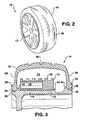
- FIG. 1 An example of a run-flat tire assembly 10 containing components that may be tested in accordance with embodiments of the present invention is shown in FIG. 1.
- the tire assembly 10 is shown as being made of three basic components. First, an alloy or steel integral wheel rim 12 is provided onto which a support member 14 is placed. The support member 14 shown in FIG. 1 is a ring. Next, a rubber tire 16 is placed onto the rim 12 and completely surrounds the support member 14. The tire assembly 10 is shown in an assembled state in FIG. 2. The tire 16 is vertically anchored to the rim 12 as described in U.S. Patent Number 5,634,993 that is assigned to the assignee of the present invention and incorporated herein by reference for all purposes in its entirety.
- the support member 14 is present in order to carry the static and dynamic loading the tire 16 is subjected to during the situation in which the tire 16 loses air pressure. Upon loss of air pressure, the tire 16 will collapse down onto the support member 14, allowing for the support member 14 to assume the loading.
- the support member 14 is shown in FIG. 1 as being an elastomeric ring; however, other types of support members 14 may be envisioned and tested in conjunction with the present invention.
- the support member 14 may be configured as that shown in U.S. Patent Number 5,891,279 that is assigned to the assignee of the present invention and incorporated herein by reference for all purposes in its entirety.
- the present invention is not limited to use with any one particular type of support member 14.
- a tire assembly 10 that uses a support member 14 may be referred to as a run-flat tire assembly 10.
- a run-flat tire assembly 10 is intended to allow a vehicle to be driven after a loss of air pressure for some distance while protecting the rim 12 or wheel from damage.
- other run-flat tire assemblies are known in the art that do not use a support member 14.
- One such run-flat tire assembly is disclosed in United States Patent Number 5,868,190 that is assigned to the assignee of the present invention and is incorporated herein by reference in its entirety for all purposes.
- FIG. 3 shows a partial cross sectional view of a tire assembly 10 in accordance with one exemplary embodiment of a run-flat tire assembly.
- the support member 14 is similar to that disclosed in the '279 patent mentioned above, and is located on a cylindrical section 18 of the rim 12.
- the support member 14 may have a contoured outside surface 20.
- a cavity 22 is located inside of the support member 14.
- the cavity 22 may extend the whole length of support member 14 or only around a portion of the circumference of support member 14.
- the cavity 22 is advantageous because it decreases the weight of the support member 14.
- a support member retaining flange 24 is present in order to help locate and secure the support member 14 on the cylindrical section 18 of rim 12.
- tire 16 is provided with tire tread 26 on its outer surface.
- Two side walls 28 extend from the tire tread 26 portion of tire 16.
- the side walls 28 are substantially vertical in orientation once seated onto the rim 12.
- a first bead 30 is present at the end of one of the side walls 28, and a second bead 32 is present at the end of the other side wall 28.
- the use of beads 28 and 30 helps to keep the tire 16 attached to the rim 12 and also helps to create an air seal to maintain air pressure in the space 34 formed between the tire 16 and rim 12.
- Rim 12 has a first bead seat 36 and a second bead seat 38 formed therein for seating the first and second beads 30 and 32 respectively.
- the first bead seat 36 is formed by a pair of humps 40 and 42.
- the second bead seat 38 is formed by a pair of humps 44 and 46.
- An air seal is formed between the first bead 30 and the first bead seat 36.
- an air seal is also formed between the second bead 32 and the second bead seat 38.
- tire 16 engages support member 14 enabling continued travel of a vehicle with reasonable and appropriate operation by the driver.
- any relative movement or shifting between support member 14 and rim 12 may cause heat build-up and wear of support member 14 due to the frictional forces present at the areas of contact.
- a loss of performance and life of support member 14 and other components may result. While such relative movement may occur whenever the tire 16 is rotating, such movement is more likely to occur under high torque conditions such as during acceleration, deceleration, or operation at high speeds. Accordingly, the ability to test for such relative movement among various designs for support member 14 and/or related components is desirable for this and other reasons.
- FIGS. 4 and 5 an exemplary embodiment of a method for centrifugally testing a run-flat tire component is illustrated.
- a support member or support ring 48 is mounted on a wheel 50.
- support ring 48 and wheel 50 are exemplary only. Each may take on any number of design configurations as are desired for testing.
- the contact surfaces between wheel 50 and support ring 48 create substantially similar or identical frictional forces as would be encountered during actual operation. More specifically, the contact surfaces mimic the frictional forces that would be encountered between the support ring 14 and rim 12 illustrated in FIG. 3.
- Wheel 50 is connected to a rotatable power source 52, which is represented schematically in FIG. 4.
- power source 52 is equipped with controls for setting and determining the rate of acceleration, deceleration, and/or speed of rotation of wheel 50 during testing.
- rotatable power source 52 is used to rotate wheel 50 and the attached support ring 48 under conditions that would be encountered during use of a run-flat tire on a vehicle.
- rotatable power source 52 is capable of accelerating and decelerating wheel 50 at rates similar to and perhaps higher than the rates a wheel might experience during operation of a vehicle.
- rotatable power source 52 can subject wheel 50 to rotation speeds at least as high as what might be obtained during operation of a vehicle.
- the position of support ring 48 relative to wheel 50 is determined prior to rotating wheel 50.
- a first mark 54 is placed on the support ring 48, and a second mark 56 is placed in an adjacent location on wheel 50.
- the position of the support ring 48 relative to wheel 50 is noted prior to rotation of wheel 50.
- wheel 50 and support ring 48 are caused to rotate until a desired or determined speed is obtained. Such rotation is illustrated by movement arrow 58 in FIG. 4. While movement arrow 58 shows counterclockwise rotation, such rotation of wheel 50 may also be clockwise if desired.
- the rotation of the wheel 50 is slowed at a constant rate or constant amount of deceleration until the wheel 50 stops rotating.
- Any desired deceleration rate may be selected.
- the deceleration rate may be based on the specifications for a vehicle braking system such as the maximum rate of deceleration provided or obtainable from a vehicle's braking system.
- a deceleration rate in the range of 20 to 50 radians per second squared is preferable.
- the present invention is not limited to any particular deceleration rate and one of skill in the art will understand that any rate of deceleration may be selected using the teachings disclosed herein.
- the amount of any rotation of the support ring 48 relative to the wheel 50 is determined.
- this step may be accomplished by comparing the relative position of first mark 54 and second mark 56.
- FIG. 5 illustrates an example where support ring 48 has rotated angularly with respect to wheel 50. As shown, first mark 54 is no longer adjacent to second mark 56. The amount of the relative movement of first mark 54 relative to second mark 56 is an indication of the amount by which support ring 48 has rotated relative to wheel 50. Once the amount of any such rotation is determined, it may be recorded. By way of example only, the length 60 along the circumference of wheel 50 may be measured to determine the amount of any rotation. By way of further example, the angle 62 between the radii 64 and 66 formed by marks 54 and 56 and the axis of rotation A may also be used to determine and record the amount of rotation.
- the initial determined speed may be selected as relatively slow with an objective of repeating the test at new speeds that are set by increasing the initial determined speed by selected increments.
- the initial test speed may be selected as 500 revolutions per minute. Successive tests may then be performed at predefined increments of between 10 to 50 revolutions per minute. More specifically, the support ring 48 may be tested at 500 revolutions per minute, 550 revolutions per minute, 600 revolutions per minute, and so on.
- the test may be repeated at increasing speeds using predefined increments and a given rate of deceleration until one or more of the following events occurs.
- the first such event is where movement of the support ring relative to the wheel is observed.
- the conditions under which such movement occurred is recorded for future reference.
- the rate of rotation of wheel 50, the rate of deceleration of wheel 50, and the amount of rotation of support ring 48 relative to wheel 50 may be recorded.
- Such a test result may indicate the maximum rate at which a vehicle could be slowed during operation before rotation of the support ring 48 begins to occur.
- the second event at which testing is stopped is when a maximum test speed is obtained before movement of the support ring 48 relative to the wheel 50 occurs.
- maximum test speed may be determined, for example, by selecting a speed that exceeds the maximum speed reasonably expected by a vehicle that will be using such support ring 48 and/or wheel 50.
- the maximum test speed used may be 350 kilometers per hour or 3000 revolutions per minute.
- various other parameters may be used for selecting a maximum test speed as will by understood by one of skill in the art using the teachings disclosed herein.
- the third event at which testing is stopped is when a mechanical failure or damage occurs to the support ring 48. Under such event, the conditions at which failure occurred are recorded for a given design of support ring 48. In this way, this exemplary embodiment of the present invention provides a way of testing the structural integrity of a given design for support ring 48.
Landscapes
- Physics & Mathematics (AREA)
- General Physics & Mathematics (AREA)
- Tires In General (AREA)
- Testing Of Balance (AREA)
Abstract
Description
Claims (20)
- A method of testing a support ring used in a wheel assembly, comprising the steps of:positioning the support ring upon a wheel rim and noting the relative position of the support ring on the wheel rim;accelerating the wheel rim and support ring to a predetermined rotational speed;from the predetermined rotational speed, stopping the wheel rim and support ring at controlled deceleration rate; anddetermining any relative rotational movement between the support ring and the wheel rim.
- A method of testing a support ring used in a wheel assembly as in claim 1, further comprising the step of inspecting the support ring for any damage or wear after said stopping.
- A method of testing a support ring used in a wheel assembly as in claim 1 or 2, further comprising the step of recording the amount of any rotation of the support ring relative to the wheel rim.
- A method of testing a support ring used in a wheel assembly as in any one of claims 1 to 3, further comprising the step of increasing said predetermined rotational speed by a selected increment and then repeating said steps of accelerating, stopping, and determining.
- A method of testing a support ring used in a wheel assembly as in any one of claims 1 to 4, wherein said controlled deceleration rate is constant.
- A method of testing a support ring used in a wheel assembly as in any one of claims 1 to 5, wherein said controlled deceleration rate is determined from the specifications for a vehicle braking system.
- A method of testing a run-flat tire component, comprising the steps of:mounting the run-flat tire component on a wheel;marking the position of said component relative to said wheel;rotating said wheel at a selected test speed;decelerating said wheel at a determined rate of deceleration; anddetermining whether said run-flat tire component has rotated relative to said wheel.
- A method of testing a run-flat tire component as in claim 7, further comprising the step of increasing said selected test speed by a selected increment and repeating said steps of rotating, decelerating, and determining
- A method of testing a run-flat tire component as in claim 8, further comprising repeating said steps of claim 8 until one or more of the following events occurs:i) a maximum said selected speed is reached,ii) a mechanical failure is observed, andiii) damage to said run-flat tire component is observed.
- A method of testing a run-flat tire component as in claim 8 or 9, wherein said selected increment is 1 to 60 revolutions per minute.
- A method of testing a run-flat tire component as in any one of claims 7 to 10, further comprising the step of recording the amount by which said component has rotated relative to said wheel.
- A method of testing a run-flat tire component as in any one of claims 7 to 11, further comprising the step of inspecting said run-flat tire component for any damage or wear.
- A method for centrifugally testing a run-flat tire component, comprising the steps of:mounting a run-flat tire component on a wheel;connecting said wheel to rotatable power source;placing a first mark on said run-flat tire component, placing a second mark on said wheel, wherein said first mark and said second mark are located adjacent to each other;rotating said wheel at a determined speed with said rotatable power source;slowing said wheel at a constant rate until said wheel stops rotating; anddetermining whether said run-flat tire component has rotated relative to said wheel.
- A method for centrifugally testing a run-flat tire component as in claim 13, further comprising the step of recording the amount of any rotation of said run-flat tire component relative to said wheel.
- A method for centrifugally testing a run-flat tire component as in claim 13 or 14, further comprising the stepss of increasing said determined speed by a selected increment and repeating said steps of rotating, slowing, and determining.
- A method for centrifugally testing a run-flat tire component as in any one of claims 13 to 15, further comprising the step of inspecting said run-flat tire component for damage after said step of slowing.
- A method for centrifugally testing a run-flat tire component as in claim 16, further comprising the steps of increasing said determined speed by a selected increment and repeating said steps of rotating, slowing, determining, and inspecting.
- A method for centrifugally testing a run-flat tire component as in claim 17, further comprising the step of repeating said rotating, slowing, determining, inspecting, and increasing steps until a maximum determined speed is obtained.
- A method for centrifugally testing a run-flat tire component as in claim 17 or 18, further comprising the step of repeating said rotating, slowing, determining, inspecting, and increasing steps until rotation of said run-flat tire component relative to said wheel is determined.
- A method for centrifugally testing a run-flat tire component as in any one of claims 17 to 19, further comprising the step of repeating said rotating, slowing, determining, inspecting, and increasing steps until damage to said run-flat tire component occurs.
Applications Claiming Priority (2)
| Application Number | Priority Date | Filing Date | Title |
|---|---|---|---|
| US141694 | 2002-05-07 | ||
| US10/141,694 US6776034B2 (en) | 2002-05-07 | 2002-05-07 | Method of testing a run-flat tire component |
Publications (2)
| Publication Number | Publication Date |
|---|---|
| EP1361422A2 true EP1361422A2 (en) | 2003-11-12 |
| EP1361422A3 EP1361422A3 (en) | 2006-02-15 |
Family
ID=29249821
Family Applications (1)
| Application Number | Title | Priority Date | Filing Date |
|---|---|---|---|
| EP03010119A Withdrawn EP1361422A3 (en) | 2002-05-07 | 2003-05-05 | A method of testing a run-flat tire component |
Country Status (9)
| Country | Link |
|---|---|
| US (1) | US6776034B2 (en) |
| EP (1) | EP1361422A3 (en) |
| JP (1) | JP2004001733A (en) |
| KR (1) | KR20030087544A (en) |
| CN (1) | CN1459386A (en) |
| AU (1) | AU2003203998A1 (en) |
| BR (1) | BR0301314A (en) |
| CA (1) | CA2428291A1 (en) |
| MX (1) | MXPA03003943A (en) |
Cited By (1)
| Publication number | Priority date | Publication date | Assignee | Title |
|---|---|---|---|---|
| FR2886401A1 (en) * | 2005-05-27 | 2006-12-01 | Michelin Soc Tech | METHOD AND DEVICE FOR MONITORING TIRE SUPPORT SUPPORT |
Families Citing this family (3)
| Publication number | Priority date | Publication date | Assignee | Title |
|---|---|---|---|---|
| FR2877088B1 (en) * | 2004-10-25 | 2007-01-12 | Michelin Soc Tech | METHOD OF DECOINING A PNEUMATIC |
| WO2019163016A1 (en) * | 2018-02-21 | 2019-08-29 | 三菱重工機械システム株式会社 | Rim replacement device, tire test device, and rim replacement method |
| CN113218678B (en) * | 2021-04-29 | 2022-12-06 | 山东省三利轮胎制造有限公司 | Intelligent detection system and detection method for manufacturing of run-flat tire |
Family Cites Families (8)
| Publication number | Priority date | Publication date | Assignee | Title |
|---|---|---|---|---|
| US3049162A (en) * | 1956-03-27 | 1962-08-14 | Alweg Forschung Gmbh | Emergency support |
| BE556144A (en) * | 1956-03-27 | |||
| US3976114A (en) * | 1975-05-22 | 1976-08-24 | Patecell Theodore C | Sectional run-flat tire insert with coupling means, permitting automatic installation |
| US4573509A (en) * | 1983-06-24 | 1986-03-04 | The Goodyear Tire & Rubber Company | Run flat device |
| GB8926878D0 (en) * | 1989-11-28 | 1990-01-17 | Houghton Adrian K | Run flat tyres,inserts and wheels |
| FR2699121B1 (en) | 1992-12-11 | 1995-03-17 | Michelin & Cie | Set formed by a tire, a rim and a support ring. |
| FR2746347A1 (en) | 1996-03-19 | 1997-09-26 | Michelin & Cie | SAFETY SUPPORT IN FLEXIBLE ELASTOMERIC MATERIAL FOR TIRES |
| US5868190A (en) | 1997-06-10 | 1999-02-09 | Michelin Recherche Et Technique, S.A. | Run-flat tire with an improved bead to rim interface |
-
2002
- 2002-05-07 US US10/141,694 patent/US6776034B2/en not_active Expired - Fee Related
-
2003
- 2003-05-02 MX MXPA03003943A patent/MXPA03003943A/en unknown
- 2003-05-05 EP EP03010119A patent/EP1361422A3/en not_active Withdrawn
- 2003-05-06 BR BR0301314-6A patent/BR0301314A/en not_active IP Right Cessation
- 2003-05-06 AU AU2003203998A patent/AU2003203998A1/en not_active Abandoned
- 2003-05-06 CA CA002428291A patent/CA2428291A1/en not_active Abandoned
- 2003-05-06 JP JP2003127947A patent/JP2004001733A/en not_active Abandoned
- 2003-05-06 KR KR10-2003-0028507A patent/KR20030087544A/en not_active Withdrawn
- 2003-05-07 CN CN03138443A patent/CN1459386A/en active Pending
Cited By (1)
| Publication number | Priority date | Publication date | Assignee | Title |
|---|---|---|---|---|
| FR2886401A1 (en) * | 2005-05-27 | 2006-12-01 | Michelin Soc Tech | METHOD AND DEVICE FOR MONITORING TIRE SUPPORT SUPPORT |
Also Published As
| Publication number | Publication date |
|---|---|
| US6776034B2 (en) | 2004-08-17 |
| BR0301314A (en) | 2004-08-17 |
| CA2428291A1 (en) | 2003-11-07 |
| JP2004001733A (en) | 2004-01-08 |
| AU2003203998A1 (en) | 2003-11-27 |
| MXPA03003943A (en) | 2004-10-15 |
| KR20030087544A (en) | 2003-11-14 |
| EP1361422A3 (en) | 2006-02-15 |
| CN1459386A (en) | 2003-12-03 |
| US20030209095A1 (en) | 2003-11-13 |
Similar Documents
| Publication | Publication Date | Title |
|---|---|---|
| US4351382A (en) | Tire and wheel rim assemblies | |
| JP4694792B2 (en) | Apparatus and method for measuring tire balance with force variation measuring machine | |
| US4148348A (en) | Tire and wheel rim assemblies | |
| CA1094436A (en) | Tyre and wheel rim assemblies | |
| EP0754572B1 (en) | A pneumatic tyre | |
| US4015652A (en) | Tire and rim assembly | |
| JP2018512333A (en) | Tire with electronic device | |
| US5690762A (en) | Emergency ring for a vehicle wheel | |
| JP2004524216A (en) | Safety support for vehicle tires | |
| US20030098109A1 (en) | Tire to rim rotation limiter for a run-flat assembly | |
| US6776034B2 (en) | Method of testing a run-flat tire component | |
| RU2234424C2 (en) | Method of mounting pneumatic tire on wheel hub | |
| JPH07164835A (en) | Radial ply pneumatic tire | |
| EP0358490B1 (en) | Tyre and rim assembly and tyre for use thereon | |
| US4274466A (en) | Tire and wheel rim assemblies | |
| US6994133B2 (en) | Low or no pressure usage indicator for a tire | |
| US5311916A (en) | Wheel rim well safety device | |
| GB2064446A (en) | Tyre and wheel rim assemblies | |
| WO2000030871A1 (en) | Optimized ramp angle on wheel to reduce outboard bead mounting pressure | |
| JPS5920483B2 (en) | air tire wheels | |
| RU2808032C1 (en) | Tubeless high safety wheel | |
| US3134420A (en) | Inner tube and rubber valve | |
| JP2005007928A (en) | Support ring, tire assembly and vehicle using the support ring | |
| US6820015B2 (en) | Method and installation for predicting the maximum running distance, in degraded mode, of a mounted assembly | |
| JPS5930564B2 (en) | Safety structure for pneumatic tire wheels |
Legal Events
| Date | Code | Title | Description |
|---|---|---|---|
| PUAI | Public reference made under article 153(3) epc to a published international application that has entered the european phase |
Free format text: ORIGINAL CODE: 0009012 |
|
| AK | Designated contracting states |
Kind code of ref document: A2 Designated state(s): AT BE BG CH CY CZ DE DK EE ES FI FR GB GR HU IE IT LI LU MC NL PT RO SE SI SK TR |
|
| AX | Request for extension of the european patent |
Extension state: AL LT LV MK |
|
| PUAL | Search report despatched |
Free format text: ORIGINAL CODE: 0009013 |
|
| AK | Designated contracting states |
Kind code of ref document: A3 Designated state(s): AT BE BG CH CY CZ DE DK EE ES FI FR GB GR HU IE IT LI LU MC NL PT RO SE SI SK TR |
|
| AX | Request for extension of the european patent |
Extension state: AL LT LV MK |
|
| RIC1 | Information provided on ipc code assigned before grant |
Ipc: G01M 19/00 20060101ALI20051223BHEP Ipc: G01M 17/013 20060101AFI20051223BHEP |
|
| 17P | Request for examination filed |
Effective date: 20060816 |
|
| 17Q | First examination report despatched |
Effective date: 20060914 |
|
| AKX | Designation fees paid |
Designated state(s): AT BE BG CH CY CZ DE DK EE ES FI FR GB GR HU IE IT LI LU MC NL PT RO SE SI SK TR |
|
| STAA | Information on the status of an ep patent application or granted ep patent |
Free format text: STATUS: THE APPLICATION IS DEEMED TO BE WITHDRAWN |
|
| 18D | Application deemed to be withdrawn |
Effective date: 20070125 |