EP1361352A1 - Driver of direct acting valve for internal combustion engine - Google Patents
Driver of direct acting valve for internal combustion engine Download PDFInfo
- Publication number
- EP1361352A1 EP1361352A1 EP02711446A EP02711446A EP1361352A1 EP 1361352 A1 EP1361352 A1 EP 1361352A1 EP 02711446 A EP02711446 A EP 02711446A EP 02711446 A EP02711446 A EP 02711446A EP 1361352 A1 EP1361352 A1 EP 1361352A1
- Authority
- EP
- European Patent Office
- Prior art keywords
- internal combustion
- combustion engine
- valve
- electromagnetic actuator
- direct
- Prior art date
- Legal status (The legal status is an assumption and is not a legal conclusion. Google has not performed a legal analysis and makes no representation as to the accuracy of the status listed.)
- Withdrawn
Links
Images


Classifications
-
- F—MECHANICAL ENGINEERING; LIGHTING; HEATING; WEAPONS; BLASTING
- F02—COMBUSTION ENGINES; HOT-GAS OR COMBUSTION-PRODUCT ENGINE PLANTS
- F02D—CONTROLLING COMBUSTION ENGINES
- F02D13/00—Controlling the engine output power by varying inlet or exhaust valve operating characteristics, e.g. timing
- F02D13/02—Controlling the engine output power by varying inlet or exhaust valve operating characteristics, e.g. timing during engine operation
- F02D13/0253—Fully variable control of valve lift and timing using camless actuation systems such as hydraulic, pneumatic or electromagnetic actuators, e.g. solenoid valves
-
- F—MECHANICAL ENGINEERING; LIGHTING; HEATING; WEAPONS; BLASTING
- F01—MACHINES OR ENGINES IN GENERAL; ENGINE PLANTS IN GENERAL; STEAM ENGINES
- F01L—CYCLICALLY OPERATING VALVES FOR MACHINES OR ENGINES
- F01L9/00—Valve-gear or valve arrangements actuated non-mechanically
- F01L9/20—Valve-gear or valve arrangements actuated non-mechanically by electric means
-
- F—MECHANICAL ENGINEERING; LIGHTING; HEATING; WEAPONS; BLASTING
- F01—MACHINES OR ENGINES IN GENERAL; ENGINE PLANTS IN GENERAL; STEAM ENGINES
- F01L—CYCLICALLY OPERATING VALVES FOR MACHINES OR ENGINES
- F01L1/00—Valve-gear or valve arrangements, e.g. lift-valve gear
- F01L1/02—Valve drive
- F01L1/04—Valve drive by means of cams, camshafts, cam discs, eccentrics or the like
- F01L1/047—Camshafts
- F01L1/053—Camshafts overhead type
- F01L2001/0535—Single overhead camshafts [SOHC]
-
- F—MECHANICAL ENGINEERING; LIGHTING; HEATING; WEAPONS; BLASTING
- F01—MACHINES OR ENGINES IN GENERAL; ENGINE PLANTS IN GENERAL; STEAM ENGINES
- F01L—CYCLICALLY OPERATING VALVES FOR MACHINES OR ENGINES
- F01L9/00—Valve-gear or valve arrangements actuated non-mechanically
- F01L9/20—Valve-gear or valve arrangements actuated non-mechanically by electric means
- F01L9/21—Valve-gear or valve arrangements actuated non-mechanically by electric means actuated by solenoids
- F01L2009/2105—Valve-gear or valve arrangements actuated non-mechanically by electric means actuated by solenoids comprising two or more coils
-
- F—MECHANICAL ENGINEERING; LIGHTING; HEATING; WEAPONS; BLASTING
- F01—MACHINES OR ENGINES IN GENERAL; ENGINE PLANTS IN GENERAL; STEAM ENGINES
- F01L—CYCLICALLY OPERATING VALVES FOR MACHINES OR ENGINES
- F01L9/00—Valve-gear or valve arrangements actuated non-mechanically
- F01L9/20—Valve-gear or valve arrangements actuated non-mechanically by electric means
- F01L9/21—Valve-gear or valve arrangements actuated non-mechanically by electric means actuated by solenoids
- F01L2009/2146—Latching means
- F01L2009/2148—Latching means using permanent magnet
-
- F—MECHANICAL ENGINEERING; LIGHTING; HEATING; WEAPONS; BLASTING
- F01—MACHINES OR ENGINES IN GENERAL; ENGINE PLANTS IN GENERAL; STEAM ENGINES
- F01L—CYCLICALLY OPERATING VALVES FOR MACHINES OR ENGINES
- F01L2800/00—Methods of operation using a variable valve timing mechanism
-
- F—MECHANICAL ENGINEERING; LIGHTING; HEATING; WEAPONS; BLASTING
- F02—COMBUSTION ENGINES; HOT-GAS OR COMBUSTION-PRODUCT ENGINE PLANTS
- F02B—INTERNAL-COMBUSTION PISTON ENGINES; COMBUSTION ENGINES IN GENERAL
- F02B2275/00—Other engines, components or details, not provided for in other groups of this subclass
- F02B2275/20—SOHC [Single overhead camshaft]
-
- F—MECHANICAL ENGINEERING; LIGHTING; HEATING; WEAPONS; BLASTING
- F02—COMBUSTION ENGINES; HOT-GAS OR COMBUSTION-PRODUCT ENGINE PLANTS
- F02D—CONTROLLING COMBUSTION ENGINES
- F02D41/00—Electrical control of supply of combustible mixture or its constituents
- F02D41/0002—Controlling intake air
- F02D2041/001—Controlling intake air for engines with variable valve actuation
-
- F—MECHANICAL ENGINEERING; LIGHTING; HEATING; WEAPONS; BLASTING
- F02—COMBUSTION ENGINES; HOT-GAS OR COMBUSTION-PRODUCT ENGINE PLANTS
- F02D—CONTROLLING COMBUSTION ENGINES
- F02D41/00—Electrical control of supply of combustible mixture or its constituents
- F02D41/20—Output circuits, e.g. for controlling currents in command coils
-
- Y—GENERAL TAGGING OF NEW TECHNOLOGICAL DEVELOPMENTS; GENERAL TAGGING OF CROSS-SECTIONAL TECHNOLOGIES SPANNING OVER SEVERAL SECTIONS OF THE IPC; TECHNICAL SUBJECTS COVERED BY FORMER USPC CROSS-REFERENCE ART COLLECTIONS [XRACs] AND DIGESTS
- Y02—TECHNOLOGIES OR APPLICATIONS FOR MITIGATION OR ADAPTATION AGAINST CLIMATE CHANGE
- Y02T—CLIMATE CHANGE MITIGATION TECHNOLOGIES RELATED TO TRANSPORTATION
- Y02T10/00—Road transport of goods or passengers
- Y02T10/10—Internal combustion engine [ICE] based vehicles
- Y02T10/12—Improving ICE efficiencies
Definitions
- the present invention relates to a drive unit for a direct-acting valve for internal combustion engines, and more specifically, relates to a drive unit for a direct-acting valve for internal combustion engines that can reduce noise at the time of operation of the internal combustion engine.
- valve apparatus for the internal combustion engine there is known one in which an inlet valve and an exhaust valve are directly driven to open or close by an electromagnetic actuator.
- the valve driven in this manner is referred to as a direct-acting valve.
- the drive unit for this direct-acting valve applies, for example, a positive current to the electromagnetic actuator, to move the valve in the opening direction by a specific distance, and applies a negative current to the electromagnetic actuator, to move the valve in the closing direction.
- the present invention has been achieved in order to solve the above problems. It is an object of the present invention to provide a drive unit for a direct-acting valve for internal combustion engines that can obtain a quiet internal combustion engine, with noise suppressed.
- a drive unit for a direct-acting valve for an internal combustion engine comprises an inlet valve slidably arranged near an inlet port of the internal combustion engine for opening or closing the inlet port, an electromagnetic actuator that drives the inlet valve to open or close, and a current control unit that controls a driving current supplied to the electromagnetic actuator, wherein the current control unit continuously supplies the driving current having a specific value to the electromagnetic actuator, based on the operation condition of the internal, combustion engine.
- the drive unit for the direct-acting valve for the internal combustion engine according to claim 2 of the present invention is such that the current control unit according to claim 1 continuously supplies the driving current having a specific value to the electromagnetic actuator, based on a target output of the internal combustion engine.
- the drive unit for the direct-acting valve for the internal combustion engine according to claim 3 of the present invention is such that the target output according to claim 2 is detected by a control input of an accelerator provided to the internal combustion engine.
- the drive unit for the direct-acting valve for the internal combustion engine according to claim 4 of the present invention is such that when the internal combustion engine is in the idling state, the current control unit according to claim 1 continuously supplies the driving current having the specific value to the electromagnetic actuator.
- the drive unit for the direct-acting valve for the internal combustion engine according to claim 5 of the present invention is such that the idling state of the internal combustion engine according to claim 4 is detected by a control input of an accelerator provided to the internal combustion engine.
- the drive unit for the direct-acting valve for the internal combustion engine according to claim 6 of the present invention is such that the idling state of the internal combustion engine according to claim 4 is detected by the revolution speed of the internal combustion engine.
- the drive unit for the direct-acting valve for the internal combustion engine according to claim 7 of the present invention is such that the electromagnetic actuator according to any one of claim 1 to 6 comprises a linear motor.
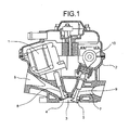
- Fig. 1 shows a cylinder head in an internal combustion engine, in which an electromagnetic actuator 1 constituting the drive unit for the direct-acting valve for internal combustion engines of the embodiment (hereinafter “drive unit”) is assembled.
- drive unit constituting the drive unit for the direct-acting valve for internal combustion engines of the embodiment
- a cylinder head 2 shown in Fig. 1 comprises an inlet port 4 that opens toward a combustion chamber 3 for feeding air-fuel mixture to the combustion chamber 3, an exhaust port 5 that opens toward the combustion chamber 3 for exhausting combustion gas, an inlet path 6 communicated with the inlet port 4, and an exhaust path 7 communicated with the exhaust port 5.
- An inlet valve 8 for opening or closing the inlet port 4 and an exhaust valve 9 for opening or closing the exhaust port 5 are provided slidably in the cylinder head 2, and the electromagnetic actuator 1 connected to the inlet valve 8 is fitted thereto.
- a cam 10 that drives the exhaust valve 9 to open or close by rotating synchronously with the rotation of a crankshaft (not shown) in the internal combustion engine is provided axially above the exhaust valve 9.
- the electromagnetic actuator 1 a linear motor is used in this embodiment, and the inlet port 4 is opened or closed by shifting the inlet valve 8 in the axial direction thereof.
- the electromagnetic actuator 1 holds a valve seat for the inlet valve 8 to a position abutting against the inlet port 4 with a specific pressure, as shown in Fig. 2, at a center valve position in the non-energized condition, and shifts the inlet valve 8, as shown in Figs. 3(a) and 3(b), to a valve opening position or a valve closing position, when a reciprocal current is applied.
- the motion stroke, the valve opening time, and the valve closing time of the inlet valve 8 are set depending on the size and the application time of the current applied to the electromagnetic actuator 1.
- the drive unit comprises, as shown in Fig. 4, a current control unit 11 that controls the driving current V supplied to the electromagnetic actuator 1.
- This current control unit 11 is for continuously supplying the driving current having a specific value to the electromagnetic actuator 1, based on the operation condition of the internal combustion engine.
- the current control unit 11 comprises an FV converter 14 that converts the revolution speed of the internal combustion engine 12 to a voltage V1, based on a pulse signal relating to a crank angle output from a crank angle sensor 13 provided in the internal combustion engine 12, amplifiers 15 and 16 that output a signal obtained by adjusting the level of the voltage V1 as a real revolution speed current signal i1, a load setting circuit 17 that sets a target output based on the accelerator opening and outputs the revolution speed of the internal combustion engine 12 corresponding to this target output as a voltage, and an idling setting circuit 18 that outputs the revolution speed of the internal combustion engine 12 at the time of idling as a voltage.
- FV converter 14 that converts the revolution speed of the internal combustion engine 12 to a voltage V1, based on a pulse signal relating to a crank angle output from a crank angle sensor 13 provided in the internal combustion engine 12
- amplifiers 15 and 16 that output a signal obtained by adjusting the level of the voltage V1 as a real revolution speed current signal i1
- the current control unit 11 also includes a target revolution speed setting circuit 19 that outputs a voltage V2 output from these, an amplifier 20 that outputs the voltage V2 from the target revolution speed setting circuit 19 as a target revolution speed current signal i2, an adder 21 that calculates a deviation between the real revolution speed current signal i1 and the target revolution speed current signal i2, an amplifier 22 that adjusts a deviation current signal i3 determined by the adder 21 to output it as a target current signal i4, an ampere meter 23 that detects a current i applied to the electromagnetic actuator 1, an adder 24 that calculates a deviation between the driving current i detected by the driving ampere meter 23 and the target current signal i4, an amplifier 25 that adjusts a deviation current i5 output from the adder 24, and an output amplifier 26 that applies the driving current V to the electromagnetic actuator 1, based on an adjusted deviation voltage V3 output from the amplifier 25.
- a target revolution speed setting circuit 19 that outputs a voltage V2 output from these
- an amplifier 20 that outputs the voltage
- reference sign F denotes a crank angle signal output from the crank angle sensor 13, which is output continuously when the internal combustion engine 12 is in the operation condition.
- a line E denotes a pulse signal at a fuel injection timing output to the fuel injection system
- a line G denotes a pulse signal at the time of ignition
- line C denotes a stroke of the inlet valve 8
- a line D denotes a flow velocity of a gas in the inlet path 6.
- the voltage signal V1 as the information of the real revolution speed of the internal combustion engine 12 is output from the FV converter 14, and the voltage signal V2 as the information of the target revolution speed is output from the target revolution speed setting circuit 19.
- the target current signal i4 is calculated from the voltage signal V1 and the voltage signal V2, the current i supplied to the electromagnetic actuator 1 is detected, and the drive voltage V is generated by the target current signal i4 and the current i, and applied to the electromagnetic actuator 1.
- the driving current having a specific value is applied to the electromagnetic actuator 1, and the inlet valve 8 is pressed against the inlet port 4, by an attraction when the electromagnetic actuator 1 is not charged with electricity and an attraction by the driving current.
- valve closing force the sum total of the both attraction.
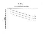
- the attraction that is, a load as a returning force acting in a direction of closing the inlet valve 8 is, as shown in Fig. 7, determined by the size of the driving current applied to the electromagnetic actuator 1 and a lift (valve opening) of the inlet valve 8.
- the lift of the inlet valve 8 is controlled by controlling the driving current to be applied to the electromagnetic actuator 1.
- the quantity of air intake flowing into the combustion chamber via the inlet port 4 can be controlled by controlling the driving current applied to the electromagnetic actuator 1, and it is possible to control the output of the internal combustion engine 12, by allowing the inlet port 8 itself to function as a throttle valve.
- This intake state is shown by the flow velocity in the inlet path 6, expressed by the line D in Fig. 5.
- the gas flows into the combustion chamber 3, to increase the pressure in the combustion chamber 3, and when air intake is completed, the inlet valve 8 is shifted in the valve closing direction by the valve closing force by the electromagnetic actuator 1, and the valve seat is seated on the inlet port 4, thereby the inlet port 4 is closed to complete the intake stroke.
- the stroke of the inlet valve 8 in the intake stroke is determined by the negative pressure in the combustion chamber 3, and hence the stroke is suppressed to a minimum.
- the shift quantity of the inlet valve 8 in the valve closing direction becomes small, and the impact force at the time of seating the valve seat on the inlet port 4 can be suppressed, and as a result, occurrence of noise can be suppressed.
- the voltage signal V2 as the information of the target revolution speed is set in the load setting circuit 17.
- the voltage signal V2 at the time of normal operation is set smaller, as the target revolution speed increases, thereby the attraction of the inlet valve 8 by the driving current decreases, and the valve closing force decreases.
- the revolution speed of the internal combustion engine 12 is kept at the target revolution speed.
- the load setting circuit 17 is mechanically or electrically connected to the accelerator operated by a driver, so that it can be adjusted by the operation of the accelerator.
- the idling setting circuit 18 is connected to the accelerator mechanically or electrically, and outputs the voltage signal V2 at the time of idling, when the accelerator is in the non-operated state.
- the electromagnetic actuator 1 allows a constant valve closing force resisting the inlet pressure of the internal combustion engine 12 to act on the inlet valve 8, thereby the inlet valve 8 is opened by a difference between the valve closing force and the valve opening force by the negative pressure generated in the combustion chamber 3.
- the voltage signal V2 corresponding to the target revolution speed is set within the range of from the maximum value to zero.
- the intake quantity corresponding to the operation condition (load condition) required for the internal combustion engine 12 can be supplied, without monitoring the lift and the valve opening period of the inlet valve 8.
- the lift of the inlet valve 8 is automatically adjusted corresponding to the operation condition, to be the minimum lift corresponding to the operation condition, and hence the impact at the time of seating the valve seat on the inlet valve 8 can be made as small as possible, thereby suppressing the occurrence of noise.
- the inlet valve 8 is forcibly opened, to ensure the lift sufficiently, thereby it becomes possible to supply the intake amount sufficiently.
- the drive unit for the direct-acting valve for internal combustion engines comprises the electromagnetic actuator that drives the inlet valve to open or close, and a current control unit that controls the driving current to be supplied to the electromagnetic actuator.
- the current control unit continuously supplies the driving current having a specific value to the electromagnetic actuator, based on the operation condition of the internal combustion engine. Therefore, the inlet valve lift is automatically set by a balance between the valve opening force by the negative pressure acting on the combustion chamber of the internal combustion engine and the valve closing force, thereby suppressing the inlet valve lift to a minimum, to alleviate the impact force at the time of closing the valve. As a result, the occurrence of noise can be suppressed.
- the impact noise at the time of seating the valve seat on the inlet valve is suppressed, to thereby suppress the noise of the internal combustion engine at the time of idling.
- quiet internal combustion engine can be obtained.
Landscapes
- Engineering & Computer Science (AREA)
- Mechanical Engineering (AREA)
- General Engineering & Computer Science (AREA)
- Combustion & Propulsion (AREA)
- Electromagnetism (AREA)
- Chemical & Material Sciences (AREA)
- Physics & Mathematics (AREA)
- Output Control And Ontrol Of Special Type Engine (AREA)
- Electrical Control Of Air Or Fuel Supplied To Internal-Combustion Engine (AREA)
- Valve Device For Special Equipments (AREA)
- Characterised By The Charging Evacuation (AREA)
- Combined Controls Of Internal Combustion Engines (AREA)
- Reciprocating, Oscillating Or Vibrating Motors (AREA)
Abstract
Description
Claims (7)
- A drive unit for a direct-acting valve for an internal combustion engine, comprising:wherein said current control unit continuously supplies the driving current having a specific value to the electromagnetic actuator, based on an operating condition of the internal combustion engine.an inlet valve slidably arranged near an inlet port of the internal combustion engine for opening and closing the inlet port;an electromagnetic actuator that drives said inlet valve in a manner to open and close the inlet valve; anda current control unit that controls a driving current supplied to said electromagnetic actuator,
- The drive unit for the direct-acting valve for the internal combustion engine according to claim 1, wherein the current control unit continuously supplies the driving current having a specific value to said electromagnetic actuator, based on a target output of the internal combustion engine.
- The drive unit for the direct-acting valve for the internal combustion engine according to claim 2, wherein said target output is detected by a control input of an accelerator provided to the internal combustion engine.
- The drive unit for the direct-acting valve for the internal combustion engine according to claim 1, wherein when the internal combustion engine is in the idling state, said current control unit continuously supplies the driving current having the specific value to the electromagnetic actuator.
- The drive unit for the direct-acting valve for the internal combustion engine according to claim 4, wherein said idling state of the internal combustion engine is detected by a control input of an accelerator provided to the internal combustion engine.
- The drive unit for the direct-acting valve for the internal combustion engine according to claim 4, wherein said idling state of the internal combustion engine is detected based on revolution speed of the internal combustion engine.
- The drive unit for the direct-acting valve for the internal combustion engine according to any one of claims 1 to 6, wherein said electromagnetic actuator comprises a linear motor.
Applications Claiming Priority (3)
| Application Number | Priority Date | Filing Date | Title |
|---|---|---|---|
| JP2001036795 | 2001-02-14 | ||
| JP2001036795A JP2002242708A (en) | 2001-02-14 | 2001-02-14 | Drive device for direct acting valve for internal combustion engine |
| PCT/JP2002/001125 WO2002064960A1 (en) | 2001-02-14 | 2002-02-12 | Driver of direct acting valve for internal combustion engine |
Publications (2)
| Publication Number | Publication Date |
|---|---|
| EP1361352A1 true EP1361352A1 (en) | 2003-11-12 |
| EP1361352A4 EP1361352A4 (en) | 2005-01-26 |
Family
ID=18900021
Family Applications (1)
| Application Number | Title | Priority Date | Filing Date |
|---|---|---|---|
| EP02711446A Withdrawn EP1361352A4 (en) | 2001-02-14 | 2002-02-12 | DIRECT ACTING VALVE DRIVER FOR INTERNAL COMBUSTION ENGINE |
Country Status (4)
| Country | Link |
|---|---|
| US (1) | US6920848B2 (en) |
| EP (1) | EP1361352A4 (en) |
| JP (1) | JP2002242708A (en) |
| WO (1) | WO2002064960A1 (en) |
Families Citing this family (3)
| Publication number | Priority date | Publication date | Assignee | Title |
|---|---|---|---|---|
| JP2002242708A (en) * | 2001-02-14 | 2002-08-28 | Mikuni Corp | Drive device for direct acting valve for internal combustion engine |
| JP2003217925A (en) | 2002-01-21 | 2003-07-31 | Mikuni Corp | Linear actuator device and drive control method |
| KR101122087B1 (en) | 2006-07-20 | 2012-03-15 | 엘지전자 주식회사 | Mobile Communication Terminal And Method Of Changing Function Mode Using The Same |
Family Cites Families (25)
| Publication number | Priority date | Publication date | Assignee | Title |
|---|---|---|---|---|
| JPH02123212A (en) | 1988-10-31 | 1990-05-10 | Isuzu Motors Ltd | valve control device |
| JP2610187B2 (en) | 1989-04-28 | 1997-05-14 | 株式会社いすゞセラミックス研究所 | Valve drive |
| DE19531435B4 (en) * | 1995-08-26 | 2006-11-16 | Fev Motorentechnik Gmbh | Method for adapting the control of an electromagnetic actuator to operational changes |
| GB2319296A (en) * | 1996-11-13 | 1998-05-20 | Bernard Owen | I.c. engine with valves actuated electrically, eg electromagnetically |
| DE19733137A1 (en) * | 1997-07-31 | 1999-02-04 | Fev Motorentech Gmbh & Co Kg | Excitation control method for valve on piston engine |
| JP3695118B2 (en) * | 1998-01-12 | 2005-09-14 | トヨタ自動車株式会社 | Control device for electromagnetically driven valve |
| JP3465568B2 (en) * | 1998-01-19 | 2003-11-10 | トヨタ自動車株式会社 | Electromagnetic drive valve control device for internal combustion engine |
| US6604497B2 (en) * | 1998-06-05 | 2003-08-12 | Buehrle, Ii Harry W. | Internal combustion engine valve operating mechanism |
| JP4073584B2 (en) | 1998-11-04 | 2008-04-09 | 株式会社ミクニ | Valve drive device |
| JP2002529842A (en) * | 1998-11-06 | 2002-09-10 | シーメンス オートモーティヴ コーポレイション | Compensation method for flow control of electromechanical actuators |
| JP3724542B2 (en) * | 1998-11-18 | 2005-12-07 | 日産自動車株式会社 | Intake air amount control device for variable valve engine |
| JP2000154740A (en) * | 1998-11-19 | 2000-06-06 | Nissan Motor Co Ltd | Control device for variable valve engine |
| JP3932712B2 (en) * | 1999-01-12 | 2007-06-20 | 日産自動車株式会社 | Engine intake control device |
| EP1063393B1 (en) * | 1999-06-23 | 2006-04-12 | Nissan Motor Co., Ltd. | Intake-air quantity control apparatus for internal combustion engine with variable valve timing system |
| JP3582409B2 (en) * | 1999-06-30 | 2004-10-27 | 日産自動車株式会社 | Control method of internal combustion engine |
| JP3800896B2 (en) * | 1999-12-03 | 2006-07-26 | 日産自動車株式会社 | Control device for electromagnetic actuator |
| JP3807174B2 (en) * | 1999-12-06 | 2006-08-09 | 日産自動車株式会社 | Engine control device |
| JP2001234743A (en) | 2000-02-24 | 2001-08-31 | Mikuni Corp | Emission control device for internal combustion engine |
| JP4281257B2 (en) * | 2000-06-29 | 2009-06-17 | トヨタ自動車株式会社 | Engine valve drive control device |
| JP2002106373A (en) * | 2000-10-02 | 2002-04-10 | Mikuni Corp | Engine intake valve opening / closing control device using electromagnetic actuator |
| JP4281246B2 (en) * | 2000-12-21 | 2009-06-17 | トヨタ自動車株式会社 | Engine valve drive control device |
| JP2002242708A (en) * | 2001-02-14 | 2002-08-28 | Mikuni Corp | Drive device for direct acting valve for internal combustion engine |
| US6755166B2 (en) * | 2001-09-17 | 2004-06-29 | Massachusetts Institute Of Technology | Electromechanical valve drive incorporating a nonlinear mechanical transformer |
| DE10148403A1 (en) * | 2001-09-29 | 2003-04-17 | Fev Motorentech Gmbh | Method for precise control of actuator for gas change valve of IC engine, comprises two electromagnets guiding armature coupled to the valve, flux direction in coils is changed based on loading |
| US6729278B2 (en) * | 2002-09-27 | 2004-05-04 | Ford Global Technologies, Llc | Dual coil, dual lift electromechanical valve actuator |
-
2001
- 2001-02-14 JP JP2001036795A patent/JP2002242708A/en active Pending
-
2002
- 2002-02-12 US US10/467,503 patent/US6920848B2/en not_active Expired - Fee Related
- 2002-02-12 EP EP02711446A patent/EP1361352A4/en not_active Withdrawn
- 2002-02-12 WO PCT/JP2002/001125 patent/WO2002064960A1/en not_active Ceased
Also Published As
| Publication number | Publication date |
|---|---|
| US20040079330A1 (en) | 2004-04-29 |
| EP1361352A4 (en) | 2005-01-26 |
| US6920848B2 (en) | 2005-07-26 |
| WO2002064960A1 (en) | 2002-08-22 |
| JP2002242708A (en) | 2002-08-28 |
Similar Documents
| Publication | Publication Date | Title |
|---|---|---|
| EP1106792B1 (en) | Control apparatus for internal combustion engines | |
| KR100404291B1 (en) | Intake-air quantity control apparatus for internal combustion engines | |
| JP3724542B2 (en) | Intake air amount control device for variable valve engine | |
| EP0867602B1 (en) | Electromagnetically operated valve control system and the method thereof | |
| JP3831778B2 (en) | Multi-degree-of-freedom valve control system | |
| JPH09264150A (en) | Electronic turbo charger west gate valve control device | |
| JPH0223238A (en) | Power generator | |
| US7562527B2 (en) | Internal combustion engine with a supercharger | |
| EP0964141A3 (en) | Exhaust gas recirculation control apparatus for internal combustion engine | |
| EP2249473B1 (en) | Control device and control method for control valve | |
| US6920848B2 (en) | Driver or direct acting valve for internal combustion engine | |
| US6155240A (en) | Actuator control apparatus for internal combustion engine | |
| EP1798394B1 (en) | Internal combustion engine with supercharger | |
| US7086374B2 (en) | PWM control of a lifter oil manifold assembly solenoid | |
| EP1439289A4 (en) | METHOD FOR CONTROLLING EXCITATION WITH VARIABLE RETROACTION GAIN OF SOLENOID VALVE | |
| JPH11270416A (en) | Exhaust gas recirculation control valve | |
| US20040187814A1 (en) | Electromagnetically driven valve control system and method | |
| JP2001152937A (en) | Idle speed control device for internal combustion engine | |
| US4736720A (en) | Idling speed control system for internal combustion engines | |
| JP2001221071A (en) | Control device for variable valve engine | |
| JP2005147063A (en) | Drive device and drive method for direct acting valve for internal combustion engine | |
| JPH062619A (en) | Gas fuel supply system of engine | |
| JPH11200958A (en) | EGR valve | |
| JPS6210443A (en) | Internal combustion engine idle speed control device | |
| JPH1047529A (en) | Negative pressure control valve |
Legal Events
| Date | Code | Title | Description |
|---|---|---|---|
| PUAI | Public reference made under article 153(3) epc to a published international application that has entered the european phase |
Free format text: ORIGINAL CODE: 0009012 |
|
| 17P | Request for examination filed |
Effective date: 20030805 |
|
| AK | Designated contracting states |
Kind code of ref document: A1 Designated state(s): DE FR GB IT |
|
| A4 | Supplementary search report drawn up and despatched |
Effective date: 20041210 |
|
| RIC1 | Information provided on ipc code assigned before grant |
Ipc: 7F 02D 13/02 A Ipc: 7F 02D 41/00 B Ipc: 7F 01L 9/04 B |
|
| 17Q | First examination report despatched |
Effective date: 20050210 |
|
| STAA | Information on the status of an ep patent application or granted ep patent |
Free format text: STATUS: THE APPLICATION IS DEEMED TO BE WITHDRAWN |
|
| 18D | Application deemed to be withdrawn |
Effective date: 20081010 |