EP1361339A1 - Method for producing a bladed rotor for a gas turbine engine having an aluminium bronze protective coating - Google Patents
Method for producing a bladed rotor for a gas turbine engine having an aluminium bronze protective coating Download PDFInfo
- Publication number
- EP1361339A1 EP1361339A1 EP03252808A EP03252808A EP1361339A1 EP 1361339 A1 EP1361339 A1 EP 1361339A1 EP 03252808 A EP03252808 A EP 03252808A EP 03252808 A EP03252808 A EP 03252808A EP 1361339 A1 EP1361339 A1 EP 1361339A1
- Authority
- EP
- European Patent Office
- Prior art keywords
- percent
- furnishing
- hub
- rotor
- protective coating
- Prior art date
- Legal status (The legal status is an assumption and is not a legal conclusion. Google has not performed a legal analysis and makes no representation as to the accuracy of the status listed.)
- Withdrawn
Links
- 239000011253 protective coating Substances 0.000 title claims abstract description 58
- XAGFODPZIPBFFR-UHFFFAOYSA-N aluminium Chemical compound [Al] XAGFODPZIPBFFR-UHFFFAOYSA-N 0.000 title claims abstract description 17
- 238000004519 manufacturing process Methods 0.000 title 1
- 238000000034 method Methods 0.000 claims abstract description 57
- 239000007921 spray Substances 0.000 claims abstract description 32
- XEEYBQQBJWHFJM-UHFFFAOYSA-N Iron Chemical compound [Fe] XEEYBQQBJWHFJM-UHFFFAOYSA-N 0.000 claims abstract description 22
- 229910045601 alloy Inorganic materials 0.000 claims abstract description 21
- 239000000956 alloy Substances 0.000 claims abstract description 21
- 229910052782 aluminium Inorganic materials 0.000 claims abstract description 16
- 230000001681 protective effect Effects 0.000 claims abstract description 16
- RYGMFSIKBFXOCR-UHFFFAOYSA-N Copper Chemical compound [Cu] RYGMFSIKBFXOCR-UHFFFAOYSA-N 0.000 claims abstract description 12
- 229910052802 copper Inorganic materials 0.000 claims abstract description 12
- 239000010949 copper Substances 0.000 claims abstract description 12
- HCHKCACWOHOZIP-UHFFFAOYSA-N Zinc Chemical compound [Zn] HCHKCACWOHOZIP-UHFFFAOYSA-N 0.000 claims abstract description 11
- 239000012535 impurity Substances 0.000 claims abstract description 11
- 229910052742 iron Inorganic materials 0.000 claims abstract description 11
- WPBNNNQJVZRUHP-UHFFFAOYSA-L manganese(2+);methyl n-[[2-(methoxycarbonylcarbamothioylamino)phenyl]carbamothioyl]carbamate;n-[2-(sulfidocarbothioylamino)ethyl]carbamodithioate Chemical compound [Mn+2].[S-]C(=S)NCCNC([S-])=S.COC(=O)NC(=S)NC1=CC=CC=C1NC(=S)NC(=O)OC WPBNNNQJVZRUHP-UHFFFAOYSA-L 0.000 claims abstract description 11
- 229910052710 silicon Inorganic materials 0.000 claims abstract description 11
- 239000010703 silicon Substances 0.000 claims abstract description 11
- 239000011701 zinc Substances 0.000 claims abstract description 11
- 229910052725 zinc Inorganic materials 0.000 claims abstract description 11
- 238000000151 deposition Methods 0.000 claims description 33
- 229910001069 Ti alloy Inorganic materials 0.000 claims description 5
- 238000013459 approach Methods 0.000 description 21
- 239000007789 gas Substances 0.000 description 17
- 239000000758 substrate Substances 0.000 description 16
- 238000000576 coating method Methods 0.000 description 15
- 239000011248 coating agent Substances 0.000 description 11
- 230000008021 deposition Effects 0.000 description 6
- 239000000203 mixture Substances 0.000 description 5
- IJGRMHOSHXDMSA-UHFFFAOYSA-N Atomic nitrogen Chemical compound N#N IJGRMHOSHXDMSA-UHFFFAOYSA-N 0.000 description 4
- 229910000906 Bronze Inorganic materials 0.000 description 4
- 239000010974 bronze Substances 0.000 description 4
- KUNSUQLRTQLHQQ-UHFFFAOYSA-N copper tin Chemical compound [Cu].[Sn] KUNSUQLRTQLHQQ-UHFFFAOYSA-N 0.000 description 4
- 239000000463 material Substances 0.000 description 3
- 238000012360 testing method Methods 0.000 description 3
- XKRFYHLGVUSROY-UHFFFAOYSA-N Argon Chemical compound [Ar] XKRFYHLGVUSROY-UHFFFAOYSA-N 0.000 description 2
- 230000000052 comparative effect Effects 0.000 description 2
- 229930195733 hydrocarbon Natural products 0.000 description 2
- 150000002430 hydrocarbons Chemical class 0.000 description 2
- 239000001257 hydrogen Substances 0.000 description 2
- 229910052739 hydrogen Inorganic materials 0.000 description 2
- 229910052751 metal Inorganic materials 0.000 description 2
- 239000002184 metal Substances 0.000 description 2
- 229910052757 nitrogen Inorganic materials 0.000 description 2
- 238000005507 spraying Methods 0.000 description 2
- 229910052720 vanadium Inorganic materials 0.000 description 2
- LEONUFNNVUYDNQ-UHFFFAOYSA-N vanadium atom Chemical compound [V] LEONUFNNVUYDNQ-UHFFFAOYSA-N 0.000 description 2
- 239000004215 Carbon black (E152) Substances 0.000 description 1
- UFHFLCQGNIYNRP-UHFFFAOYSA-N Hydrogen Chemical compound [H][H] UFHFLCQGNIYNRP-UHFFFAOYSA-N 0.000 description 1
- 229910052786 argon Inorganic materials 0.000 description 1
- 230000015572 biosynthetic process Effects 0.000 description 1
- 239000000567 combustion gas Substances 0.000 description 1
- 239000000356 contaminant Substances 0.000 description 1
- 238000001816 cooling Methods 0.000 description 1
- 238000005336 cracking Methods 0.000 description 1
- 238000005474 detonation Methods 0.000 description 1
- 238000010586 diagram Methods 0.000 description 1
- 239000000446 fuel Substances 0.000 description 1
- 238000010438 heat treatment Methods 0.000 description 1
- 150000002431 hydrogen Chemical class 0.000 description 1
- 230000000977 initiatory effect Effects 0.000 description 1
- 238000007689 inspection Methods 0.000 description 1
- 239000000314 lubricant Substances 0.000 description 1
- 238000005240 physical vapour deposition Methods 0.000 description 1
- 230000002028 premature Effects 0.000 description 1
- 230000002265 prevention Effects 0.000 description 1
- 239000011241 protective layer Substances 0.000 description 1
- 238000007788 roughening Methods 0.000 description 1
- 238000000926 separation method Methods 0.000 description 1
- 230000008646 thermal stress Effects 0.000 description 1
Images




Classifications
-
- C—CHEMISTRY; METALLURGY
- C23—COATING METALLIC MATERIAL; COATING MATERIAL WITH METALLIC MATERIAL; CHEMICAL SURFACE TREATMENT; DIFFUSION TREATMENT OF METALLIC MATERIAL; COATING BY VACUUM EVAPORATION, BY SPUTTERING, BY ION IMPLANTATION OR BY CHEMICAL VAPOUR DEPOSITION, IN GENERAL; INHIBITING CORROSION OF METALLIC MATERIAL OR INCRUSTATION IN GENERAL
- C23C—COATING METALLIC MATERIAL; COATING MATERIAL WITH METALLIC MATERIAL; SURFACE TREATMENT OF METALLIC MATERIAL BY DIFFUSION INTO THE SURFACE, BY CHEMICAL CONVERSION OR SUBSTITUTION; COATING BY VACUUM EVAPORATION, BY SPUTTERING, BY ION IMPLANTATION OR BY CHEMICAL VAPOUR DEPOSITION, IN GENERAL
- C23C4/00—Coating by spraying the coating material in the molten state, e.g. by flame, plasma or electric discharge
-
- C—CHEMISTRY; METALLURGY
- C23—COATING METALLIC MATERIAL; COATING MATERIAL WITH METALLIC MATERIAL; CHEMICAL SURFACE TREATMENT; DIFFUSION TREATMENT OF METALLIC MATERIAL; COATING BY VACUUM EVAPORATION, BY SPUTTERING, BY ION IMPLANTATION OR BY CHEMICAL VAPOUR DEPOSITION, IN GENERAL; INHIBITING CORROSION OF METALLIC MATERIAL OR INCRUSTATION IN GENERAL
- C23C—COATING METALLIC MATERIAL; COATING MATERIAL WITH METALLIC MATERIAL; SURFACE TREATMENT OF METALLIC MATERIAL BY DIFFUSION INTO THE SURFACE, BY CHEMICAL CONVERSION OR SUBSTITUTION; COATING BY VACUUM EVAPORATION, BY SPUTTERING, BY ION IMPLANTATION OR BY CHEMICAL VAPOUR DEPOSITION, IN GENERAL
- C23C4/00—Coating by spraying the coating material in the molten state, e.g. by flame, plasma or electric discharge
- C23C4/12—Coating by spraying the coating material in the molten state, e.g. by flame, plasma or electric discharge characterised by the method of spraying
- C23C4/131—Wire arc spraying
-
- F—MECHANICAL ENGINEERING; LIGHTING; HEATING; WEAPONS; BLASTING
- F01—MACHINES OR ENGINES IN GENERAL; ENGINE PLANTS IN GENERAL; STEAM ENGINES
- F01D—NON-POSITIVE DISPLACEMENT MACHINES OR ENGINES, e.g. STEAM TURBINES
- F01D5/00—Blades; Blade-carrying members; Heating, heat-insulating, cooling or antivibration means on the blades or the members
- F01D5/30—Fixing blades to rotors; Blade roots ; Blade spacers
- F01D5/3092—Protective layers between blade root and rotor disc surfaces, e.g. anti-friction layers
-
- F—MECHANICAL ENGINEERING; LIGHTING; HEATING; WEAPONS; BLASTING
- F05—INDEXING SCHEMES RELATING TO ENGINES OR PUMPS IN VARIOUS SUBCLASSES OF CLASSES F01-F04
- F05D—INDEXING SCHEME FOR ASPECTS RELATING TO NON-POSITIVE-DISPLACEMENT MACHINES OR ENGINES, GAS-TURBINES OR JET-PROPULSION PLANTS
- F05D2230/00—Manufacture
- F05D2230/90—Coating; Surface treatment
-
- F—MECHANICAL ENGINEERING; LIGHTING; HEATING; WEAPONS; BLASTING
- F05—INDEXING SCHEMES RELATING TO ENGINES OR PUMPS IN VARIOUS SUBCLASSES OF CLASSES F01-F04
- F05D—INDEXING SCHEME FOR ASPECTS RELATING TO NON-POSITIVE-DISPLACEMENT MACHINES OR ENGINES, GAS-TURBINES OR JET-PROPULSION PLANTS
- F05D2300/00—Materials; Properties thereof
- F05D2300/10—Metals, alloys or intermetallic compounds
- F05D2300/11—Iron
-
- F—MECHANICAL ENGINEERING; LIGHTING; HEATING; WEAPONS; BLASTING
- F05—INDEXING SCHEMES RELATING TO ENGINES OR PUMPS IN VARIOUS SUBCLASSES OF CLASSES F01-F04
- F05D—INDEXING SCHEME FOR ASPECTS RELATING TO NON-POSITIVE-DISPLACEMENT MACHINES OR ENGINES, GAS-TURBINES OR JET-PROPULSION PLANTS
- F05D2300/00—Materials; Properties thereof
- F05D2300/10—Metals, alloys or intermetallic compounds
- F05D2300/16—Other metals not provided for in groups F05D2300/11 - F05D2300/15
- F05D2300/161—Manganese
-
- F—MECHANICAL ENGINEERING; LIGHTING; HEATING; WEAPONS; BLASTING
- F05—INDEXING SCHEMES RELATING TO ENGINES OR PUMPS IN VARIOUS SUBCLASSES OF CLASSES F01-F04
- F05D—INDEXING SCHEME FOR ASPECTS RELATING TO NON-POSITIVE-DISPLACEMENT MACHINES OR ENGINES, GAS-TURBINES OR JET-PROPULSION PLANTS
- F05D2300/00—Materials; Properties thereof
- F05D2300/10—Metals, alloys or intermetallic compounds
- F05D2300/16—Other metals not provided for in groups F05D2300/11 - F05D2300/15
- F05D2300/1616—Zinc
-
- F—MECHANICAL ENGINEERING; LIGHTING; HEATING; WEAPONS; BLASTING
- F05—INDEXING SCHEMES RELATING TO ENGINES OR PUMPS IN VARIOUS SUBCLASSES OF CLASSES F01-F04
- F05D—INDEXING SCHEME FOR ASPECTS RELATING TO NON-POSITIVE-DISPLACEMENT MACHINES OR ENGINES, GAS-TURBINES OR JET-PROPULSION PLANTS
- F05D2300/00—Materials; Properties thereof
- F05D2300/10—Metals, alloys or intermetallic compounds
- F05D2300/17—Alloys
- F05D2300/173—Aluminium alloys, e.g. AlCuMgPb
-
- F—MECHANICAL ENGINEERING; LIGHTING; HEATING; WEAPONS; BLASTING
- F05—INDEXING SCHEMES RELATING TO ENGINES OR PUMPS IN VARIOUS SUBCLASSES OF CLASSES F01-F04
- F05D—INDEXING SCHEME FOR ASPECTS RELATING TO NON-POSITIVE-DISPLACEMENT MACHINES OR ENGINES, GAS-TURBINES OR JET-PROPULSION PLANTS
- F05D2300/00—Materials; Properties thereof
- F05D2300/20—Oxide or non-oxide ceramics
- F05D2300/22—Non-oxide ceramics
- F05D2300/222—Silicon
-
- F—MECHANICAL ENGINEERING; LIGHTING; HEATING; WEAPONS; BLASTING
- F05—INDEXING SCHEMES RELATING TO ENGINES OR PUMPS IN VARIOUS SUBCLASSES OF CLASSES F01-F04
- F05D—INDEXING SCHEME FOR ASPECTS RELATING TO NON-POSITIVE-DISPLACEMENT MACHINES OR ENGINES, GAS-TURBINES OR JET-PROPULSION PLANTS
- F05D2300/00—Materials; Properties thereof
- F05D2300/60—Properties or characteristics given to material by treatment or manufacturing
- F05D2300/611—Coating
-
- Y—GENERAL TAGGING OF NEW TECHNOLOGICAL DEVELOPMENTS; GENERAL TAGGING OF CROSS-SECTIONAL TECHNOLOGIES SPANNING OVER SEVERAL SECTIONS OF THE IPC; TECHNICAL SUBJECTS COVERED BY FORMER USPC CROSS-REFERENCE ART COLLECTIONS [XRACs] AND DIGESTS
- Y10—TECHNICAL SUBJECTS COVERED BY FORMER USPC
- Y10T—TECHNICAL SUBJECTS COVERED BY FORMER US CLASSIFICATION
- Y10T29/00—Metal working
- Y10T29/49—Method of mechanical manufacture
- Y10T29/49316—Impeller making
- Y10T29/4932—Turbomachine making
- Y10T29/49321—Assembling individual fluid flow interacting members, e.g., blades, vanes, buckets, on rotary support member
-
- Y—GENERAL TAGGING OF NEW TECHNOLOGICAL DEVELOPMENTS; GENERAL TAGGING OF CROSS-SECTIONAL TECHNOLOGIES SPANNING OVER SEVERAL SECTIONS OF THE IPC; TECHNICAL SUBJECTS COVERED BY FORMER USPC CROSS-REFERENCE ART COLLECTIONS [XRACs] AND DIGESTS
- Y10—TECHNICAL SUBJECTS COVERED BY FORMER USPC
- Y10T—TECHNICAL SUBJECTS COVERED BY FORMER US CLASSIFICATION
- Y10T29/00—Metal working
- Y10T29/49—Method of mechanical manufacture
- Y10T29/49316—Impeller making
- Y10T29/4932—Turbomachine making
- Y10T29/49323—Assembling fluid flow directing devices, e.g., stators, diaphragms, nozzles
-
- Y—GENERAL TAGGING OF NEW TECHNOLOGICAL DEVELOPMENTS; GENERAL TAGGING OF CROSS-SECTIONAL TECHNOLOGIES SPANNING OVER SEVERAL SECTIONS OF THE IPC; TECHNICAL SUBJECTS COVERED BY FORMER USPC CROSS-REFERENCE ART COLLECTIONS [XRACs] AND DIGESTS
- Y10—TECHNICAL SUBJECTS COVERED BY FORMER USPC
- Y10T—TECHNICAL SUBJECTS COVERED BY FORMER US CLASSIFICATION
- Y10T29/00—Metal working
- Y10T29/49—Method of mechanical manufacture
- Y10T29/49826—Assembling or joining
- Y10T29/49885—Assembling or joining with coating before or during assembling
Definitions
- This invention relates to a gas turbine engine and, more particularly, to the prevention of wear damage between the rotor blades and the rotor disk in the compressor and fan sections of the engine.
- air is drawn into the front of the engine, compressed by a shaft-mounted compressor, and mixed with fuel.
- the mixture is combusted, and the resulting hot combustion gases are passed through a turbine mounted on the same shaft.
- the flow of gas turns the turbine by contacting an airfoil portion of the turbine blade, which turns the shaft and provides power to the compressor.
- the hot exhaust gases flow from the back of the engine, driving it and the aircraft forward.
- There may additionally be a bypass fan that forces air around the center core of the engine, driven by a shaft extending from the turbine section.
- the compressor and the bypass fan are both rotating structures in which blades extend radially outwardly from a rotor disk.
- the blades are made of a different material than the rotor disk, so that they are manufactured separately and then affixed to the rotor disk. That is, compressor blades are manufactured and mounted to a compressor rotor disk, and fan blades are manufactured and mounted to a fan rotor disk.
- each blade has an airfoil-shaped region and a root at one end thereof.
- the root is in the form of a dovetail structure.
- the rotor disk has corresponding hub slots therein.
- the dovetail structure of each root slides into its respective hub slot to affix the blade to the rotor disk.
- fretting wear When the gas turbine engine is operated, there is a high-frequency, low amplitude relative movement between the root and the surface of the hub slot. This movement produces wear damage, of a type typically termed "fretting wear", to the root or to the hub slot. The fretting wear may lead to the initiation of fatigue cracks which in turn lead to the need for premature inspections of the components, or in extreme cases may lead to failure.
- the present invention includes a method for providing a rotating structure of a gas turbine engine.
- the contact between the rotor disk and the rotor blades is protected by a protective coating that reduces friction and wear between these components. The result is an extended life without wear-based fatigue damage and failures.
- a method for providing a rotating structure of a gas turbine engine comprises the steps of furnishing a rotor disk comprising a hub with a plurality of hub slots in a periphery of the hub. Each hub slot has a hub slot surface.
- a plurality of rotor blades are furnished, wherein each rotor blade comprises an airfoil, and a root at one end of the airfoil. The root is shaped and sized to be received in one of the hub slots of the rotor disk.
- a protective coating is deposited at a location which will be, upon assembly, disposed between the root of each rotor blade and the respective hub slot surface.
- the deposition is performed by a wire arc spray process, preferably a compressed-air wire arc spray process.
- the protective coating is a protective alloy comprising (preferably consisting essentially of), in weight percent, from about 6.0 to about 8.5 percent aluminum, from 0 to about 0.5 percent manganese, from 0 to about 0.2 percent zinc, from 0 to about 0.1 percent silicon, from 0 to about 0.1 percent iron, from 0 to about 0.02 percent lead, remainder copper and impurities.
- the protective coating is preferably from about 0.003 to about 0.020 inch thick. The roots of the rotor blades are assembled into the respective hub slots of the rotor disk to form the rotating structure.
- the rotor disk may be a compressor disk, and the rotor blades are compressor blades.
- the rotor disk may be a fan disk, and the rotor blades are fan blades.
- the hub of the rotor disk is made of a titanium alloy.
- the protective coating may be deposited on the root, or on the hub slot surface, or both. Alternatively, the protective coating may be deposited on a shim that is subsequently positioned during assembly between the root and the hub slot surface.
- the rotating structure is thereafter operated such that the root is at a temperature of from about 75°F to about 350°F.
- a method for providing a rotating structure of a gas turbine engine comprises the steps of furnishing a set of rotor blades, with each rotor blade comprising an airfoil, and a root at one end of the airfoil.
- a protective coating having the protective alloy composition set forth above is deposited on the root of each rotor blade by a wire arc spray process.
- the rotor blades are assembled into the hub slots of the rotor disk and subsequently operated.
- the present approach yields a low-friction, low-wear interface between the root of the blade and the hub slot surface of the rotor disk.
- the wire arc spray process produces good bonding between the protective coating and the substrate, with a relatively low-temperature deposition technique that does not overly heat the substrate or produce high differential thermal stresses between the substrate and the protective coating.
- the preferred compressed-air wire arc spray process has the additional advantage that no contaminants such as hydrocarbons are introduced into the deposited protective coating.
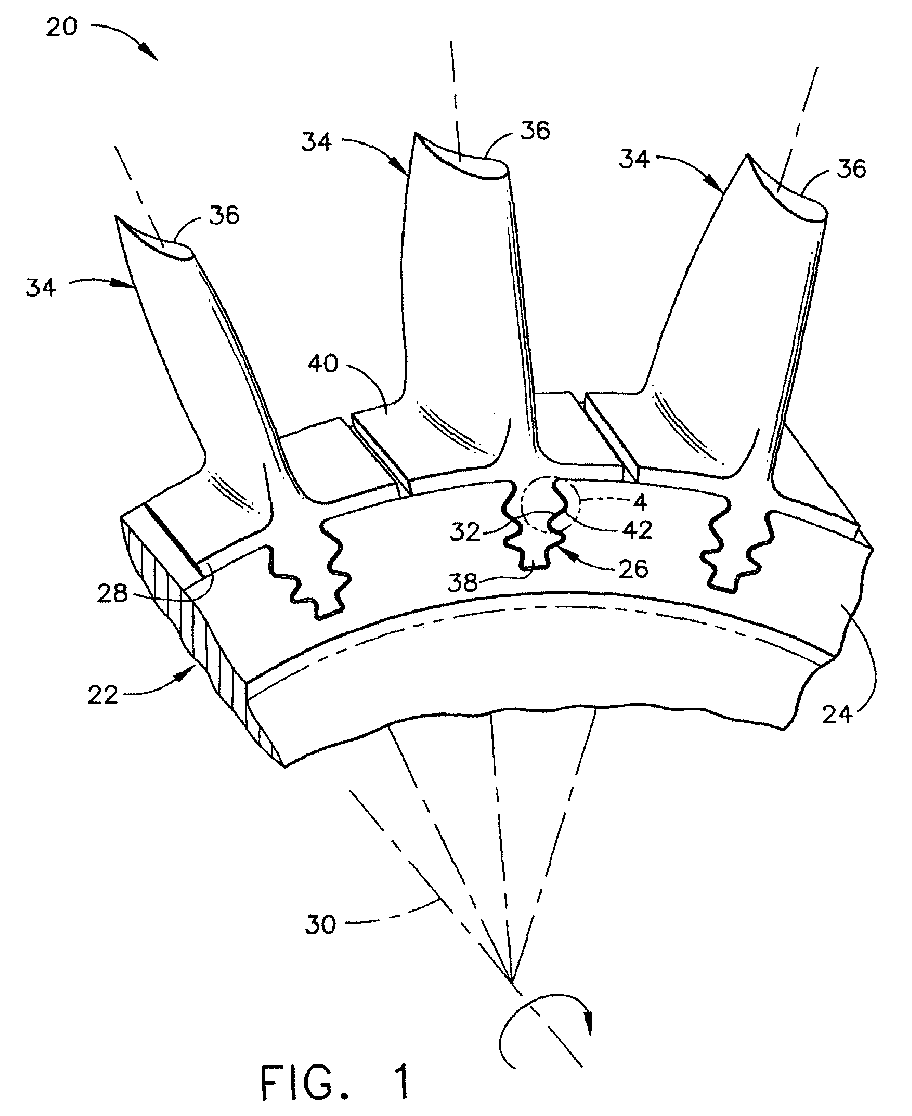
- FIG. 1 depicts a rotating structure 20 of a gas turbine engine.
- the rotating structure 20 includes a rotor disk 22 having a hub 24 with a plurality of hub slots 26 in a periphery 28 of the hub 24.
- the rotor disk 22 rotates on a shaft (not shown) about a rotation axis 30.
- Each hub slot 26 has a hub slot surface 32.
- Each rotor blade 34 has an airfoil 36 which compresses air and pumps it axially through the gas turbine engine as the rotor disk 22 turns about the rotation axis 30, and a root 38 at one end of the airfoil 36.
- a transversely extending platform 40 separates the root 38 from the airfoil 36.
- the root 38 of each of the rotor blades 34 has a root surface 42 that is shaped and sized to be received in one of the hub slots 26 of the rotor disk 22.
- the root surface 42 has the illustrated shape, termed a "dovetail" or "fir tree” shape. During service when the gas turbine engine is operating, the root surface 42 rubs against the hub slot surface 32, leading to fretting wear and thence to roughening of the surfaces and possibly fatigue cracking, in the absence of an approach such as that discussed herein.
- the rotor disk 22 may be a compressor disk, and the rotor blades 34 are compressor blades.
- the compressor disk and the compressor blades are typically made of titanium-base or nickel-base alloys.
- the rotor disk 22 may instead be a fan disk, and the rotor blades 34 are fan blades.
- the fan disk and the fan blades are typically made of titanium-base alloys.
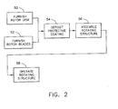
- FIG. 2 shows a method for providing the rotating structure 20.
- the rotor disk 22 is furnished, step 50, and the rotor blades 34 (without a protective coating as described below) are furnished, step 52.
- Steps 50 and 52 are known in the art.
- a protective coating is deposited, step 54, at a location which will, upon assembly of the rotor blades 34 to the rotor disk 22, be disposed between the root 38 of each rotor blade 34 and the respective hub slot surface 32.
- the deposition 54 is accomplished by a wire arc spray process.
- Wire arc spray processes and apparatus are known in the art.
- Figure 3 generally depicts a preferred form of the wire arc spray apparatus and its use.
- a spray apparatus 60 includes two continuously fed wire electrodes 62 of the material that is to be deposited and whose composition will be discussed subsequently.
- a voltage of from about 25 to about 35 volts is created between the two wire electrodes 62.
- a resulting arc 64 between the tips of the two wire electrodes 62 produces a plasma in this region.
- the wire electrodes 62 are melted by this plasma.
- a flow 66 of compressed gas such as nitrogen, argon, hydrogen, or, preferably, air, flows through this arc 64 and propels the droplets of molten metal as a jet 68 against a substrate 70, depositing a coating 72 of the metal of the wire electrodes 62 on the substrate 68.
- compressed gas such as nitrogen, argon, hydrogen, or, preferably, air
- the wire arc spray process and apparatus 60 have important features that produce a highly desirable coating 70 on the substrate 68.
- the arc 64 is struck between the two wire electrodes 62 (or between the wire and a cathode within the apparatus in other forms of the wire arc spray apparatus) and the hot arc is formed within the spray apparatus 60.
- an arc is struck between the spray apparatus and the substrate, so that a plasma is formed and much of the energy consumed by the apparatus is used to heat the substrate.
- the arc and its energy preferably remain within the spray apparatus 60 itself.
- the present approach uses only about 1/8 of the energy used by other thermal spray processes, a desirable feature for process economics.
- the coating 72 experiences less of a differential thermal strain upon cooling, because the substrate is not heated to as high a temperature as used for other thermal spray processes such as plasma spray (air or vacuum), physical vapor deposition, high velocity oxyfuel (HVOF) deposition, and D-gun (detonation gun).
- plasma spray air or vacuum
- physical vapor deposition high velocity oxyfuel (HVOF) deposition
- D-gun detonation gun
- wire arc spray process uses only compressed air, nitrogen, or other gas that does not ignite, as distinct from a hydrocarbon gas or hydrogen or the like, there is a reduced likelihood of the formation of undesirable phases in the deposited coating.
- the deposition of coatings by the wire arc spray process is inexpensive as compared with other techniques. There are fewer control variables in the wire arc spray process, and it is safer to operate than alternative approaches.
- the wire electrodes 62 are made of a protective alloy, and this same protective alloy is deposited as the coating 72.
- the protective alloy comprises, in weight percent, from about 6.0 to about 8.5 percent aluminum, from 0 to about 0.5 percent manganese, from 0 to about 0.2 percent zinc, from 0 to about 0.1 percent silicon, from 0 to about 0.1 percent iron, from 0 to about 0.02 percent lead, remainder copper and impurities.
- the protective alloy consists essentially of, in weight percent, from about 6.0 to about 8.5 percent aluminum, from 0 to about 0.5 percent manganese, from 0 to about 0.2 percent zinc, from 0 to about 0.1 percent silicon, from 0 to about 0.1 percent iron, from 0 to about 0.02 percent lead, remainder copper and impurities.
- This alloy termed an aluminum bronze, provides protection for the surfaces 42 and 32.
- composition of the protective alloy may not be substantially outside of these compositional limits.
- the compositional limits are selected cooperatively to yield the desirable properties that will be discussed subsequently, particularly in relation to Figures 7-10.
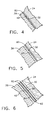
- Figures 4-6 depict three embodiments of interest for the application of a protective coating 80 of the protective alloy.
- the separation between the root 38 and the hub 24 is exaggerated, so that the locations of the protective coating and the other elements may be seen clearly.
- the various elements are much more closely spaced, and usually are contacting each other.
- the protective coating 80 is deposited upon the root surface 42. This approach is preferred, because the deposition may be accomplished more easily and uniformly than in the case wherein the protective coating 80 is applied inside the hub slot onto the hub slot surface 32, as in Figure 5.
- a shim 82 is provided and coated on one or both shim surfaces 84 with the protective coating 80.
- the shim 82 may be made of a different material than the root 38 and than the hub 24.
- the protective coating 80 is preferably from about 0.003 to about 0.020 inch thick. If the coating is too thin, the coating structure breaks down. If the coating is too thick, the cohesive strength between the coating and the substrate is unacceptably reduced.
- step 54 of Figure 2 the rotating structure 20 is assembled, step 56.
- the root 38 of each rotor blade 34 is slid into the respective hub slot 26.
- the protective coating 80 is located between the hub slot surface 32 and the root surface 42.
- the rotating structure 20 is thereafter assembled with the remainder of the gas turbine engine and operated under service conditions, step 58.
- the service temperature of the root 38 is typically from about 75°F to about 350°F..
- the lowest root service temperatures are found in the bypass fans, while higher service temperatures are found in the compressor stages.
- the temperatures of the roots 38 become successively higher for the higher pressure compressor stages.
- the present approach is particularly effective for articles to be used within this temperature range.
- the present approach has been reduced to practice and evaluated in comparative testing with an approach where a protective layer of 10 weight percent, balance copper (10 percent aluminum bronze) was applied by a plasma spray.
- the substrate was shot-peened titanium-6 aluminum-4 vanadium (by weight) alloy.
- Figures 7-8 illustrate comparative test results. As seen in Figure 7, the bond between the protective coating 80 of the present composition and deposition technique, and the substrate 70 to which it is applied, is stronger than that produced between a 10 percent aluminum bronze (copper-10 weight percent aluminum, and small amounts of other elements) protective coating and the substrate for a plasma-sprayed deposition approach.
- a 10 percent aluminum bronze copper-10 weight percent aluminum, and small amounts of other elements
- Figure 8 presents the coefficient of friction of the respective coatings as a function of the number of cycles of wear.
- EWA or "electric wire arc" refers to the present approach, and P refers to plasma spray.
- the number in each legend is the coating thickness in thousandths of an inch, e.g., .003 means 0.003 inches thick.
- the substrate was shot-peened titanium-6 aluminum-4 vanadium (by weight) alloy.
- the contact pressure was 135,000 pounds per square inch
- the sliding stroke was 0.009 inches
- the frequency of the stroke was 60 cycles per minute. No lubricant was used.
- the specimens prepared using the present approach had a uniformly low coefficient of friction of 0.1-0.2 that was maintained for extended numbers of cycles.
- the specimens prepared using the 10 percent aluminum bronze and plasma spray had much higher coefficients of friction, which varied considerably during the course of the testing.
Landscapes
- Engineering & Computer Science (AREA)
- Chemical & Material Sciences (AREA)
- Physics & Mathematics (AREA)
- Plasma & Fusion (AREA)
- Mechanical Engineering (AREA)
- Chemical Kinetics & Catalysis (AREA)
- Materials Engineering (AREA)
- Metallurgy (AREA)
- Organic Chemistry (AREA)
- General Engineering & Computer Science (AREA)
- Structures Of Non-Positive Displacement Pumps (AREA)
- Coating By Spraying Or Casting (AREA)
Abstract
Description
- This invention relates to a gas turbine engine and, more particularly, to the prevention of wear damage between the rotor blades and the rotor disk in the compressor and fan sections of the engine.
- In an aircraft gas turbine (jet) engine, air is drawn into the front of the engine, compressed by a shaft-mounted compressor, and mixed with fuel. The mixture is combusted, and the resulting hot combustion gases are passed through a turbine mounted on the same shaft. The flow of gas turns the turbine by contacting an airfoil portion of the turbine blade, which turns the shaft and provides power to the compressor. The hot exhaust gases flow from the back of the engine, driving it and the aircraft forward. There may additionally be a bypass fan that forces air around the center core of the engine, driven by a shaft extending from the turbine section.
- The compressor and the bypass fan are both rotating structures in which blades extend radially outwardly from a rotor disk. In most cases, the blades are made of a different material than the rotor disk, so that they are manufactured separately and then affixed to the rotor disk. That is, compressor blades are manufactured and mounted to a compressor rotor disk, and fan blades are manufactured and mounted to a fan rotor disk.
- In one approach that is widely used, each blade has an airfoil-shaped region and a root at one end thereof. The root is in the form of a dovetail structure. The rotor disk has corresponding hub slots therein. The dovetail structure of each root slides into its respective hub slot to affix the blade to the rotor disk.
- When the gas turbine engine is operated, there is a high-frequency, low amplitude relative movement between the root and the surface of the hub slot. This movement produces wear damage, of a type typically termed "fretting wear", to the root or to the hub slot. The fretting wear may lead to the initiation of fatigue cracks which in turn lead to the need for premature inspections of the components, or in extreme cases may lead to failure.
- This problem has long been a concern to aircraft engine manufacturers. A variety of anti-wear coatings have been developed. However, these coatings have not been entirely satisfactory for compressor and fan rotor applications. There is a need for a more suitable protective coatings. The present invention fulfills this need, and further provides related advantages.
- The present invention includes a method for providing a rotating structure of a gas turbine engine. The contact between the rotor disk and the rotor blades is protected by a protective coating that reduces friction and wear between these components. The result is an extended life without wear-based fatigue damage and failures.
- A method for providing a rotating structure of a gas turbine engine comprises the steps of furnishing a rotor disk comprising a hub with a plurality of hub slots in a periphery of the hub. Each hub slot has a hub slot surface. A plurality of rotor blades are furnished, wherein each rotor blade comprises an airfoil, and a root at one end of the airfoil. The root is shaped and sized to be received in one of the hub slots of the rotor disk. A protective coating is deposited at a location which will be, upon assembly, disposed between the root of each rotor blade and the respective hub slot surface. The deposition is performed by a wire arc spray process, preferably a compressed-air wire arc spray process. The protective coating is a protective alloy comprising (preferably consisting essentially of), in weight percent, from about 6.0 to about 8.5 percent aluminum, from 0 to about 0.5 percent manganese, from 0 to about 0.2 percent zinc, from 0 to about 0.1 percent silicon, from 0 to about 0.1 percent iron, from 0 to about 0.02 percent lead, remainder copper and impurities. The protective coating is preferably from about 0.003 to about 0.020 inch thick. The roots of the rotor blades are assembled into the respective hub slots of the rotor disk to form the rotating structure.
- The rotor disk may be a compressor disk, and the rotor blades are compressor blades. Alternatively, the rotor disk may be a fan disk, and the rotor blades are fan blades. Preferably, the hub of the rotor disk is made of a titanium alloy.
- The protective coating may be deposited on the root, or on the hub slot surface, or both. Alternatively, the protective coating may be deposited on a shim that is subsequently positioned during assembly between the root and the hub slot surface.
- The rotating structure is thereafter operated such that the root is at a temperature of from about 75°F to about 350°F.
- In a preferred form, a method for providing a rotating structure of a gas turbine engine comprises the steps of furnishing a set of rotor blades, with each rotor blade comprising an airfoil, and a root at one end of the airfoil. A protective coating having the protective alloy composition set forth above is deposited on the root of each rotor blade by a wire arc spray process. The rotor blades are assembled into the hub slots of the rotor disk and subsequently operated.
- The present approach yields a low-friction, low-wear interface between the root of the blade and the hub slot surface of the rotor disk. The wire arc spray process produces good bonding between the protective coating and the substrate, with a relatively low-temperature deposition technique that does not overly heat the substrate or produce high differential thermal stresses between the substrate and the protective coating. The preferred compressed-air wire arc spray process has the additional advantage that no contaminants such as hydrocarbons are introduced into the deposited protective coating.
- The invention will now be described in greater detail, by way of example, with reference to the drawings, in which:-
- Figure 1 is a perspective view of a portion of a rotor disk with rotor blades mounted thereto;
- Figure 2 is a block flow diagram of an approach for practicing the invention;
- Figure 3 is a schematic depiction of a wire arc spray apparatus;
- Figure 4 is a detail of the region of the root and the hub slot of Figure 1, taken
in
region 4 and showing a first embodiment of the invention; - Figure 5 is a detail like that of Figure 4, showing a second embodiment of the invention;
- Figure 6 is a detail like that of Figure 4, showing a third embodiment of the invention;
- Figure 7 is a graph of tensile strength as a function of thickness, for the bond between the protective coating and the substrate, for the present approach and for a first prior approach; and
- Figure 8 is a graph of coefficient of friction as a function of number of cycles of wear, for the protective coating of the present approach and for the first prior approach.
-
- Figure 1 depicts a rotating
structure 20 of a gas turbine engine. Therotating structure 20 includes arotor disk 22 having ahub 24 with a plurality ofhub slots 26 in aperiphery 28 of thehub 24. Therotor disk 22 rotates on a shaft (not shown) about arotation axis 30. Eachhub slot 26 has ahub slot surface 32. There are a plurality (three of which are illustrated in this segmented view) ofrotor blades 34 extending around theperiphery 28 of thehub 24, one for eachhub slot 26. Eachrotor blade 34 has anairfoil 36 which compresses air and pumps it axially through the gas turbine engine as therotor disk 22 turns about therotation axis 30, and aroot 38 at one end of theairfoil 36. Typically, a transversely extendingplatform 40 separates theroot 38 from theairfoil 36. Theroot 38 of each of therotor blades 34 has aroot surface 42 that is shaped and sized to be received in one of thehub slots 26 of therotor disk 22. Most commonly, theroot surface 42 has the illustrated shape, termed a "dovetail" or "fir tree" shape. During service when the gas turbine engine is operating, theroot surface 42 rubs against thehub slot surface 32, leading to fretting wear and thence to roughening of the surfaces and possibly fatigue cracking, in the absence of an approach such as that discussed herein. - The
rotor disk 22 may be a compressor disk, and therotor blades 34 are compressor blades. The compressor disk and the compressor blades are typically made of titanium-base or nickel-base alloys. Therotor disk 22 may instead be a fan disk, and therotor blades 34 are fan blades. The fan disk and the fan blades are typically made of titanium-base alloys. - Figure 2 shows a method for providing the rotating
structure 20. Therotor disk 22 is furnished,step 50, and the rotor blades 34 (without a protective coating as described below) are furnished,step 52.Steps step 54, at a location which will, upon assembly of therotor blades 34 to therotor disk 22, be disposed between theroot 38 of eachrotor blade 34 and the respectivehub slot surface 32. - The
deposition 54 is accomplished by a wire arc spray process. Wire arc spray processes and apparatus are known in the art. Figure 3 generally depicts a preferred form of the wire arc spray apparatus and its use. Aspray apparatus 60 includes two continuously fedwire electrodes 62 of the material that is to be deposited and whose composition will be discussed subsequently. A voltage of from about 25 to about 35 volts is created between the twowire electrodes 62. A resultingarc 64 between the tips of the twowire electrodes 62 produces a plasma in this region. Thewire electrodes 62 are melted by this plasma. Aflow 66 of compressed gas, such as nitrogen, argon, hydrogen, or, preferably, air, flows through thisarc 64 and propels the droplets of molten metal as ajet 68 against asubstrate 70, depositing acoating 72 of the metal of thewire electrodes 62 on thesubstrate 68. - The wire arc spray process and
apparatus 60 have important features that produce a highlydesirable coating 70 on thesubstrate 68. Thearc 64 is struck between the two wire electrodes 62 (or between the wire and a cathode within the apparatus in other forms of the wire arc spray apparatus) and the hot arc is formed within thespray apparatus 60. In many other thermal spray processes, an arc is struck between the spray apparatus and the substrate, so that a plasma is formed and much of the energy consumed by the apparatus is used to heat the substrate. In the present case, the arc and its energy preferably remain within thespray apparatus 60 itself. The present approach uses only about 1/8 of the energy used by other thermal spray processes, a desirable feature for process economics. From the standpoint of the part being coated (i.e., the substrate 70) and thecoating 72 itself, there is less heating of the part being coated so that it stays at a lower temperature than is the case for other approaches. Thecoating 72 experiences less of a differential thermal strain upon cooling, because the substrate is not heated to as high a temperature as used for other thermal spray processes such as plasma spray (air or vacuum), physical vapor deposition, high velocity oxyfuel (HVOF) deposition, and D-gun (detonation gun). - Additionally, when the wire arc spray process uses only compressed air, nitrogen, or other gas that does not ignite, as distinct from a hydrocarbon gas or hydrogen or the like, there is a reduced likelihood of the formation of undesirable phases in the deposited coating. The deposition of coatings by the wire arc spray process is inexpensive as compared with other techniques. There are fewer control variables in the wire arc spray process, and it is safer to operate than alternative approaches.
- In the present approach, the
wire electrodes 62 are made of a protective alloy, and this same protective alloy is deposited as thecoating 72. The protective alloy comprises, in weight percent, from about 6.0 to about 8.5 percent aluminum, from 0 to about 0.5 percent manganese, from 0 to about 0.2 percent zinc, from 0 to about 0.1 percent silicon, from 0 to about 0.1 percent iron, from 0 to about 0.02 percent lead, remainder copper and impurities. Preferably, the protective alloy consists essentially of, in weight percent, from about 6.0 to about 8.5 percent aluminum, from 0 to about 0.5 percent manganese, from 0 to about 0.2 percent zinc, from 0 to about 0.1 percent silicon, from 0 to about 0.1 percent iron, from 0 to about 0.02 percent lead, remainder copper and impurities. This alloy, termed an aluminum bronze, provides protection for thesurfaces - The composition of the protective alloy may not be substantially outside of these compositional limits. The compositional limits are selected cooperatively to yield the desirable properties that will be discussed subsequently, particularly in relation to Figures 7-10.
- Figures 4-6 depict three embodiments of interest for the application of a
protective coating 80 of the protective alloy. In Figures 4-6, the separation between theroot 38 and thehub 24 is exaggerated, so that the locations of the protective coating and the other elements may be seen clearly. After assembly, the various elements are much more closely spaced, and usually are contacting each other. In the approach of Figure 4, theprotective coating 80 is deposited upon theroot surface 42. This approach is preferred, because the deposition may be accomplished more easily and uniformly than in the case wherein theprotective coating 80 is applied inside the hub slot onto thehub slot surface 32, as in Figure 5. In the approach of Figure 6, ashim 82 is provided and coated on one or both shim surfaces 84 with theprotective coating 80. Theshim 82 may be made of a different material than theroot 38 and than thehub 24. - In each case, the
protective coating 80 is preferably from about 0.003 to about 0.020 inch thick. If the coating is too thin, the coating structure breaks down. If the coating is too thick, the cohesive strength between the coating and the substrate is unacceptably reduced. - After the
protective coating 80 is deposited, step 54 of Figure 2, the rotatingstructure 20 is assembled,step 56. In assembly, theroot 38 of eachrotor blade 34 is slid into therespective hub slot 26. Theprotective coating 80 is located between thehub slot surface 32 and theroot surface 42. - The rotating
structure 20 is thereafter assembled with the remainder of the gas turbine engine and operated under service conditions,step 58. In the present case, the service temperature of theroot 38 is typically from about 75°F to about 350°F.. The lowest root service temperatures are found in the bypass fans, while higher service temperatures are found in the compressor stages. The temperatures of theroots 38 become successively higher for the higher pressure compressor stages. The present approach is particularly effective for articles to be used within this temperature range. - The present approach has been reduced to practice and evaluated in comparative testing with an approach where a protective layer of 10 weight percent, balance copper (10 percent aluminum bronze) was applied by a plasma spray. In each case, the substrate was shot-peened titanium-6 aluminum-4 vanadium (by weight) alloy.
- Figures 7-8 illustrate comparative test results. As seen in Figure 7, the bond between the
protective coating 80 of the present composition and deposition technique, and thesubstrate 70 to which it is applied, is stronger than that produced between a 10 percent aluminum bronze (copper-10 weight percent aluminum, and small amounts of other elements) protective coating and the substrate for a plasma-sprayed deposition approach. - Figure 8 presents the coefficient of friction of the respective coatings as a function of the number of cycles of wear. (In the legend for Figure 8, EWA or "electric wire arc" refers to the present approach, and P refers to plasma spray. The number in each legend is the coating thickness in thousandths of an inch, e.g., .003 means 0.003 inches thick.) In each case, the substrate was shot-peened titanium-6 aluminum-4 vanadium (by weight) alloy. The contact pressure was 135,000 pounds per square inch, the sliding stroke was 0.009 inches, and the frequency of the stroke was 60 cycles per minute. No lubricant was used. The specimens prepared using the present approach had a uniformly low coefficient of friction of 0.1-0.2 that was maintained for extended numbers of cycles. The specimens prepared using the 10 percent aluminum bronze and plasma spray had much higher coefficients of friction, which varied considerably during the course of the testing.
- For the sake of good order, various aspects of the invention are set out in the following clauses:-
- 1. A method for providing a rotating structure (20) of a gas turbine engine
comprising the steps of:
- furnishing a rotor disk (22) comprising a hub (24) with a plurality of hub slots (26) in a periphery of the hub (24), each hub slot (26) having a hub slot surface (32);
- furnishing a plurality of rotor blades (34), wherein each rotor blade (34) comprises
- an airfoil (36), and
- a root (38) at one end of the airfoil (36), the root (38) being shaped and sized to be received in one of the hub slots (26) of the rotor disk (22);
- depositing a protective coating (80) at a location which will be, upon assembly, disposed between the root (38) of each rotor blade (34) and the respective hub slot surface (32) by a wire arc spray process, the protective coating (80) being a protective alloy comprising, in weight percent, from about 6.0 to about 8.5 percent aluminum, from 0 to about 0.5 percent manganese, from 0 to about 0.2 percent zinc, from 0 to about 0.1 percent silicon, from 0 to about 0.1 percent iron, from 0 to about 0.02 percent lead, remainder copper and impurities; and
- assembling the roots (38) of the rotor blades (34) into the respective hub slots (26) of the rotor disk (22) to form the rotating structure (20).
- 2. The method of clause 1, wherein the step of furnishing the rotor disk
(22) includes the step of
- furnishing a compressor disk, and wherein the step of furnishing the rotor blades (34) includes the step of furnishing compressor blades.
- 3. The method of clause 1, wherein the step of furnishing the rotor disk
(22) includes the step of
- furnishing a fan disk, and wherein the step of furnishing the rotor blades (34) includes the step of furnishing fan blades.
- 4. The method of clause 1, wherein the step of providing the rotor disk (22) includes the step of furnishing the hub (24) made of a titanium alloy.
- 5. The method of clause 1, wherein the step of depositing the protective coating (80) includes the step of depositing the protective coating (80) wherein the protective alloy consists essentially of, in weight percent, from about 6.0 to about 8.5 percent aluminum, from 0 to about 0.5 percent manganese, from 0 to about 0.2 percent zinc, from 0 to about 0.1 percent silicon, from 0 to about 0.1 percent iron, from 0 to about 0.02 percent lead, remainder copper and impurities.
- 6. The method of clause 1, wherein the step of depositing the protective coating (80) includes the step of depositing the protective coating (80) on the root (38).
- 7. The method of clause 1, wherein the step of depositing the protective coating (80) includes the step of depositing the protective coating (80) on the hub slot surface (32).
- 8. The method of clause 1, wherein the step of depositing the protective
coating (80) includes the steps of
- furnishing a shim (82) sized to be positioned between the root (38) and the hub slot surface (32), and
- depositing the protective coating (80) on a surface of the shim (82).
- 9. The method of clause 1, wherein the step of depositing the protective coating (80) includes the step of spraying the protective coating (80) using a compressed-air wire arc spray process.
- 10. The method of clause 1, wherein the step of depositing the protective coating (80) includes the step of depositing the protective coating (80) in a thickness of from about 0.003 to about 0.020 inch.
- 11. The method of clause 1, including an additional step, after the step of assembling, of operating the rotating structure (20) such that the root (38) is at a temperature of from about 75°F to about 350°F.
- 12. A method for providing a rotating structure (20) of a gas turbine engine
comprising the steps of:
- furnishing a set of rotor blades (34), each rotor blade (34) comprising an airfoil (36), and
- a root (38) at one end of the airfoil (36); and
- depositing a protective coating (80) on the root (38) of each rotor blade (34) by a wire arc spray process, the protective coating (80) being a protective alloy comprising, in weight percent, from about 6.0 to about 8.5 percent aluminum, from 0 to about 0.5 percent manganese, from 0 to about 0.2 percent zinc, from 0 to about 0.1 percent silicon, from 0 to about 0.1 percent iron, from 0 to about 0.02 percent lead, remainder copper and impurities.
- 13. The method of clause 12, including an additional step, after the step of depositing the protective coating (80), of assembling the roots (38) of the rotor blades (34) into a set of slots on a hub (24) of a rotor disk (22) to form a rotating structure (20).
- 14. The method of clause 13, including an additional step, after the step of assembling, of operating the rotating structure (20) such that the root (38) is at a temperature of from about 75°F to about 350°F.
- 15. The method of clause 13, wherein the step of assembling includes the step of furnishing the hub (24) made of a titanium alloy.
- 16. The method of clause 12, wherein the step of furnishing a set of rotor blades (34) includes the step of furnishing compressor blades.
- 17. The method of clause 12, wherein the step of furnishing a set of rotor blades (34) includes the step of furnishing fan blades.
- 18. The method of clause 12, wherein the step of depositing the protective coating (80) includes the step of depositing the protective coating (80) wherein the protective alloy consists essentially of, in weight percent, from about 6.0 to about 8.5 percent aluminum, from 0 to about 0.5 percent manganese, from 0 to about 0.2 percent zinc, from 0 to about 0.1 percent silicon, from 0 to about 0.1 percent iron, from 0 to about 0.02 percent lead, remainder copper and impurities.
- 19. The method of clause 12, wherein the step of depositing the protective coating (80) includes the step of spraying the protective coating (80) using a compressed-air wire arc spray process.
- 20. The method of clause 12, wherein the step of depositing the protective coating (80) includes the step of depositing the protective coating (80) in a thickness of from about 0.003 to about 0.020 inch.
-
Claims (10)
- A method for providing a rotating structure (20) of a gas turbine engine comprising the steps of:furnishing a rotor disk (22) comprising a hub (24) with a plurality of hub slots (26) in a periphery of the hub (24), each hub slot (26) having a hub slot surface (32);furnishing a plurality of rotor blades (34), wherein each rotor blade (34) comprisesan airfoil (36), anda root (38) at one end of the airfoil (36), the root (38) being shaped and sized to be received in one of the hub slots (26) of the rotor disk (22);depositing a protective coating (80) at a location which will be, upon assembly, disposed between the root (38) of each rotor blade (34) and the respective hub slot surface (32) by a wire arc spray process, the protective coating (80) being a protective alloy comprising, in weight percent, from about 6.0 to about 8.5 percent aluminum, from 0 to about 0.5 percent manganese, from 0 to about 0.2 percent zinc, from 0 to about 0.1 percent silicon, from 0 to about 0.1 percent iron, from 0 to about 0.02 percent lead, remainder copper and impurities; andassembling the roots (38) of the rotor blades (34) into the respective hub slots (26) of the rotor disk (22) to form the rotating structure (20).
- The method of claim 1, wherein the step of furnishing the rotor disk (22) includes the step ofwherein the step of furnishing the rotor blades (34) includes the step of furnishing compressor blades.furnishing a compressor disk, and
- The method of claim 1, wherein the step of furnishing the rotor disk (22) includes the step ofwherein the step of furnishing the rotor blades (34) includes the step of furnishing fan blades.furnishing a fan disk, and
- The method of claim 1, 2 or 3, wherein the step of providing the rotor disk (22) includes the step of furnishing the hub (24) made of a titanium alloy.
- The method of any preceding claim 1, wherein the step of depositing the protective coating (80) includes the step of depositing the protective coating (80) wherein the protective alloy consists essentially of, in weight percent, from about 6.0 to about 8.5 percent aluminum, from 0 to about 0.5 percent manganese, from 0 to about 0.2 percent zinc, from 0 to about 0.1 percent silicon, from 0 to about 0.1 percent iron, from 0 to about 0.02 percent lead, remainder copper and impurities.
- A method for providing a rotating structure (20) of a gas turbine engine comprising the steps of:furnishing a set of rotor blades (34), each rotor blade (34) comprising an airfoil (36), anda root (38) at one end of the airfoil (36); anddepositing a protective coating (80) on the root (38) of each rotor blade (34) by a wire arc spray process, the protective coating (80) being a protective alloy comprising, in weight percent, from about 6.0 to about 8.5 percent aluminum, from 0 to about 0.5 percent manganese, from 0 to about 0.2 percent zinc, from 0 to about 0.1 percent silicon, from 0 to about 0.1 percent iron, from 0 to about 0.02 percent lead, remainder copper and impurities.
- The method of claim 6, including an additional step, after the step of depositing the protective coating (80), of assembling the roots (38) of the rotor blades (34) into a set of slots on a hub (24) of a rotor disk (22) to form a rotating structure (20).
- The method of claim 7, including an additional step, after the step of assembling, of operating the rotating structure (20) such that the root (38) is at a temperature of from about 75°F to about 350°F.
- The method of claim 7, wherein the step of assembling includes the step of furnishing the hub (24) made of a titanium alloy.
- The method of any of claims 6 to 9, wherein the step of furnishing a set of rotor blades (34) includes the step of furnishing compressor blades.
Applications Claiming Priority (2)
| Application Number | Priority Date | Filing Date | Title |
|---|---|---|---|
| US10/141,573 US6751863B2 (en) | 2002-05-07 | 2002-05-07 | Method for providing a rotating structure having a wire-arc-sprayed aluminum bronze protective coating thereon |
| US141573 | 2002-05-07 |
Publications (1)
| Publication Number | Publication Date |
|---|---|
| EP1361339A1 true EP1361339A1 (en) | 2003-11-12 |
Family
ID=29249817
Family Applications (1)
| Application Number | Title | Priority Date | Filing Date |
|---|---|---|---|
| EP03252808A Withdrawn EP1361339A1 (en) | 2002-05-07 | 2003-05-06 | Method for producing a bladed rotor for a gas turbine engine having an aluminium bronze protective coating |
Country Status (2)
| Country | Link |
|---|---|
| US (1) | US6751863B2 (en) |
| EP (1) | EP1361339A1 (en) |
Cited By (7)
| Publication number | Priority date | Publication date | Assignee | Title |
|---|---|---|---|---|
| EP1674590A1 (en) | 2004-12-21 | 2006-06-28 | Linde Aktiengesellschaft | Use of a gas mixture and method for electric arc spraying |
| US7275278B1 (en) * | 2002-09-19 | 2007-10-02 | Martin W Andrew | Grill cleaning device |
| EP2014873A1 (en) * | 2007-07-13 | 2009-01-14 | Snecma | Tinsel for turbomachine vane |
| DE102009049707A1 (en) * | 2009-10-17 | 2011-07-28 | MTU Aero Engines GmbH, 80995 | Method for producing a rotor or stator blade and such a blade |
| EP1726831A3 (en) * | 2005-05-24 | 2012-04-11 | General Electric Company | Coated forward stub shaft dovetail slot |
| WO2014137438A1 (en) * | 2013-03-07 | 2014-09-12 | United Technologies Corporation | Aluminum fan blades with root wear mitigation |
| EP3293357A1 (en) * | 2016-09-08 | 2018-03-14 | Siemens Aktiengesellschaft | Turbine blade base with coating |
Families Citing this family (16)
| Publication number | Priority date | Publication date | Assignee | Title |
|---|---|---|---|---|
| DE10345827A1 (en) * | 2003-10-02 | 2005-05-04 | Daimler Chrysler Ag | Process for coating metallic substrates with oxidizing materials by means of arc wire spraying |
| US20060121302A1 (en) * | 2004-12-07 | 2006-06-08 | Erickson Gary C | Wire-arc spraying of a zinc-nickel coating |
| US7836593B2 (en) | 2005-03-17 | 2010-11-23 | Siemens Energy, Inc. | Cold spray method for producing gas turbine blade tip |
| US7836591B2 (en) * | 2005-03-17 | 2010-11-23 | Siemens Energy, Inc. | Method for forming turbine seal by cold spray process |
| DE102005054172A1 (en) * | 2005-11-14 | 2007-05-16 | Mtu Aero Engines Gmbh | Shovel of a turbomachine |
| US20080066288A1 (en) * | 2006-09-08 | 2008-03-20 | General Electric Company | Method for applying a high temperature anti-fretting wear coating |
| FR2918703B1 (en) * | 2007-07-13 | 2009-10-16 | Snecma Sa | ROTOR ASSEMBLY OF TURBOMACHINE |
| US20100080921A1 (en) * | 2008-09-30 | 2010-04-01 | Beardsley M Brad | Thermal spray coatings for reduced hexavalent and leachable chromuim byproducts |
| US9719353B2 (en) | 2011-04-13 | 2017-08-01 | Rolls-Royce Corporation | Interfacial diffusion barrier layer including iridium on a metallic substrate |
| US10309232B2 (en) * | 2012-02-29 | 2019-06-04 | United Technologies Corporation | Gas turbine engine with stage dependent material selection for blades and disk |
| US20130244052A1 (en) * | 2012-03-18 | 2013-09-19 | Michael A Mullock | Forming a Metallic Cladding on an Architectural Component |
| US9410439B2 (en) * | 2012-09-14 | 2016-08-09 | United Technologies Corporation | CMC blade attachment shim relief |
| FR3014477B1 (en) * | 2013-12-06 | 2016-01-08 | Turbomeca | ROTOR IN AUBES |
| EP2918705B1 (en) | 2014-03-12 | 2017-05-03 | Rolls-Royce Corporation | Coating including diffusion barrier layer including iridium and oxide layer and method of coating |
| US10087948B2 (en) * | 2015-03-30 | 2018-10-02 | United Technologies Corporation | Fan blade and method of covering a fan blade root portion |
| US11952916B2 (en) * | 2020-08-14 | 2024-04-09 | Rtx Corporation | Self-lubricating blade root/disk interface |
Citations (4)
| Publication number | Priority date | Publication date | Assignee | Title |
|---|---|---|---|---|
| US4196237A (en) * | 1976-07-19 | 1980-04-01 | Eutectic Corporation | High hardness copper-aluminum alloy flame spray powder |
| US5296057A (en) * | 1991-09-20 | 1994-03-22 | Hitachi, Ltd. | High abrasion resistant aluminum bronze alloy, and sliding members using same |
| US5580669A (en) * | 1994-02-17 | 1996-12-03 | United Technologies Corporation | Oxidation resistant coating for titanium alloys |
| EP0939197A2 (en) * | 1998-02-26 | 1999-09-01 | United Technologies Corporation | Coating inhibiting frictional wear between mating titanium alloy parts in a gas turbine engine |
Family Cites Families (13)
| Publication number | Priority date | Publication date | Assignee | Title |
|---|---|---|---|---|
| DE3236376C2 (en) | 1982-10-01 | 1986-06-19 | MTU Motoren- und Turbinen-Union München GmbH, 8000 München | Process for protecting metallic, force-fit paired machine parts from fretting corrosion |
| US4526839A (en) * | 1984-03-01 | 1985-07-02 | Surface Science Corp. | Process for thermally spraying porous metal coatings on substrates |
| US4741974A (en) * | 1986-05-20 | 1988-05-03 | The Perkin-Elmer Corporation | Composite wire for wear resistant coatings |
| JPS63219563A (en) * | 1987-03-10 | 1988-09-13 | Toyota Motor Corp | Manufacture of disk rotor |
| US4869936A (en) * | 1987-12-28 | 1989-09-26 | Amoco Corporation | Apparatus and process for producing high density thermal spray coatings |
| US5294462A (en) * | 1990-11-08 | 1994-03-15 | Air Products And Chemicals, Inc. | Electric arc spray coating with cored wire |
| US5312696A (en) | 1991-09-16 | 1994-05-17 | United Technologies Corporation | Method for reducing fretting wear between contacting surfaces |
| US5976704A (en) * | 1994-03-01 | 1999-11-02 | Ford Global Technologies, Inc. | Composite metallizing wire and method of using |
| US6001426A (en) * | 1996-07-25 | 1999-12-14 | Utron Inc. | High velocity pulsed wire-arc spray |
| US5791560A (en) * | 1996-12-09 | 1998-08-11 | Thermion, Inc. | Method and apparatus for spraying metal to form a coating |
| US5808270A (en) | 1997-02-14 | 1998-09-15 | Ford Global Technologies, Inc. | Plasma transferred wire arc thermal spray apparatus and method |
| US5820939A (en) * | 1997-03-31 | 1998-10-13 | Ford Global Technologies, Inc. | Method of thermally spraying metallic coatings using flux cored wire |
| US5958520A (en) | 1998-07-13 | 1999-09-28 | Ford Global Technologies, Inc. | Method of staggering reversal of thermal spray inside a cylinder bore |
-
2002
- 2002-05-07 US US10/141,573 patent/US6751863B2/en not_active Expired - Lifetime
-
2003
- 2003-05-06 EP EP03252808A patent/EP1361339A1/en not_active Withdrawn
Patent Citations (4)
| Publication number | Priority date | Publication date | Assignee | Title |
|---|---|---|---|---|
| US4196237A (en) * | 1976-07-19 | 1980-04-01 | Eutectic Corporation | High hardness copper-aluminum alloy flame spray powder |
| US5296057A (en) * | 1991-09-20 | 1994-03-22 | Hitachi, Ltd. | High abrasion resistant aluminum bronze alloy, and sliding members using same |
| US5580669A (en) * | 1994-02-17 | 1996-12-03 | United Technologies Corporation | Oxidation resistant coating for titanium alloys |
| EP0939197A2 (en) * | 1998-02-26 | 1999-09-01 | United Technologies Corporation | Coating inhibiting frictional wear between mating titanium alloy parts in a gas turbine engine |
Cited By (10)
| Publication number | Priority date | Publication date | Assignee | Title |
|---|---|---|---|---|
| US7275278B1 (en) * | 2002-09-19 | 2007-10-02 | Martin W Andrew | Grill cleaning device |
| EP1674590A1 (en) | 2004-12-21 | 2006-06-28 | Linde Aktiengesellschaft | Use of a gas mixture and method for electric arc spraying |
| EP1726831A3 (en) * | 2005-05-24 | 2012-04-11 | General Electric Company | Coated forward stub shaft dovetail slot |
| KR101329892B1 (en) * | 2005-05-24 | 2013-11-15 | 제너럴 일렉트릭 캄파니 | Coated forward stub shaft dovetail slot |
| EP2014873A1 (en) * | 2007-07-13 | 2009-01-14 | Snecma | Tinsel for turbomachine vane |
| FR2918702A1 (en) * | 2007-07-13 | 2009-01-16 | Snecma Sa | CLINKING FOR TURBOMACHINE BLADE |
| DE102009049707A1 (en) * | 2009-10-17 | 2011-07-28 | MTU Aero Engines GmbH, 80995 | Method for producing a rotor or stator blade and such a blade |
| US9132508B2 (en) | 2009-10-17 | 2015-09-15 | Mtu Aero Engines Gmbh | Method for producing a rotor or stator blade and such a blade |
| WO2014137438A1 (en) * | 2013-03-07 | 2014-09-12 | United Technologies Corporation | Aluminum fan blades with root wear mitigation |
| EP3293357A1 (en) * | 2016-09-08 | 2018-03-14 | Siemens Aktiengesellschaft | Turbine blade base with coating |
Also Published As
| Publication number | Publication date |
|---|---|
| US20030208904A1 (en) | 2003-11-13 |
| US6751863B2 (en) | 2004-06-22 |
Similar Documents
| Publication | Publication Date | Title |
|---|---|---|
| US6751863B2 (en) | Method for providing a rotating structure having a wire-arc-sprayed aluminum bronze protective coating thereon | |
| US7247348B2 (en) | Method for manufacturing a erosion preventative diamond-like coating for a turbine engine compressor blade | |
| US7378132B2 (en) | Method for applying environmental-resistant MCrAlY coatings on gas turbine components | |
| US8118561B2 (en) | Erosion- and impact-resistant coatings | |
| US9249670B2 (en) | Components with microchannel cooling | |
| US10005160B2 (en) | Repair methods for cooled components | |
| US8528208B2 (en) | Methods of fabricating a coated component using multiple types of fillers | |
| US6296447B1 (en) | Gas turbine component having location-dependent protective coatings thereon | |
| US20060222776A1 (en) | Environment-resistant platinum aluminide coatings, and methods of applying the same onto turbine components | |
| EP3480428B1 (en) | Abrasive airfoil tip and fabrication method thereof | |
| US20160153290A1 (en) | Gas turbine blade and method of protecting same | |
| EP3239475B1 (en) | Outer airseal abradable rub strip | |
| EP1897966A2 (en) | Method for applying a high temperature anti-fretting wear coating | |
| US20130078418A1 (en) | Components with cooling channels and methods of manufacture | |
| US20100055339A1 (en) | Method of forming molybdenum based wear resistant coating on a workpiece | |
| US7744986B2 (en) | Multilayered erosion resistant coating for gas turbines | |
| US11946389B2 (en) | Turbine rotor blade and contact surface manufacturing method | |
| CN113981356A (en) | Spraying powder particles for aeroengine sealing coating | |
| US6913839B2 (en) | Coated article having a quasicrystalline-ductile metal layered coating with high particle-impact damage resistance, and its preparation and use | |
| Kanao et al. | Application of corrosion resistant coatings to gas turbines |
Legal Events
| Date | Code | Title | Description |
|---|---|---|---|
| PUAI | Public reference made under article 153(3) epc to a published international application that has entered the european phase |
Free format text: ORIGINAL CODE: 0009012 |
|
| AK | Designated contracting states |
Kind code of ref document: A1 Designated state(s): AT BE BG CH CY CZ DE DK EE ES FI FR GB GR HU IE IT LI LU MC NL PT RO SE SI SK TR |
|
| AX | Request for extension of the european patent |
Extension state: AL LT LV MK |
|
| 17P | Request for examination filed |
Effective date: 20040512 |
|
| AKX | Designation fees paid |
Designated state(s): DE FR GB |
|
| 17Q | First examination report despatched |
Effective date: 20040706 |
|
| 17Q | First examination report despatched |
Effective date: 20040706 |
|
| STAA | Information on the status of an ep patent application or granted ep patent |
Free format text: STATUS: THE APPLICATION IS DEEMED TO BE WITHDRAWN |
|
| 18D | Application deemed to be withdrawn |
Effective date: 20141202 |