EP1361186A2 - Paper supply apparatus for a printing apparatus - Google Patents
Paper supply apparatus for a printing apparatus Download PDFInfo
- Publication number
- EP1361186A2 EP1361186A2 EP03252315A EP03252315A EP1361186A2 EP 1361186 A2 EP1361186 A2 EP 1361186A2 EP 03252315 A EP03252315 A EP 03252315A EP 03252315 A EP03252315 A EP 03252315A EP 1361186 A2 EP1361186 A2 EP 1361186A2
- Authority
- EP
- European Patent Office
- Prior art keywords
- paper
- cover
- roller
- gear
- plate
- Prior art date
- Legal status (The legal status is an assumption and is not a legal conclusion. Google has not performed a legal analysis and makes no representation as to the accuracy of the status listed.)
- Granted
Links
Images
Classifications
-
- B—PERFORMING OPERATIONS; TRANSPORTING
- B41—PRINTING; LINING MACHINES; TYPEWRITERS; STAMPS
- B41J—TYPEWRITERS; SELECTIVE PRINTING MECHANISMS, i.e. MECHANISMS PRINTING OTHERWISE THAN FROM A FORME; CORRECTION OF TYPOGRAPHICAL ERRORS
- B41J17/00—Mechanisms for manipulating page-width impression-transfer material, e.g. carbon paper
- B41J17/32—Detachable carriers or holders for impression-transfer material mechanism
-
- B—PERFORMING OPERATIONS; TRANSPORTING
- B65—CONVEYING; PACKING; STORING; HANDLING THIN OR FILAMENTARY MATERIAL
- B65H—HANDLING THIN OR FILAMENTARY MATERIAL, e.g. SHEETS, WEBS, CABLES
- B65H3/00—Separating articles from piles
- B65H3/02—Separating articles from piles using friction forces between articles and separator
- B65H3/06—Rollers or like rotary separators
-
- B—PERFORMING OPERATIONS; TRANSPORTING
- B65—CONVEYING; PACKING; STORING; HANDLING THIN OR FILAMENTARY MATERIAL
- B65H—HANDLING THIN OR FILAMENTARY MATERIAL, e.g. SHEETS, WEBS, CABLES
- B65H1/00—Supports or magazines for piles from which articles are to be separated
- B65H1/08—Supports or magazines for piles from which articles are to be separated with means for advancing the articles to present the articles to the separating device
- B65H1/12—Supports or magazines for piles from which articles are to be separated with means for advancing the articles to present the articles to the separating device comprising spring
-
- B—PERFORMING OPERATIONS; TRANSPORTING
- B65—CONVEYING; PACKING; STORING; HANDLING THIN OR FILAMENTARY MATERIAL
- B65H—HANDLING THIN OR FILAMENTARY MATERIAL, e.g. SHEETS, WEBS, CABLES
- B65H2405/00—Parts for holding the handled material
- B65H2405/10—Cassettes, holders, bins, decks, trays, supports or magazines for sheets stacked substantially horizontally
- B65H2405/11—Parts and details thereof
- B65H2405/115—Cover
Definitions
- the present invention relates to a paper supply apparatus for a printing apparatus, such as a printer, a photocopier or a fax machine, the paper supply apparatus comprising a paper tray, a roller for withdrawing sheets of paper from the paper tray and a sprung plate mounted to the paper tray for pressing the top sheet of a stack of paper, supported thereon, against the roller.
- a printing apparatus such as photocopiers and laser printers include a paper tray for holding paper which is then drawn into the body of the printing apparatus.
- the paper tray is removably received in the body of the printing apparatus such that a pick-up unit can draw paper from the paper tray sheet by sheet.
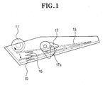
- a conventional paper tray has a pick-up roller 11 disposed in a paper tray body 10.
- a pressure plate 13 is disposed under the pick-up roller 11 and is capable of moving up and down.
- a spring is disposed between the pressure plate 13 and the bottom of the tray body 10. The resilience of the spring 15 pushes pressure plate 13 against the pick-up roller 11. Accordingly, a predetermined pick-up force is exerted on the paper on the pressure plate 13.
- the paper tray further includes a lever 17 for separating the pressure plate 13 from the pick-up roller 11 so that a stack of paper can be placed between the pressure plate 13 and the pick-up roller 11.
- the paper is stacked on the pressure plate 13 after the pressure plate 13 has been separated from the pick-up roller 11 by the rotation of the lever 17. At this time, a user is required to return the lever 17 to its original position to keep a predetermined degree of pressure between the pick-up roller 11 and the top sheet of paper. If the user inadvertently does not return the lever 17 to its original position, the paper is not smoothly withdrawn from the tray 10.
- the pressure plate 13 on which the paper is stacked is open to the outside, the paper is easily contaminated with dust and dirt.
- a paper supply apparatus is characterised by a cover, pivotably mounted to the paper tray, for protecting paper stacked on the sprung plate.
- a transmission may connect the roller to the cover so that rotation of the roller can be accompanied by the cover pivoting closed.
- the transmission comprises a freewheel mechanism and a torque-sensitive clutch.
- the freewheel mechanism and the torque-sensitive clutch form an integrated transmission element which may comprise a ratchet and pawl mechanism, the ratchet part thereof having an rounded undulating profile and the pawl part thereof being resiliently deformable to ride over the undulations of the ratchet part.
- Opening of the cover may operate a pushing member, for example a rotatable finger, which pushes the plate down.
- the apparatus may also include sheet separation means for preventing multiple sheets being withdrawn at one time.
- the sheet separation means may be lifted or pivoted by a level which is operated by the plate when the plate is pushed down.
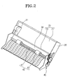
- a paper tray for a printing apparatus includes a tray body 20, a pressure plate 30 disposed in the tray body 20 and movable up and down, a pick-up roller 40 for drawing paper stacked on the pressure plate 30 from the tray 10, a spring 50 for bias the pressure plate 30 elastically towards the pick-up roller 40, a claw unit for separating the paper being drawn from the pressure plate 30 so that only one sheet is withdrawn at a time and a cover member 70 to protect the paper in the tray 10 from dust and other contaminants.
- the tray body 20 is mounted in the printing apparatus to supply the paper thereto.
- the tray body 20 is provided with a paper guide 21 capable being slid sideways to align the paper stacked in the tray body 20.
- the paper guide 21 is manually slidable back and forth in the tray body 20 parallel to the shaft 41 of the pick-up roller 40.
- the pressure plate 30 receives the paper and has one end hingedly connected to the tray body 20 and the other end elastically biased toward the pick-up roller 40 by the spring 50 such that the pressure plate 30 can move up and down .
- the spring 50 elastically biases the pressure plate 30 towards the pick-up roller 40 such that the top sheet of the paper stacked on the pressure plate 30 comes into contact with the pick-up roller 40 with a predetermined pressure. Accordingly, there is a predetermined friction between the paper and the pick-up roller 40. The predetermined friction allows the paper to be withdrawn when the pick-up roller 40 rotates.
- the pick-up roller 40 has a shaft 41, the ends of which are held in respective side walls of the tray body 20 and a plurality of spaced roller bodies 43 disposed on the shaft 41.
- the roller bodies 43 are made of a rubber as used in for the rollers of known paper trays.
- the shaft 41 is rotated by a motor in the printing apparatus's body (not shown) via a transmission 45.
- the claw unit is provided to separate the paper drawn from the pressure plate 30 so that it is removed sheet by sheet from the paper tray.
- the claw unit includes a claw lever 61 having one end pivotably connected with a sidewall of the tray body 20 and a spring 63 for elastically biasing the other end of the claw lever 61 downward, i.e. towards the pressure plate 30.
- the other end of the claw lever 61 is connected to the spring 63 and supports the front end of the paper stacked on the pressure plate 30.
- the cover member 70 protects the paper stack on the pressure plate 30 from foreign material such as dust.
- the cover member 70 includes a plate-shaped cover body 71 and a pivot shaft 73 disposed at an end of the cover body 71. The ends of the pivot shaft 73 are rotatably supported in respective sidewalls of the tray body 20.
- the user In order to stack the paper on the pressure plate 30, the user first pivots open the cover member 70. After stacking the paper on the pressure plate 30, the user closes the cover member 70 by pivoting it back to its original position.
- the paper tray further includes an associated movement unit to move the cover member 70 and the claw unit in association with each other.
- the associated movement unit includes a rotary member 75 connected to the pivot shaft 73 and a lever 77 pivotably mounted to the tray body 20.
- the rotary member 75 has an disc part 75a and a finger 75b projecting radially from the disc part 75a.
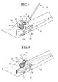
- the finger 75b rotates in direction "A" when the cover member 70 is opened and comes into contact with the pressure plate 30. Consequently, the pressure plate 30 is moved downwards by the finger 75b.
- the lever 77 is pivotably mounted to a sidewall of the tray body 20.
- the second pivot lever 77 has a first arm 77a and a second arm 77b that are different from each other in length.
- the first arm 77a is rotated in direction "A” when the pressure plate 30 is moved downwards by rotary member 75. Rotating in direction "A”, the second arm 77b pushes the claw lever 61 upward. Then, the claw lever 61 and the pressure plate 30 are separated from each other by respectively ascending and descending.
- the paper tray further includes an automatic driving unit for automatically closing the cover member 70 to return the pressure plate 30 and the claw unit 60 to their original positions when the pickup roller 40 is driven with the cover member 70 open.
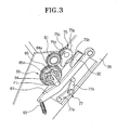
- the automatic driving unit includes gear teeth 75c formed along part of the periphery of the disc part 75a of the rotary member 75, an idler gear 81 rotatably disposed on the tray body 20 and a main gear 83 disposed at the shaft 41 of the pick-up roller 40.
- the gear teeth 75c engage with and disengage from the idler gear 81 depending on the angular position of the rotary member 75. That is, the gear teeth 75c engage the idler gear 81 when the cover member 70 is opened and disengage from the idler gear 81 when the cover member 70 is closed. Also, in an area adjacent to the gear teeth 75c is formed a slit 75d. The slit 75d ensures that the gear teeth 75c smoothly engage with and disengage from the idler gear 81.
- the idler gear 81 is interposed between the rotary member 75 and the main gear 83.
- the idler gear 81 is engaged with the main gear 83. Also, the idle gear 81 selectively engages the gear teeth 75c.
- the main gear 83 transmits drive to the cover member 70 via the idler gear 81 such that the cover member 70 is automatically closed. Also, when the idler gear 81 is subjected to a predetermined torque, the main gear 83 serves as a clutch that selectively blocks transmission of drive from the shaft 41 of the pick-up roller 40 to the idler gear 81, depending on a magnitude of the predetermined torque.
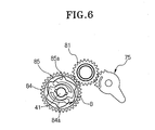
- the main gear 83 has an inner resilient pawl unit 84 fastened to the shaft 41 of the pick-up roller 40 and an outer rounded ratchet member 85. Under low torque conditions the pawl unit 84 and the rounded ratchet member 85 operate like a conventional ratchet and pawl arrangement.
- the ratchet member 85 has teeth formed on its outer circumference which engage the teeth of the idler gear 81.
- the friction between the pawl unit 84 and the ratchet member 85 means that they move together until the torque overcomes the friction and the pawl unit 84 begins to rotate relative to the ratchet member 85. Accordingly, the pawl unit 84 performs the clutch function.
- the ratchet member 85 has a profile 85a formed along an inner circumference thereof. The radius of curvature of the profile 85a repeatedly increases and decreases circumferentially.
- the pawl unit 84 has a pair of resilient arms 84a which bear against the profile 85a. The resilient arms 84a are symmetrical and their ends contact the profile 85a and generate friction. The resilient arms 84a are deflected and released while following the profile 85a.
- Printing may be started with the cover member 70 open.
- the pick-up roller 40 is rotated in the direction "B” by a driving force transmitted from the printing apparatus body.
- This rotates the pawl unit 84 of the main gear 83 in the direction "B” with the shaft 41 of the pick-up roller 40.
- the ratchet member 85 is also rotated in the direction "B”.
- the idler gear 81 engaged with the main gear 83, is rotated and rotates the rotary member 75 in the direction "B".
- the idler gear 81 is engaged with the teeth 75c of the rotary member 75 when the cover member 70 is open and, accordingly, the rotary member 75 is rotated in accordance with the rotation of the idler gear 81.
- the cover member 70 is moved in the direction "B" until it is closed.
- the idler gear 81 and the teeth 75c are disengaged from each other such that the driving force is no longer transmitted to the rotary member 75.
- the user may open the cover member 70 while the pick-up roller 40 is picking up the paper.
- the rotary member 75 is rotated in the direction "A” and the pressure plate 30 and the claw lever 61 are moved to the positions shown in Figure 4.
- the idler gear 81 is rotated in the direction "A! by the driving force transmitted from the main gear 83.
- the gear teeth 75c and the idler gear 81 are respectively subjected to loads in opposite directions, such that the idler gear 81 stops rotating in the direction "A".
- the ratchet member 85 engaged with the idler gear 81, also stops rotating. Then, as shown in Figure 6, the resilient arms 84a of the pawl unit 84 are deformed, i.e. deflected, and released such that only the pawl unit 84 rotates with the rotary shaft 41 in the direction "B". That is, the resilient arms 84a overcome the friction between them and the profile 85a of the ratchet member 85 and moves in an out of the undulations of the profile 85a repeatedly.
- the cover member 70 is automatically closed. Also, the stability of the product can be achieved by preventing the deformation of the cover member 70 and the damage to the internal parts when the cover member 71 is forcibly opened.
- the paper tray of the printing apparatus as described above prevents the paper from being contaminated with foreign material such as dust due to the presence of the cover member 70 to cover the paper stacked on the pressure plate 30.
- the cover member 70 when the cover member 70 is opened for paper to be loaded, the cover member 70 automatically closed by drive from the pick-up roller 40 and, accordingly, the paper can be withdrawn normally by the pick-up roller 40.
Landscapes
- Engineering & Computer Science (AREA)
- Mechanical Engineering (AREA)
- Sheets, Magazines, And Separation Thereof (AREA)
Abstract
Description
Claims (24)
- A paper supply apparatus for a printing apparatus, the paper supply apparatus comprising:characterised by a cover (70), pivotably mounted to the paper tray (20), for protecting paper stacked on the sprung plate (30).a paper tray (20);a roller (43) for withdrawing sheets of paper from the paper tray (20); anda sprung plate (30) mounted to the paper tray (20) for pressing the top sheet of a stack of paper, supported thereon, against the roller (43),
- A paper supply apparatus according to claim 1, including a transmission (75, 81, 83) connecting the roller (43) to the cover (70), whereby rotation of the roller (43) can be accompanied by the cover (70) pivoting closed.
- A paper supply apparatus according to claim 2, wherein the transmission (75, 81, 83) comprises a freewheel mechanism and a torque-sensitive clutch.
- A paper supply apparatus according to claim 3, wherein the freewheel mechanism and the torque-sensitive clutch form an integrated transmission element (84, 85).
- A paper supply apparatus 4, wherein the integrated transmission element (84, 85) comprises a ratchet and pawl mechanism, the ratchet part (85) thereof having an rounded undulating profile (85a) and the pawl part (84a) thereof being resiliently deformable to ride over the undulations of the ratchet part (85).
- A paper cartridge for a printing apparatus to print on paper, comprising:a cartridge body;a pressure plate to move upward and downward in the cartridge body, the paper being stacked thereon;a pick-up roller to pick up the paper stacked on the pressure plate;a spring to elastically bias the pressure plate toward the pick-up roller;a claw unit to support a front end of the paper stacked on the pressure plate and to separate the paper picked up by the pick-up roller sheet by sheet; anda cover member pivotably disposed at the cartridge body to cover the paper stacked on the pressure plate, to prevent the paper from being contaminated with a foreign material.
- The paper cartridge of claim 6, further comprising an association movement unit through which the cover member and the claw unit are moved in association with each other, the association movement unit to separate the pressure plate from the claw unit to allow the paper to be stacked on the pressure plate.
- The paper cartridge of claim 7, wherein the cover member includes a pivot shaft, and the association movement unit comprises:a first pivot lever connected to the pivot shaft of the cover member to rotate with the pivot shaft, and to move the pressure plate downward by contacting the pressure plate when the cover member is opened; anda second pivot lever pivotably disposed at the cartridge body, to rotate in contact with the downward moving pressure plate and to push the claw unit upward to thereby separate the pressure plate from the claw unit.
- The paper cartridge of claim 7, further comprising an automatic driving unit to automatically close the cover member when the pick-up roller is driven with the cover member being opened, to thereby return the pressure plate and the claw unit together.
- The paper cartridge claim 9, wherein the cover member includes a pivot shaft, and the automatic driving unit comprises:a first pivot lever disposed at the pivot shaft of the cover member and to rotate with the pivot shaft, to selectively press and move the pressure plate downward, the first pivot lever having gear teeth formed along an external circumference thereof;an idle gear rotatably disposed at the cartridge body and selectively engaged with the gear teeth of the first pivot lever depending on a rotation position of the first pivot lever; anda main gear to transmit a driving force of the pick-up roller to the idle gear.
- The paper cartridge of claim 10, wherein the main gear serves as a clutch to selectively block the driving force of the pick-up roller from being transmitted to the idle gear when a torque occurs in the idle gear to cause the idle gear to rotate in an opposite direction to a rotation direction of the pick-up roller.
- The paper cartridge of claim 11, wherein the pickup roller comprises a rotary shaft and the main gear comprises:an inner gear connected to the rotary shaft of the pick-up roller; andan outer gear connected to an outer side of the inner gear and engaged with the idle gear, wherein the inner gear and the outer gear are rotated together with each other due to a friction occurring therebetween, or only the inner gear is rotated when the outer gear is subject to a torque which is greater than the friction, thereby preventing the driving force from being transmitted to the idle gear.
- The paper cartridge of claim 12, wherein:the outer gear has a groove formed along an inner circumference thereof, a curvature radius of the groove repeatedly increasing and decreasing, andthe inner gear has a resilient member resiliently deformed by contact with the groove when the inner gear rotates, and due to a friction occurring between the resilient member and the groove, the inner gear and the outer gear are rotated with each other.
- The paper cartridge of claim 10, wherein the gear teeth of the first pivot lever are engaged with the idle gear when the cover member is opened and the gear teeth are disengaged from the idle gear when the cover member is closed.
- A paper cartridge for a printing apparatus to print on paper, comprising:a plate to move in a first and a second direction, the paper being stacked thereon;a roller to pick up the paper stacked on the plate;a cover to cover the paper stacked on the plate in a first position of the cover, the paper not being covered by the cover in a second position of the cover; anda separator to separate the paper picked up by the roller sheet by sheet,the separator being in contact with the plate in the first position of the cover andbeing separated from the plate in the second position of the cover.
- The paper cartridge of claim 15, further comprising a bias unit to bias the plate towards the roller.
- The paper cartridge of claim 15, further comprising:a pivot shaft connected to the cover; anda movement unit, comprising:a first pivot lever connected to the pivot shaft to rotate with the pivot shaft, and to move the plate in the first direction by contacting the plate when the cover is moved to the second position, anda second pivot lever to rotate in contact with the plate moving in the first direction and to push the separator in the second direction to thereby separate the plate from the separator.
- The paper cartridge of claim 15, further comprising an automatic driving unit to automatically move the cover to the first position when the roller is driven with the cover in the second position.
- The paper cartridge of claim 18, wherein the cover includes a pivot shaft, and the automatic driving unit comprises:a first pivot lever disposed at the pivot shaft of the cover and to rotate with the pivot shaft, to selectively press and move the plate in the first direction, the first pivot lever having gear teeth formed along an external circumference thereof;an idle gear rotatably selectively engaged with the gear teeth of the first pivot lever depending on a rotation position of the first pivot lever; anda main gear to transmit a driving force of the roller to the idle gear.
- The paper cartridge of claim 19, wherein the gear teeth of the first pivot lever are engaged with the idle gear when the cover is in the second position and the gear teeth are disengaged from the idle gear when the cover is in the first position.
- A paper cartridge for a printing apparatus to print on paper, comprising:a plate, the paper being stacked thereon;a roller to pick up the paper stacked on the plate;a cover to cover the paper stacked on the plate in a first position of the cover, the paper not being covered by the cover in a second position of the cover; andan automatic driving unit to automatically move the cover to the first position when the roller is driven with the cover in the second position.
- The paper cartridge claim 16, wherein the cover includes a pivot shaft, and the automatic driving unit comprises:a first pivot lever disposed at the pivot shaft of the cover and to rotate with the pivot shaft, to selectively press and move the plate in the first direction, the first pivot lever having gear teeth formed along an external circumference thereof;an idle gear rotatably selectively engaged with the gear teeth of the first pivot lever depending on a rotation position of the first pivot lever; anda main gear to transmit a driving force of the roller to the idle gear.
- The paper cartridge of claim 22, wherein the gear teeth of the first pivot lever are engaged with the idle gear when the cover is in the second position and the gear teeth are disengaged from the idle gear when the cover is in the first position.
- A printing apparatus to print on paper, comprising:a body; anda paper cartridge, disposed in the body, comprising:a plate to move in a first and a second direction, the paper being stacked thereon,a roller to pick up the paper stacked on the plate,a cover to cover the paper stacked on the plate in a first position of the cover, the paper not being covered by the cover in a second position of the cover, anda separator to separate the paper picked up by the roller sheet by sheet,the separator being in contact with the plate in the first position of the cover and being separated from the plate in the second position of the cover.
Applications Claiming Priority (2)
| Application Number | Priority Date | Filing Date | Title |
|---|---|---|---|
| KR2002025921 | 2002-05-10 | ||
| KR10-2002-0025921A KR100431006B1 (en) | 2002-05-10 | 2002-05-10 | Paper cartridge for printer |
Publications (3)
| Publication Number | Publication Date |
|---|---|
| EP1361186A2 true EP1361186A2 (en) | 2003-11-12 |
| EP1361186A3 EP1361186A3 (en) | 2004-05-26 |
| EP1361186B1 EP1361186B1 (en) | 2006-09-06 |
Family
ID=29244831
Family Applications (1)
| Application Number | Title | Priority Date | Filing Date |
|---|---|---|---|
| EP03252315A Expired - Lifetime EP1361186B1 (en) | 2002-05-10 | 2003-04-11 | Paper supply apparatus for a printing apparatus |
Country Status (6)
| Country | Link |
|---|---|
| US (1) | US6953190B2 (en) |
| EP (1) | EP1361186B1 (en) |
| JP (1) | JP3652689B2 (en) |
| KR (1) | KR100431006B1 (en) |
| CN (2) | CN100377889C (en) |
| DE (1) | DE60308087T2 (en) |
Cited By (1)
| Publication number | Priority date | Publication date | Assignee | Title |
|---|---|---|---|---|
| CN100460300C (en) * | 2004-03-02 | 2009-02-11 | 日立欧姆龙金融系统有限公司 | Paper Item Handling Device |
Families Citing this family (16)
| Publication number | Priority date | Publication date | Assignee | Title |
|---|---|---|---|---|
| JP2004083202A (en) * | 2002-08-27 | 2004-03-18 | Matsushita Electric Ind Co Ltd | Separate paper feeder |
| CN100348425C (en) * | 2004-01-20 | 2007-11-14 | 三星电子株式会社 | Media cassette for printing apparatus |
| JP2008007311A (en) * | 2006-06-30 | 2008-01-17 | Brother Ind Ltd | Image recording device |
| US7571906B2 (en) * | 2006-07-10 | 2009-08-11 | Silverbrook Research Pty Ltd | Sheet feed mechanism |
| US8033540B2 (en) | 2006-10-20 | 2011-10-11 | Samsung Electronics Co., Ltd. | Image forming apparatus having pick-up roller cover |
| JP2008114947A (en) * | 2006-11-01 | 2008-05-22 | Seiko Epson Corp | Hopper apparatus, recording apparatus, and liquid ejecting apparatus |
| JP4388111B2 (en) * | 2007-08-16 | 2009-12-24 | 株式会社沖データ | Image forming apparatus |
| JP2009286517A (en) * | 2008-05-27 | 2009-12-10 | Kyocera Mita Corp | Paper feeding device, document conveying device mounted with the same device and image forming device |
| JP5398387B2 (en) * | 2009-06-30 | 2014-01-29 | キヤノン株式会社 | Feeding device and recording device |
| KR101486327B1 (en) * | 2013-11-14 | 2015-02-06 | 프리닉스(주) | Cam for portable thermal sublimation printer |
| JP6478598B2 (en) * | 2014-12-02 | 2019-03-06 | キヤノン株式会社 | Sheet feeding apparatus and image forming apparatus |
| JP6428303B2 (en) * | 2015-01-24 | 2018-11-28 | 株式会社リコー | Paper feeding device, image forming device |
| KR20200011809A (en) * | 2018-07-25 | 2020-02-04 | 휴렛-팩커드 디벨롭먼트 컴퍼니, 엘.피. | Pickup roller rotated by driving force for moving knock-up plate |
| EP3617106B1 (en) * | 2018-08-29 | 2024-01-03 | Seiko Epson Corporation | Medium feeding apparatus, image reading apparatus, and medium feeding method |
| JP2024010587A (en) * | 2022-07-12 | 2024-01-24 | キヤノン株式会社 | Sheet feeding device or image reading device |
| JP2025017498A (en) * | 2023-07-25 | 2025-02-06 | セイコーエプソン株式会社 | Recording device |
Family Cites Families (24)
| Publication number | Priority date | Publication date | Assignee | Title |
|---|---|---|---|---|
| JPS56114957A (en) * | 1980-02-18 | 1981-09-09 | Canon Inc | Transfer material feeder |
| US4406448A (en) * | 1981-07-24 | 1983-09-27 | Pitney Bowes Inc. | Paper cassette |
| JPS5953341A (en) * | 1982-09-17 | 1984-03-28 | Ricoh Co Ltd | sheet storage container |
| JPS59105229U (en) * | 1982-12-28 | 1984-07-16 | 株式会社東芝 | Paper cassette device |
| JPS6155031A (en) | 1984-08-25 | 1986-03-19 | Mita Ind Co Ltd | Paper feeding cassette for copying machine |
| US4772007A (en) * | 1984-10-19 | 1988-09-20 | Canon Kabushiki Kaisha | Cut sheet holding and feeding apparatus |
| JPH0317066Y2 (en) * | 1986-03-31 | 1991-04-11 | ||
| US4852869A (en) * | 1987-07-31 | 1989-08-01 | Kabushiki Kaisha Toshiba | Feed apparatus capable of feeding image forming media by relatively small drive power |
| JPH04117841U (en) * | 1991-04-03 | 1992-10-21 | 株式会社リコー | Paper cassette |
| JP3227256B2 (en) * | 1993-03-16 | 2001-11-12 | 理想科学工業株式会社 | Paper feeder of image forming device |
| JP2804425B2 (en) | 1993-06-30 | 1998-09-24 | ダイキョー・ベバスト株式会社 | Guide rail structure of sunroof equipment |
| JP3350194B2 (en) * | 1993-12-20 | 2002-11-25 | 株式会社リコー | Paper feeder |
| JPH07267390A (en) | 1994-03-25 | 1995-10-17 | Ricoh Co Ltd | Paper feeder and facsimile machine |
| JPH07277534A (en) * | 1994-04-13 | 1995-10-24 | Ricoh Co Ltd | Paper cassette |
| JP3263268B2 (en) * | 1995-02-01 | 2002-03-04 | 株式会社リコー | Paper feeder |
| JPH08239130A (en) * | 1995-03-06 | 1996-09-17 | Mita Ind Co Ltd | Image forming device |
| JP3726358B2 (en) | 1996-07-01 | 2005-12-14 | ブラザー工業株式会社 | Paper transport device |
| JPH1059555A (en) | 1996-08-19 | 1998-03-03 | Brother Ind Ltd | Paper feeder and printer |
| JP3750124B2 (en) * | 1996-08-22 | 2006-03-01 | ブラザー工業株式会社 | Paper feeding device and printing device |
| KR200334915Y1 (en) * | 1999-03-13 | 2003-12-06 | 주식회사신도리코 | Feeding system moving both bottom plate and corner separator when insert recording paper to cassette |
| JP2001206572A (en) * | 2000-01-28 | 2001-07-31 | Toshiba Tec Corp | Paper feed cassette separation claw |
| US6523821B2 (en) * | 2000-02-23 | 2003-02-25 | Kyocera Mita Corporation | Paper feeder apparatus for use with image forming apparatus |
| JP2002326724A (en) | 2001-04-27 | 2002-11-12 | Sharp Corp | Recording paper feeder |
| KR100412497B1 (en) * | 2001-11-12 | 2003-12-31 | 삼성전자주식회사 | Paper cassette for printer |
-
2002
- 2002-05-10 KR KR10-2002-0025921A patent/KR100431006B1/en not_active Expired - Fee Related
-
2003
- 2003-02-21 CN CNB2005100702240A patent/CN100377889C/en not_active Expired - Fee Related
- 2003-02-21 CN CNB031063055A patent/CN1233523C/en not_active Expired - Fee Related
- 2003-03-21 US US10/393,427 patent/US6953190B2/en not_active Expired - Fee Related
- 2003-04-11 EP EP03252315A patent/EP1361186B1/en not_active Expired - Lifetime
- 2003-04-11 DE DE60308087T patent/DE60308087T2/en not_active Expired - Fee Related
- 2003-05-09 JP JP2003131484A patent/JP3652689B2/en not_active Expired - Fee Related
Cited By (1)
| Publication number | Priority date | Publication date | Assignee | Title |
|---|---|---|---|---|
| CN100460300C (en) * | 2004-03-02 | 2009-02-11 | 日立欧姆龙金融系统有限公司 | Paper Item Handling Device |
Also Published As
| Publication number | Publication date |
|---|---|
| KR20030087841A (en) | 2003-11-15 |
| US6953190B2 (en) | 2005-10-11 |
| DE60308087T2 (en) | 2007-01-04 |
| EP1361186A3 (en) | 2004-05-26 |
| CN1680110A (en) | 2005-10-12 |
| JP2003327335A (en) | 2003-11-19 |
| DE60308087D1 (en) | 2006-10-19 |
| EP1361186B1 (en) | 2006-09-06 |
| US20030209851A1 (en) | 2003-11-13 |
| CN1456443A (en) | 2003-11-19 |
| JP3652689B2 (en) | 2005-05-25 |
| KR100431006B1 (en) | 2004-05-12 |
| CN1233523C (en) | 2005-12-28 |
| CN100377889C (en) | 2008-04-02 |
Similar Documents
| Publication | Publication Date | Title |
|---|---|---|
| EP1361186B1 (en) | Paper supply apparatus for a printing apparatus | |
| KR101139325B1 (en) | Image processing apparatus and transport device | |
| US6382619B1 (en) | Pick mechanism and image forming device including the same | |
| EP0204227A2 (en) | Paper feeding device | |
| US20030184000A1 (en) | Sheet feeding apparatus for printing device | |
| US9033332B2 (en) | Sheet conveying device with stopper | |
| JP4722740B2 (en) | Medium conveying apparatus and image forming apparatus | |
| EP0918028B1 (en) | A sheet feeding apparatus | |
| US5775686A (en) | Sheet feeding device with lifter member to hold sheets at predetermined height | |
| EP1930782A2 (en) | Image Forming Apparatus | |
| JP4773100B2 (en) | Improved paper pick roller replacement method and assembly | |
| JPH07187429A (en) | Automatic document feeder | |
| EP1439073B1 (en) | Image forming apparatus with pivotable sheet support | |
| JP5094982B2 (en) | Medium conveying apparatus and image forming apparatus | |
| US4277059A (en) | Sheet feeder for typewriters | |
| US4687192A (en) | Sheet feed apparatus with fixed separator protrusions | |
| KR100553871B1 (en) | Knock-up plate lifting device for printing equipment | |
| JP2547978B2 (en) | Sheet material feeder | |
| JP4515970B2 (en) | Paper feeder | |
| KR100514732B1 (en) | Knock-up plate lifting apparatus for printing device | |
| JPH045479Y2 (en) | ||
| JP3193201B2 (en) | Paper feeder | |
| US20060180976A1 (en) | Manual paper feeding device for image forming apparatus | |
| JPS6219336B2 (en) | ||
| JPH05330682A (en) | Paper feeder |
Legal Events
| Date | Code | Title | Description |
|---|---|---|---|
| PUAI | Public reference made under article 153(3) epc to a published international application that has entered the european phase |
Free format text: ORIGINAL CODE: 0009012 |
|
| AK | Designated contracting states |
Kind code of ref document: A2 Designated state(s): AT BE BG CH CY CZ DE DK EE ES FI FR GB GR HU IE IT LI LU MC NL PT RO SE SI SK TR |
|
| AX | Request for extension of the european patent |
Extension state: AL LT LV MK |
|
| PUAL | Search report despatched |
Free format text: ORIGINAL CODE: 0009013 |
|
| AK | Designated contracting states |
Kind code of ref document: A3 Designated state(s): AT BE BG CH CY CZ DE DK EE ES FI FR GB GR HU IE IT LI LU MC NL PT RO SE SI SK TR |
|
| AX | Request for extension of the european patent |
Extension state: AL LT LV MK |
|
| 17P | Request for examination filed |
Effective date: 20040629 |
|
| RAP1 | Party data changed (applicant data changed or rights of an application transferred) |
Owner name: SAMSUNG ELECTRONICS CO., LTD. |
|
| 17Q | First examination report despatched |
Effective date: 20041022 |
|
| AKX | Designation fees paid |
Designated state(s): DE FR GB NL |
|
| GRAP | Despatch of communication of intention to grant a patent |
Free format text: ORIGINAL CODE: EPIDOSNIGR1 |
|
| GRAS | Grant fee paid |
Free format text: ORIGINAL CODE: EPIDOSNIGR3 |
|
| GRAA | (expected) grant |
Free format text: ORIGINAL CODE: 0009210 |
|
| AK | Designated contracting states |
Kind code of ref document: B1 Designated state(s): DE FR GB NL |
|
| REG | Reference to a national code |
Ref country code: GB Ref legal event code: FG4D |
|
| REF | Corresponds to: |
Ref document number: 60308087 Country of ref document: DE Date of ref document: 20061019 Kind code of ref document: P |
|
| ET | Fr: translation filed | ||
| PLBE | No opposition filed within time limit |
Free format text: ORIGINAL CODE: 0009261 |
|
| STAA | Information on the status of an ep patent application or granted ep patent |
Free format text: STATUS: NO OPPOSITION FILED WITHIN TIME LIMIT |
|
| 26N | No opposition filed |
Effective date: 20070607 |
|
| PGFP | Annual fee paid to national office [announced via postgrant information from national office to epo] |
Ref country code: DE Payment date: 20080417 Year of fee payment: 6 Ref country code: FR Payment date: 20080312 Year of fee payment: 6 |
|
| PGFP | Annual fee paid to national office [announced via postgrant information from national office to epo] |
Ref country code: NL Payment date: 20080403 Year of fee payment: 6 |
|
| PGFP | Annual fee paid to national office [announced via postgrant information from national office to epo] |
Ref country code: GB Payment date: 20080416 Year of fee payment: 6 |
|
| GBPC | Gb: european patent ceased through non-payment of renewal fee |
Effective date: 20090411 |
|
| NLV4 | Nl: lapsed or anulled due to non-payment of the annual fee |
Effective date: 20091101 |
|
| REG | Reference to a national code |
Ref country code: FR Ref legal event code: ST Effective date: 20091231 |
|
| PG25 | Lapsed in a contracting state [announced via postgrant information from national office to epo] |
Ref country code: DE Free format text: LAPSE BECAUSE OF NON-PAYMENT OF DUE FEES Effective date: 20091103 |
|
| PG25 | Lapsed in a contracting state [announced via postgrant information from national office to epo] |
Ref country code: NL Free format text: LAPSE BECAUSE OF NON-PAYMENT OF DUE FEES Effective date: 20091101 |
|
| PG25 | Lapsed in a contracting state [announced via postgrant information from national office to epo] |
Ref country code: FR Free format text: LAPSE BECAUSE OF NON-PAYMENT OF DUE FEES Effective date: 20091222 Ref country code: GB Free format text: LAPSE BECAUSE OF NON-PAYMENT OF DUE FEES Effective date: 20090411 |
|
| REG | Reference to a national code |
Ref country code: GB Ref legal event code: 732E Free format text: REGISTERED BETWEEN 20170406 AND 20170412 |
|
| REG | Reference to a national code |
Ref country code: FR Ref legal event code: TP Owner name: S-PRINTING SOLUTION CO., LTD., KR Effective date: 20170912 |