EP1360922A2 - Aspirateur robotic avec tête de nettoyage amovible et mappage semi-automatique de l'environnement - Google Patents
Aspirateur robotic avec tête de nettoyage amovible et mappage semi-automatique de l'environnement Download PDFInfo
- Publication number
- EP1360922A2 EP1360922A2 EP03010312A EP03010312A EP1360922A2 EP 1360922 A2 EP1360922 A2 EP 1360922A2 EP 03010312 A EP03010312 A EP 03010312A EP 03010312 A EP03010312 A EP 03010312A EP 1360922 A2 EP1360922 A2 EP 1360922A2
- Authority
- EP
- European Patent Office
- Prior art keywords
- vacuum
- controller
- power
- cleaning head
- set forth
- Prior art date
- Legal status (The legal status is an assumption and is not a legal conclusion. Google has not performed a legal analysis and makes no representation as to the accuracy of the status listed.)
- Granted
Links
- 238000013507 mapping Methods 0.000 title claims abstract description 18
- 238000004140 cleaning Methods 0.000 claims abstract description 158
- 238000004891 communication Methods 0.000 claims description 54
- 238000009826 distribution Methods 0.000 claims description 31
- 230000006870 function Effects 0.000 claims description 21
- 230000007246 mechanism Effects 0.000 claims description 21
- 230000004807 localization Effects 0.000 claims description 18
- 239000000428 dust Substances 0.000 claims description 9
- 239000002245 particle Substances 0.000 claims description 5
- 238000000034 method Methods 0.000 abstract description 7
- 238000010586 diagram Methods 0.000 description 9
- 238000005516 engineering process Methods 0.000 description 5
- 230000008901 benefit Effects 0.000 description 4
- 239000003570 air Substances 0.000 description 3
- 238000007664 blowing Methods 0.000 description 3
- 238000006243 chemical reaction Methods 0.000 description 3
- 230000003750 conditioning effect Effects 0.000 description 3
- 239000000446 fuel Substances 0.000 description 3
- 230000009471 action Effects 0.000 description 2
- 239000000463 material Substances 0.000 description 2
- 238000012986 modification Methods 0.000 description 2
- 230000004048 modification Effects 0.000 description 2
- 230000003287 optical effect Effects 0.000 description 2
- 238000010407 vacuum cleaning Methods 0.000 description 2
- 238000004804 winding Methods 0.000 description 2
- 229910000639 Spring steel Inorganic materials 0.000 description 1
- 230000004913 activation Effects 0.000 description 1
- 239000012080 ambient air Substances 0.000 description 1
- 238000013459 approach Methods 0.000 description 1
- 238000009530 blood pressure measurement Methods 0.000 description 1
- 239000000470 constituent Substances 0.000 description 1
- 238000001514 detection method Methods 0.000 description 1
- 238000006073 displacement reaction Methods 0.000 description 1
- 230000000694 effects Effects 0.000 description 1
- 239000000835 fiber Substances 0.000 description 1
- 238000004519 manufacturing process Methods 0.000 description 1
- 238000012545 processing Methods 0.000 description 1
- 230000003252 repetitive effect Effects 0.000 description 1
- 230000000717 retained effect Effects 0.000 description 1
- 238000007665 sagging Methods 0.000 description 1
- 238000009987 spinning Methods 0.000 description 1
- 239000002436 steel type Substances 0.000 description 1
Images


Classifications
-
- A—HUMAN NECESSITIES
- A47—FURNITURE; DOMESTIC ARTICLES OR APPLIANCES; COFFEE MILLS; SPICE MILLS; SUCTION CLEANERS IN GENERAL
- A47L—DOMESTIC WASHING OR CLEANING; SUCTION CLEANERS IN GENERAL
- A47L9/00—Details or accessories of suction cleaners, e.g. mechanical means for controlling the suction or for effecting pulsating action; Storing devices specially adapted to suction cleaners or parts thereof; Carrying-vehicles specially adapted for suction cleaners
- A47L9/02—Nozzles
- A47L9/04—Nozzles with driven brushes or agitators
- A47L9/0405—Driving means for the brushes or agitators
- A47L9/0411—Driving means for the brushes or agitators driven by electric motor
-
- A—HUMAN NECESSITIES
- A47—FURNITURE; DOMESTIC ARTICLES OR APPLIANCES; COFFEE MILLS; SPICE MILLS; SUCTION CLEANERS IN GENERAL
- A47L—DOMESTIC WASHING OR CLEANING; SUCTION CLEANERS IN GENERAL
- A47L5/00—Structural features of suction cleaners
- A47L5/12—Structural features of suction cleaners with power-driven air-pumps or air-compressors, e.g. driven by motor vehicle engine vacuum
- A47L5/22—Structural features of suction cleaners with power-driven air-pumps or air-compressors, e.g. driven by motor vehicle engine vacuum with rotary fans
- A47L5/36—Suction cleaners with hose between nozzle and casing; Suction cleaners for fixing on staircases; Suction cleaners for carrying on the back
-
- A—HUMAN NECESSITIES
- A47—FURNITURE; DOMESTIC ARTICLES OR APPLIANCES; COFFEE MILLS; SPICE MILLS; SUCTION CLEANERS IN GENERAL
- A47L—DOMESTIC WASHING OR CLEANING; SUCTION CLEANERS IN GENERAL
- A47L9/00—Details or accessories of suction cleaners, e.g. mechanical means for controlling the suction or for effecting pulsating action; Storing devices specially adapted to suction cleaners or parts thereof; Carrying-vehicles specially adapted for suction cleaners
- A47L9/009—Carrying-vehicles; Arrangements of trollies or wheels; Means for avoiding mechanical obstacles
-
- A—HUMAN NECESSITIES
- A47—FURNITURE; DOMESTIC ARTICLES OR APPLIANCES; COFFEE MILLS; SPICE MILLS; SUCTION CLEANERS IN GENERAL
- A47L—DOMESTIC WASHING OR CLEANING; SUCTION CLEANERS IN GENERAL
- A47L9/00—Details or accessories of suction cleaners, e.g. mechanical means for controlling the suction or for effecting pulsating action; Storing devices specially adapted to suction cleaners or parts thereof; Carrying-vehicles specially adapted for suction cleaners
- A47L9/24—Hoses or pipes; Hose or pipe couplings
- A47L9/248—Parts, details or accessories of hoses or pipes
-
- A—HUMAN NECESSITIES
- A47—FURNITURE; DOMESTIC ARTICLES OR APPLIANCES; COFFEE MILLS; SPICE MILLS; SUCTION CLEANERS IN GENERAL
- A47L—DOMESTIC WASHING OR CLEANING; SUCTION CLEANERS IN GENERAL
- A47L9/00—Details or accessories of suction cleaners, e.g. mechanical means for controlling the suction or for effecting pulsating action; Storing devices specially adapted to suction cleaners or parts thereof; Carrying-vehicles specially adapted for suction cleaners
- A47L9/28—Installation of the electric equipment, e.g. adaptation or attachment to the suction cleaner; Controlling suction cleaners by electric means
- A47L9/2805—Parameters or conditions being sensed
- A47L9/2826—Parameters or conditions being sensed the condition of the floor
-
- A—HUMAN NECESSITIES
- A47—FURNITURE; DOMESTIC ARTICLES OR APPLIANCES; COFFEE MILLS; SPICE MILLS; SUCTION CLEANERS IN GENERAL
- A47L—DOMESTIC WASHING OR CLEANING; SUCTION CLEANERS IN GENERAL
- A47L9/00—Details or accessories of suction cleaners, e.g. mechanical means for controlling the suction or for effecting pulsating action; Storing devices specially adapted to suction cleaners or parts thereof; Carrying-vehicles specially adapted for suction cleaners
- A47L9/28—Installation of the electric equipment, e.g. adaptation or attachment to the suction cleaner; Controlling suction cleaners by electric means
- A47L9/2805—Parameters or conditions being sensed
- A47L9/2831—Motor parameters, e.g. motor load or speed
-
- A—HUMAN NECESSITIES
- A47—FURNITURE; DOMESTIC ARTICLES OR APPLIANCES; COFFEE MILLS; SPICE MILLS; SUCTION CLEANERS IN GENERAL
- A47L—DOMESTIC WASHING OR CLEANING; SUCTION CLEANERS IN GENERAL
- A47L9/00—Details or accessories of suction cleaners, e.g. mechanical means for controlling the suction or for effecting pulsating action; Storing devices specially adapted to suction cleaners or parts thereof; Carrying-vehicles specially adapted for suction cleaners
- A47L9/28—Installation of the electric equipment, e.g. adaptation or attachment to the suction cleaner; Controlling suction cleaners by electric means
- A47L9/2836—Installation of the electric equipment, e.g. adaptation or attachment to the suction cleaner; Controlling suction cleaners by electric means characterised by the parts which are controlled
- A47L9/2847—Surface treating elements
-
- A—HUMAN NECESSITIES
- A47—FURNITURE; DOMESTIC ARTICLES OR APPLIANCES; COFFEE MILLS; SPICE MILLS; SUCTION CLEANERS IN GENERAL
- A47L—DOMESTIC WASHING OR CLEANING; SUCTION CLEANERS IN GENERAL
- A47L9/00—Details or accessories of suction cleaners, e.g. mechanical means for controlling the suction or for effecting pulsating action; Storing devices specially adapted to suction cleaners or parts thereof; Carrying-vehicles specially adapted for suction cleaners
- A47L9/28—Installation of the electric equipment, e.g. adaptation or attachment to the suction cleaner; Controlling suction cleaners by electric means
- A47L9/2836—Installation of the electric equipment, e.g. adaptation or attachment to the suction cleaner; Controlling suction cleaners by electric means characterised by the parts which are controlled
- A47L9/2852—Elements for displacement of the vacuum cleaner or the accessories therefor, e.g. wheels, casters or nozzles
-
- A—HUMAN NECESSITIES
- A47—FURNITURE; DOMESTIC ARTICLES OR APPLIANCES; COFFEE MILLS; SPICE MILLS; SUCTION CLEANERS IN GENERAL
- A47L—DOMESTIC WASHING OR CLEANING; SUCTION CLEANERS IN GENERAL
- A47L9/00—Details or accessories of suction cleaners, e.g. mechanical means for controlling the suction or for effecting pulsating action; Storing devices specially adapted to suction cleaners or parts thereof; Carrying-vehicles specially adapted for suction cleaners
- A47L9/28—Installation of the electric equipment, e.g. adaptation or attachment to the suction cleaner; Controlling suction cleaners by electric means
- A47L9/2857—User input or output elements for control, e.g. buttons, switches or displays
-
- A—HUMAN NECESSITIES
- A47—FURNITURE; DOMESTIC ARTICLES OR APPLIANCES; COFFEE MILLS; SPICE MILLS; SUCTION CLEANERS IN GENERAL
- A47L—DOMESTIC WASHING OR CLEANING; SUCTION CLEANERS IN GENERAL
- A47L9/00—Details or accessories of suction cleaners, e.g. mechanical means for controlling the suction or for effecting pulsating action; Storing devices specially adapted to suction cleaners or parts thereof; Carrying-vehicles specially adapted for suction cleaners
- A47L9/28—Installation of the electric equipment, e.g. adaptation or attachment to the suction cleaner; Controlling suction cleaners by electric means
- A47L9/2889—Safety or protection devices or systems, e.g. for prevention of motor over-heating or for protection of the user
-
- A—HUMAN NECESSITIES
- A47—FURNITURE; DOMESTIC ARTICLES OR APPLIANCES; COFFEE MILLS; SPICE MILLS; SUCTION CLEANERS IN GENERAL
- A47L—DOMESTIC WASHING OR CLEANING; SUCTION CLEANERS IN GENERAL
- A47L9/00—Details or accessories of suction cleaners, e.g. mechanical means for controlling the suction or for effecting pulsating action; Storing devices specially adapted to suction cleaners or parts thereof; Carrying-vehicles specially adapted for suction cleaners
- A47L9/28—Installation of the electric equipment, e.g. adaptation or attachment to the suction cleaner; Controlling suction cleaners by electric means
- A47L9/2894—Details related to signal transmission in suction cleaners
-
- G—PHYSICS
- G05—CONTROLLING; REGULATING
- G05D—SYSTEMS FOR CONTROLLING OR REGULATING NON-ELECTRIC VARIABLES
- G05D1/00—Control of position, course or altitude of land, water, air, or space vehicles, e.g. automatic pilot
- G05D1/02—Control of position or course in two dimensions
- G05D1/021—Control of position or course in two dimensions specially adapted to land vehicles
- G05D1/0268—Control of position or course in two dimensions specially adapted to land vehicles using internal positioning means
- G05D1/0274—Control of position or course in two dimensions specially adapted to land vehicles using internal positioning means using mapping information stored in a memory device
-
- A—HUMAN NECESSITIES
- A47—FURNITURE; DOMESTIC ARTICLES OR APPLIANCES; COFFEE MILLS; SPICE MILLS; SUCTION CLEANERS IN GENERAL
- A47L—DOMESTIC WASHING OR CLEANING; SUCTION CLEANERS IN GENERAL
- A47L2201/00—Robotic cleaning machines, i.e. with automatic control of the travelling movement or the cleaning operation
- A47L2201/04—Automatic control of the travelling movement; Automatic obstacle detection
Definitions
- the invention relates to a robotic vacuum. It finds particular application in conjunction with a robotic vacuum having a controller with a removable portable vacuum, a cleaning head, and an interconnecting hose assembly and will be described with particular reference thereto.
- the robotic vacuum cleaner has an internal power source and is autonomously self-propelled.
- the robotic vacuum cleaner is also self-propelled, but uses standard utility power.
- the robotic vacuum cleaner includes a remote control and provides semi-automated environment mapping.
- the invention is also amenable to other applications.
- robots and robot technology can automate routine household tasks eliminating the need for humans to perform these repetitive and time-consuming tasks.
- technology and innovation are both limiting factors in the capability of household cleaning robots.
- Computer processing power, battery life, electronic sensors such as cameras, and efficient electric motors are all either just becoming available, cost effective, or reliable enough to use in autonomous consumer robots.
- Robotic vacuum cleaners have mounted the suction mechanics on a pivoting or transverse sliding arm so as to increase the reach of the robot. Many robotic vacuums include methods for detecting and avoiding obstacles.
- U.S. Patent No. 6,226,830 to Hendriks et al. and assigned to Philips Electronics discloses a canister-type vacuum cleaner with a self-propelled canister.
- the vacuum cleaner also includes a conventional cleaning head and a hose assembly connecting the cleaning head to the canister.
- the canister includes an electric motor, a caster wheel, two drive wheels, a controller, and at least one touch or proximity sensor.
- the controller controls at least the direction of at least one of the drive wheels.
- the sensors in the canister detect obstacles and the controller controls the canister to avoid the obstacles.
- U.S. Patent No. 6,370,453 to Sommer discloses an autonomous service robot for automatic suction of dust from floor surfaces.
- the robot is controlled so as to explore the adjacent area and to detect potential obstacles using special sensors before storing them in a data field.
- the displacement towards a new location is then carried out using the stored data until the whole accessible surface has been covered.
- One of the main constituent members of the robot includes an extensible arm that rests on the robot and on which contact and range sensors are arranged.
- airflow is forced into the robot arm.
- one or more circular rotary brushes are provided at the front end of the arm, the cleaning effect is enhanced.
- U.S. Patent No. 6,463,368 to Feiten et al. discloses a self-propelled vacuum cleaner.
- the vacuum cleaner includes a pivotable arm and a cable to connect to an electrical receptacle for power.
- the arm includes a plurality of tactile sensors to recognize obstacles by touching the obstacle with the arm.
- the vacuum cleaner also includes a processor and a memory connected via a bus. An identified and traversed path is stored in an electronic map in the memory. Every obstacle identified on the path is entered in the map.
- the vacuum cleaner includes a cable drum for winding up the cable.
- the cable drum includes a motor to drive the cable drum for unwinding or winding the cable.
- the vacuum cleaner also includes a steering mechanism, wheels, and a motor for driving the vacuum cleaner along the path.
- the canister vacuum cleaner includes a cleaning head module, a vacuum fan module (i.e., canister), and a hose assembly connecting the cleaning head module with the vacuum fan module.
- the vacuum fan module includes a controller that performs navigation and control functions for both the vacuum fan module and the cleaning head module. Alternatively, the controller may be separated from the vacuum fan module and the cleaning head module, and can be mobile.
- the vacuum fan module and the cleaning head module each include a drive mechanism for propulsion.
- the cleaning head module includes a cleaning brush assembly that can be motorized or air driven.
- the cleaning head module may also include a microcontroller that communicates with the controller.
- the invention contemplates a robotic canister-like vacuum cleaner that overcomes at least one of the above-mentioned problems and others.
- an autonomous robotic vacuum includes a self-propelled controller with a vacuum source, a dirt receptacle, a controller processor, and a power source, a self-propelled cleaning head with a suction inlet and a cleaning processor, and an interconnecting hose.
- the controller and cleaning head cooperatively traverse a surface area in tandem when the interconnecting hose is connected between the cleaning head and the controller.
- a self-propelled robotic vacuum includes a self-propelled controller with a vacuum source, a dirt receptacle, a controller processor, a power cord dispense/retract assembly, and a power distribution, a self-propelled cleaning head with a suction inlet and a cleaning processor, and an interconnecting hose.
- the controller and cleaning head cooperatively traverse a surface area in tandem when the interconnecting hose is connected between the cleaning head and the controller.
- a method of semi-automated environment mapping for a self-propelled robotic vacuum includes a self-propelled controller, a self-propelled cleaning head, a hose, and a remote control.
- the controller and cleaning head cooperatively traverse a surface area in tandem when the hose is connected between the cleaning head and the controller.
- the method includes: a) driving the robotic vacuum across a surface area of an environment to be mapped using the remote control, b) detecting characteristics of the environment, including existing obstacles, using localization sensors, c) mapping the environment from the detected characteristics and storing an environment map in a controller processor, and d) determining a route for the robotic vacuum to traverse in order to clean the surface area based on the environment map.
- FIG. 1 is a functional block diagram of an embodiment of a robotic canister-like vacuum cleaner.
- FIG. 2 is a functional block diagram showing a suction airflow path in an embodiment of a robotic canister-like vacuum cleaner.
- FIG. 3 is a functional block diagram of an embodiment of a controller associated with a robotic canister-like vacuum cleaner.
- FIG. 4 is a functional block diagram of an embodiment of a cleaning head associated with a robotic canister-like vacuum cleaner.
- FIG. 5 is a functional block diagram of another embodiment of a controller associated with a robotic canister-like vacuum cleaner.
- FIG. 6 is a functional block diagram of yet another embodiment of a controller associated with a robotic canister-like vacuum cleaner.
- FIG. 7 is a functional block diagram of still yet another embodiment of a controller associated with a robotic canister-like vacuum cleaner.
- FIG. 8 is a functional block diagram of an embodiment of a cleaning head associated with the controller of FIG. 7.
- FIG. 9 is a stylized drawing of an embodiment of a robotic canister-like vacuum cleaner.
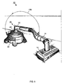
- FIG. 10 is a stylized drawing of an embodiment of a controller associated with a robotic canister-like vacuum cleaner with a hose attached.
- FIG. 11 is a stylized drawing of another embodiment of a controller associated with a robotic canister-like vacuum cleaner.
- FIG. 12 is a stylized drawing of an embodiment of a controller of a robotic canister-like vacuum cleaner with a portable vacuum removed from an associated transport module.
- an embodiment of a robotic vacuum 10 includes a controller 12, a cleaning head 14 and hose 16.
- the robotic vacuum 10 may also include an optional remote control 18.
- the controller 12 includes a portable vacuum 20 and a transport module 22.
- the robotic vacuum 10 resembles a conventional canister vacuum and may be referred to as a robotic canister-like vacuum.
- the portable vacuum 20 is selectively received (i.e., removably secured) and carried by the transport module 22 and in fluidic communication with the cleaning head 14 via the hose 16.
- the remote control 18 is in operative communication with the controller 12 and the controller is in operative communication with the cleaning head 14.
- the controller 12 and the cleaning head 14 cooperate by moving in tandem across a surface area to vacuum dirt and dust from the surface during robotic operations.
- the cleaning head 14 acts as a slave to the controller 12 for robotic operations. Since the cleaning head 14 is separate from the controller 12 in a tandem configuration, the cleaning head 14 is significantly smaller than the controller 12 and other one-piece robotic vacuums.
- the small cleaning head 14 can access and clean small or tight areas, including under and around furniture.
- the portable vacuum 20 may be removed from the transport module 22 for use as a vacuum or blower for manual operations.
- the controller 12 performs mapping localization, planning and control for the robotic vacuum 10.
- the remote control 18 allows a user to "drive” the robotic vacuum throughout the surface area. While the user is performing this function, the controller 12 is learning and mapping a floor plan for the surface area including any existing stationary objects. This includes: i) detecting characteristics of the environment, including existing obstacles, using localization sensors 78 (FIG. 3), ii) mapping the environment from the detected characteristics and storing an environment map in a controller processor 74 (FIG. 3), iii) determining a route for the robotic vacuum 10 to traverse in order to clean the surface area based on the environment map, and iv) storing the route for future reference during subsequent robotic operations.
- the optional remote control 18 provides the robotic vacuum 10 with a semi-automated environment-mapping mode. Semi-automated environment mapping allows the vacuuming function to be performed automatically in future uses based on the mapped environment stored in the controller 12.
- the cleaning head 14 includes a suction inlet 24, a brush chamber 26, a suction conduit 28 and a cleaning head outlet 29.
- the portable vacuum 20 includes a vacuum inlet 30, a dirt receptacle 32, a primary filter 34, a blower motor 36, a blower 38, a vacuum outlet 40 and a secondary filter 42.
- the blower motor 36 and the blower 38 are operatively connected when the blower motor 36 is operated.
- the blower 38 creates an airflow path by blowing air through the vacuum outlet 40. Air is drawn into the airflow path at the suction inlet 24.
- the dirt receptacle 32 may be dirt cup or canister or a disposable bag, depending on whether a bag-less or bag configuration is implemented.
- the transport module 22 includes an antenna 44, a wheel 46 and a caster 48.
- the cleaning head 14 also includes a wheel 50, a caster 52 and a brush 54.
- the transport module 22 and the cleaning head 14 both include two wheels and one or two casters.
- additional wheels, and/or additional casters are envisioned.
- tracked wheels are envisioned in addition to or in place of the wheels and casters.
- the wheels are driven to provide self-propelled movement. If the wheels (e.g., 46) are independently controlled, they may also provide steering. Otherwise, one or more of the casters (e.g., 48) may be controlled to provide steering.
- the configuration of wheel and casters in the cleaning head 14 may be the same or different from the configuration in the transport module 22. Likewise, movement and steering functions in the cleaning head 14 may be controlled in the same or different manner as movement and steering functions in the transport module 22. For vacuuming, depending on the floor type, the brush 54 rotates and assists in collection of dirt and dust particles.
- a block diagram of the controller 12 shows additional components within the portable vacuum 20 and the transport module 22.
- the portable vacuum 20 includes the blower motor 36, blower 38, a power source 56, a power distribution 58, a vacuum processor 60, a manual vacuum control 62, a hose connector 64 and a connector 66.
- the power source 56 provides electrical power to both the portable vacuum 20 and the transport module 22.
- the power source 56 may be a battery, a fuel cell, or a similar suitable source of power.
- the power source 56 provides power to power distribution 58.
- Power distribution 58 distributes power to other components within the portable vacuum 20, for example, vacuum processor 60.
- Power distribution 58 distributes power to the transport module 22 via connector 66.
- Power distribution 58 may be a terminal strip, discreet wiring, or any suitable combination of components that conduct electrical power to the proper components. For example, if any components within the portable vacuum 20 and/or transport module 22 require a voltage, frequency, or phase that is different than that provided by the power source 56, power distribution 58 may include power regulation, conditioning, and/or conversion circuitry suitable to provide the required voltage(s). In another embodiment, the power source 56 also provides power to the cleaning module 14 (FIG. 4) with power distribution 58 distributing power to the cleaning head via hose connector 64.
- the vacuum processor 60 is in communication with the manual vacuum control 62 and the blower motor 36 and controls vacuuming functions within the portable vacuum 20.
- the manual vacuum control 62 for example, includes a power switch and a power indicator light.
- the power indicator light may indicate that power has been switched on and/or the power level of the power source 56.
- the vacuum processor 60 is not required and merely replaced by discrete wiring.
- the portable vacuum 20 is removably secured to the transport module 22 during robotic vacuum cleaning operations. For manual vacuum cleaning operations, the portable vacuum 20 is removed from the transport module 22 and an accessory hose is attached to vacuum inlet 30 (FIG. 2). For manual operations, the portable vacuum 20 functions much like a shop vac or a portable canister vacuum.
- the transport module 22 includes the antenna 44, wheel 46, caster 48, a power distribution 70, a connector 72, a controller processor 74, a receiver 76, a localization sensor 78, a transport processor 82, a steering mechanism 84, a drive motor 85 and an encoder 86.
- Power distribution 70 receives power from the portable vacuum 20 via connector 72. Power is further distributed from power distribution 70 to other components within the transport module 22 including the controller processor 74 and the transport processor 82. Power distribution 70 may be a terminal strip, discreet wiring, or any suitable combination of components that conduct electrical power to the proper components. For example, if any components within the transport module 22 require a voltage, frequency, or phase that is different than that provided by the power source 56, power distribution 70 may include power regulation, conditioning, and/or conversion circuitry suitable to provide the required voltage(s).
- a controller processor 74 is in communication with the receiver 76 and the localization sensor 78.
- the remote control 18 (FIG. 1) transmits driving and other instructions to the controller 12 via the antenna 44.
- the antenna 44 communicates the instructions to the receiver 76, the receiver 76 in turn communicates the instructions to the controller processor 74.
- the controller processor 74 provides overall control functions for the robotic vacuum 10 (FIG. 1) including mapping, localization, planning and control functions.
- the controller processor 74 is in communication with the transport processor 82, the vacuum processor 60 and a cleaning processor 90 (FIG. 4) and coordinates overall operation of the robotic vacuum 10 through the various processors.
- the localization sensor 78 includes a pair of digital cameras to provide stereo optical sensing.
- the localization sensor may include any combination of optical, sonar, lidar, infrared, touch and any other suitable type of sensors.
- An environment and surface area to be cleaned may be mapped in a semi-automated mode using the remote control 18 or in an automated mode using the localization sensor 78.
- the transport processor 82 controls drive functions for the controller 12.
- the transport processor 82 is in communication with the steering mechanism 84, the drive motor 85 and the encoder 86.
- the steering mechanism 84 moves the caster 48 to steer the controller 12.
- the drive motor 85 is in operative communication with the wheel 46 to turn the wheel forward or backward to propel the controller 12.
- the encoder 86 is disposed to detect movement of the wheel 46 and provides feedback of wheel movement (e.g., slippage) to the transport processor 82.
- the drive motor 85 simultaneously controls two wheels 46 and the steering mechanism 84 controls the caster 48.
- the encoder 86 detects movement of the wheels and provides feedback indicating movement to the transport processor 82.
- the encoder 86 may also detect wheel spinning to facilitate localization.
- the steering mechanism 84 controls may control both casters independently or by a linkage between the casters or the additional caster may be free moving (i.e., freely turning about a vertical axis). If the transport module 22 includes additional casters, they may be free moving or linked to the steered caster(s).
- the transport module 22 includes two independent drive motors 85 and independently controls the two wheels 46 to provide both movement and steering functions. In this embodiment, each independently controlled drive motor 85/wheel 46 combination provides forward and backward movement.
- the transport processor 82 controls steering by driving the drive motor 85/wheel 46 combinations in different directions and/or at different speeds. Thus, the steering mechanism 84 is not required.
- controller processor 74 may be combined in one or more processors in any combination.
- the resulting processor(s) may be located in the portable vacuum 20 or the transport module 22.
- an embodiment of the cleaning head 14 includes the wheel 50, caster 52, brush 54, a power source 87, a power distribution 88, a cleaning processor 90, a hose connector 92, a hose sensor 94, a floor loss sensor 96, a floor type sensor 97, a current sense circuit breaker (CB) 98, a brush motor 100, a steering mechanism 102, a drive motor 104 and an encoder 106.
- the brush 54 and the brush motor 100 are combined forming a belt-less brush motor.
- the brush is the motor.
- Power distribution 88 receives power from power source 87 and distributes power to other components of the cleaning head 14 including the cleaning processor 90.
- Power distribution 88 may be a terminal strip, discreet wiring, or any suitable combination of components that conduct electrical power to the proper components. For example, if any components within the cleaning head 14 require a voltage, frequency, or phase that is different than that provided by the power source 87, power distribution 88 may include power regulation, conditioning, and/or conversion circuitry suitable to provide the required voltage(s).
- the controller 12 (FIG. 3) provides power to the cleaning head 14 and the power source 87 is not required. Power is distributed from the portable vacuum 20 (FIG. 3) along wires with hose 16 (FIGs. 1 and 2) to hose connector 92. From hose connector 92, power is provided to power distribution 88 for distribution throughout the cleaning head.
- the cleaning processor 90 controls the brush motor and drive functions for the cleaning head 14 in cooperation with the controller processor 74 (FIG. 3).
- the cleaning processor 90 is in communication with the controller processor 74 via discrete control signals communicated through hose connector 94, hose 16, hose connector 64 and connector 66 of the portable vacuum 20 (FIG. 3) and connector 72 of the transport module 22 (FIG. 3).
- the cleaning processor is also in communication with hose sensor 94, floor loss sensor 96, floor type sensor 97, current sense CB 98, steering mechanism 102, drive motor 104 and encoder 106.
- Hose sensor 94 detects an obstruction in the suction airflow path.
- the hose sensor 94 performs a differential pressure measurement between ambient air and the suction airflow path.
- one of the differential pressure ports of the hose sensor 94 is tapped to the atmosphere and the other port is tapped to the suction airflow path.
- the differential pressure sensor detects an obstruction in the suction airflow path and can distinguish between a blocked hose condition with a full obstruction, a partial obstruction, a full dirt receptacle 32 (FIG. 2), and when the primary filter 34 (FIG. 2) needs to be changed.
- the cleaning processor 90 communicates the detected conditions to the controller processor 74 and the controller processor determines whether the blower motor 36, brush motor 100 and drive motors 85, 104 should be shut down or controlled differently and/or whether associated indicators should be illuminated and/or alarms should be sounded. Once the controller processor 74 determines a course of action, it communicates appropriate instructions to the vacuum processor 60, transport processor 82 and cleaning processor 90.
- the floor loss sensor 96 detects a drop off in the floor that would cause the cleaning head 14 to hang up or fall. For example, the floor loss sensor 96 detects when the cleaning head 14 is at the top of a staircase or when the cleaning head approaches a hole or substantial dip in the surface area being traversed.
- the floor loss sensor 96 includes two infrared (IR) detectors mounted approximately 5 cm off the ground at a 20° angle normal to vertical.
- the floor loss sensor 96 communicates information to the cleaning processor 90.
- the cleaning processor 90 controls the drive motor 104 and steering mechanism 102 to maneuver the cleaning head 14 in order to avoid the surface area where loss of floor is detected and communicates associated information to the controller processor 74.
- the floor type sensor 97 detects the type of floor being traversed and distinguishes between carpeted and non-carpeted surfaces.
- Floor type information is communicated to the cleaning processor 90.
- the cleaning processor operates the brush motor 100 to spin the brush 54 when the surface area is carpeted and stops the brush motor 100 when non-carpeted surfaces are being cleaned.
- the floor type sensor uses sonar to detect floor type.
- the sonar floor type sensor is mounted approximately 3 inches off the floor and runs at approximately 425 KHz. Using this arrangement, the sonar sensor can distinguish between, for example, low cut pile carpet and linoleum.
- the current sense CB 98 provides power and over current protection to the brush motor 100. If the brush motor 100, for example, jams, brush motor current is increased.
- the current sense CB 98 is an electronic device that removes power from the brush motor 100 when an over current condition is sensed.
- the current sense CB 98 can be reset after, for example, a throw rug jamming the brush 54 is removed from the suction inlet 24 (FIG. 2).
- the current sense CB 98 may also communicate information to the cleaning processor 90 and the cleaning processor 90 may in turn communicate the over current condition information to the controller processor 74 (FIG. 3) so that additional appropriate actions can be taken during in over current condition. For example, stopping movement of the robotic vacuum 10 and activation of appropriate indicators and/or alarms.
- the wheel 50, caster 52, steering mechanism 102, drive motor 104 and encoder 106 of the cleaning head 14 typically operate in the same manner as like components described above for the transport module 22.
- the various alternatives described above for the drive and steering components are also available for the drive and steering components in the cleaning head 14.
- the wheel 50, caster 52, steering mechanism 102, drive motor 104 and encoder 106 of the cleaning head 14 may implement one of the alternatives described above while the transport module 22 implements a different alternative.
- the transport module 122 includes the components for the transport module 22 described above for FIG. 3.
- the transport module 122 includes a power cord dispense/retract assembly 168.
- the power cord dispense/retract assembly 168 includes a power cord that can be connected to a standard utility power receptacle to provide AC power to the controller 112.
- the power cord dispense/retract assembly dispenses the cord from a reel as the robotic vacuum 10 moves away from the utility power receptacle and winds the cord onto the reel as the robotic vacuum 10 moves closer to the utility power receptacle. This prevents the cord from becoming tangled and from catching on the controller 112 or cleaning head 14.
- power distribution 70 may include components to convert the AC power to DC power and to regulate the DC power (e.g., power supplies).
- the robotic vacuum 10 may be powered by either the power source 56 in the portable vacuum 20 or standard utility power via the power cord dispense/retract assembly 168. Additionally, during inactive periods, connecting the cord from the power cord dispenser/retract assembly 168 to a standard utility power receptacle may recharge the power source 56. In the embodiment being described, manual cleaning operations using the portable vacuum 20 are the same as described above for FIGS. 1-3.
- yet another embodiment of a controller 212 includes a portable vacuum 220 and a transport module 222.
- the portable vacuum 220 is similar to the portable vacuum 20 of FIG. 3.
- power source 56 in portable vacuum 20 is replaced with a power connector 256 in portable vacuum 220.
- the power connector 256 is adapted to mate with an accessory power cord 213 (FIG. 12) to provide AC utility power to the portable vacuum during manual operations.
- power distribution 58 may include components to convert the AC power to DC power and to regulate the DC power (e.g., power supplies).
- the transport module 222 includes the components of transport module 22 of FIG. 3, as well as a power source 268.
- the power source 268 is the same type as described above for power source 56 of FIG. 3. In the embodiment being described, the power source 56 is essentially relocated to the transport module 222 as power source 268.
- power source 268 provides power to both the portable vacuum 220 and the transport module 222.
- connecting the accessory power cord 213 (FIG. 12) from the power connector 256 to a standard utility power receptacle may recharge the power source 268.
- FIGS. 7 and 8 another embodiment of a robotic vacuum 10 includes a controller 312 (FIG. 7) in communication with a cleaning head 314 (FIG. 8) via wireless communications.
- a controller 312 FIG. 7
- a cleaning head 314 FIG. 8
- Any suitable form of wireless technology may be implemented.
- infrared or low power RF By implementing wireless communication technology, control wires between the controller 312 and the cleaning head 314 are eliminated. Therefore, the hose connector 64 in the portable vacuum 20 and the hose connector 92 in the cleaning head 14, as well as hose 16 do not include the control wires described above for other embodiments (FIGs. 3-6).
- the portable vacuum 320 includes the components of the portable vacuum 20 of FIG. 3 (except hose connector 64 no longer provides any electrical functions).
- the transport module 322 includes the components in transport module 22 of FIG. 3 and also includes a transceiver 380 to transmit and receive communications to/from the cleaning head 314.
- the cleaning head 314 includes the components in cleaning head 14 of FIG. 4 (except hose connector 92 no longer provides any electrical functions) and also includes a transceiver 392.
- Transceiver 392 transmits and receives communications to/from the controller 312. Separate transmitters and receivers may replace one or both of the transceivers 380, 392. In an alternative embodiment, where communications from the cleaning head 314 to the controller 312 are not required, a transmitter may replace the transceiver 380 in the transport module 322 and a receiver may replace the transceiver 392 in the cleaning head 314.
- Robotic and manual operations for the robotic vacuum 10 formed by the controller 312 of FIG 7 and the cleaning head 314 of FIG. 8 and implementing wireless communications are the same as described above for FIGs. 1-6.
- a stylized drawing of one embodiment of a robotic vacuum 10 depicts the controller 12 and the cleaning head 14 interconnected via the hose 16.
- the controller includes the portable vacuum 20 and the transport module 22.
- the hose 16 attaches to the vacuum inlet 30 in the portable vacuum 20 and to the cleaning head outlet 29.
- the vacuum inlet 30 is disposed at the top of the portable vacuum 20 and includes vertical and horizontal portions meeting at a 90° angle.
- the vacuum inlet 30 is rigid and swivels along an axis of the vertical portion.
- the horizontal portion of the vacuum inlet 30 may be extendably adjustable.
- the cleaning head outlet 29 includes a vertical portion disposed at the top of the cleaning head and an angled portion for receiving the hose 16.
- the cleaning head outlet 29 swivels on an axis of the vertical portion.
- the hose 16 is flexible and received by the horizontal portion of the vacuum inlet 30 and the angled portion of the cleaning head outlet 29. It is preferred for the hose 16 to not drag on the floor or surface area during robotic operations. In other embodiments of the robotic vacuum 10, swiveling both the cleaning head outlet 29 and the vacuum inlet 30 may not be required. For example, swiveling only the cleaning head outlet 29 or only the vacuum inlet 30 may be sufficient.
- a tensioning mechanism 108 is attached to the transport module 22 and the hose 16.
- the tensioning mechanism 108 extends upward and acts like a bent fishing rod.
- the tensioning mechanism 108 may be a spring steel type wire or other suitable material.
- Other tensioning mechanisms for supporting the hose are also contemplated.
- the hose 16 may be constructed of materials that prevent sagging while maintaining suitable flexibility, such as various types of wire or fiber.
- the controller 12 is shown with the hose 16 attached to the vacuum inlet 30 of the portable vacuum 20.
- the portable vacuum 20 is shown secured to the transport module 22 for robotic operations.
- the portable vacuum 20 includes a handle 111.
- the transport module 22 includes two localization sensors 78.
- the localization sensors 78 are cameras.
- the cameras are spaced apart and disposed at an angle roughly 45° to normal. In this configuration, the two cameras provide stereovision for depth recognition as well as surface recognition (i.e., three dimensional).
- the controller 12 includes the portable vacuum 20 and transport module 22.
- the portable vacuum 20 includes a vacuum inlet 30 and a handle 111.
- the transport module 22 includes two localization sensors 78 arranged in the same manner as in FIG. 10.
- a stylized drawing of another embodiment of a controller 212 shows the portable vacuum 220 removed from the transport module 222 for manual operations.
- the portable vacuum 220 includes the vacuum inlet 30, dirt receptacle 32, primary filter 34, handle 111 and power connector 256.
- An accessory hose 115 is attached to the vacuum inlet 30 and an accessory nozzle 117 is attached to the other end of the hose.
- An accessory cord 213 is attached to the power connector 256.
- the transport module includes the wheel 46, caster 48 and two localization sensors 78.
- the vacuum may also be used as a portable blower when an accessory is attached to the vacuum outlet 40 rather than the vacuum inlet 30.
- the accessory hose 115 or other suitable accessories may be used in this portable blower configuration for blowing dust, dirt, and other small items around for various purposes.
- Many of the portable vacuums 20 that are convertible into blowers are similar to common shop vacs that also converted between vacuum and blower operation.
- one or more of the motors are brush-less DC motors.
- a 3-phase motor driver is provided to apply power sequences that control the direction and speed of the motor.
- Hitachi® provides various single chip solutions that are suitable for the 3-phase motor driver.
- the invention also refers to a self-propelled robotic vacuum (10), including a self-propelled controller (12), including a vacuum source (36, 38); a dirt receptacle (32) in fluidic communication with the vacuum source; a controller processor (74) providing mapping, localization, planning, and master control functions; a power cord dispense/retract assembly (172) for connection to a standard utility power receptacle; and a power distribution (70) for distributing power from the power cord dispense/retract assembly; a self-propelled cleaning head (14) in communication with the controller, including a suction inlet (24) in fluidic communication with the dirt receptacle; and a cleaning processor (90) providing slave control functions; and an interconnecting hose (16) connecting the cleaning head to the controller and providing a suction airflow path from the suction inlet to the dirt receptacle; wherein the controller and cleaning head cooperatively traverse a surface area in tandem when the interconnecting hose is connected between the cleaning head and the controller, the cleaning
- the invention also refers to a method of semi-automated environment mapping in a self-propelled robotic vacuum (10), the robotic vacuum including a self-propelled controller (12), a self-propelled cleaning head (14) in communication with the controller, and a hose (16) providing an airflow path from the cleaning head to the controller, a remote control (18) in operative communication with the controller, wherein the controller and cleaning head cooperatively traverse a surface area in tandem when the hose is connected between the cleaning head and the controller, the method including the steps:
Applications Claiming Priority (4)
| Application Number | Priority Date | Filing Date | Title |
|---|---|---|---|
| US37847802P | 2002-05-07 | 2002-05-07 | |
| US378478P | 2002-05-07 | ||
| US10/423,588 US7113847B2 (en) | 2002-05-07 | 2003-04-25 | Robotic vacuum with removable portable vacuum and semi-automated environment mapping |
| US423588P | 2003-04-25 |
Publications (3)
| Publication Number | Publication Date |
|---|---|
| EP1360922A2 true EP1360922A2 (fr) | 2003-11-12 |
| EP1360922A3 EP1360922A3 (fr) | 2005-06-08 |
| EP1360922B1 EP1360922B1 (fr) | 2008-09-17 |
Family
ID=29715262
Family Applications (1)
| Application Number | Title | Priority Date | Filing Date |
|---|---|---|---|
| EP03010312A Expired - Lifetime EP1360922B1 (fr) | 2002-05-07 | 2003-05-07 | Aspirateur robotic avec tête de nettoyage amovible et mappage semi-automatique de l'environnement |
Country Status (6)
| Country | Link |
|---|---|
| US (1) | US7113847B2 (fr) |
| EP (1) | EP1360922B1 (fr) |
| CA (1) | CA2427804C (fr) |
| DE (1) | DE60323557D1 (fr) |
| HK (1) | HK1059719A1 (fr) |
| MX (1) | MXPA03003903A (fr) |
Cited By (40)
| Publication number | Priority date | Publication date | Assignee | Title |
|---|---|---|---|---|
| WO2005006935A1 (fr) * | 2003-07-16 | 2005-01-27 | Alfred Kärcher Gmbh & Co. Kg | Systeme de nettoyage de sol |
| WO2005055796A2 (fr) * | 2003-12-10 | 2005-06-23 | Vorwerk & Co. Interholding Gmbh | Appareil de nettoyage pour sols |
| DE202006001156U1 (de) * | 2006-01-24 | 2006-12-21 | Powerpac Baumaschinen Gmbh | Reinigungseinrichtung |
| EP1806084A2 (fr) * | 2006-01-06 | 2007-07-11 | Samsung Electronics Co., Ltd. | Robot nettoyeur |
| EP1759621A3 (fr) * | 2005-09-01 | 2008-04-23 | Paul-Geissler GmbH | Dispositif de nettoyage avec système d'entraînement à piles à combustibles |
| WO2008090490A2 (fr) * | 2007-01-22 | 2008-07-31 | Koninklijke Philips Electronics N.V. | Tête de nettoyage robotique |
| WO2009027315A1 (fr) * | 2007-08-30 | 2009-03-05 | BSH Bosch und Siemens Hausgeräte GmbH | Dispositif mobile pour effectuer des travaux sur des surfaces de préférence planes |
| US7694383B2 (en) | 2006-01-06 | 2010-04-13 | The Scott Fetzer Company | Upright vacuum cleaner with removable power head |
| US7749294B2 (en) | 2005-12-19 | 2010-07-06 | Samsung Gwangju Electronics Co., Ltd. | Compact robot vacuum cleaner |
| CN1994212B (zh) * | 2006-01-06 | 2011-01-12 | 三星电子株式会社 | 清洁器系统 |
| EP2301401A1 (fr) | 2009-09-25 | 2011-03-30 | Koninklijke Philips Electronics N.V. | Aspirateur doté d'une télécommande |
| CN102138760A (zh) * | 2011-03-29 | 2011-08-03 | 重庆大学 | 基于mems加速度计的玻窗清洁装置 |
| EP2898808A1 (fr) * | 2014-01-24 | 2015-07-29 | Hoover Limited | Aspirateur à réservoir |
| EP3047781A1 (fr) * | 2015-01-20 | 2016-07-27 | Eurofilters N.V. | Aspirateur-traîneau à activation autonome, procédé d'aspiration de poussières et utilisation d'un aspirateur-traîneau utilisable à activation autonome |
| WO2017036532A1 (fr) * | 2015-09-03 | 2017-03-09 | Aktiebolaget Electrolux | Système de dispositifs de nettoyage robotisés |
| EP3329825A3 (fr) * | 2016-12-02 | 2018-07-04 | Beijing Xiaomi Mobile Software Co., Ltd. | Procédé et dispositif de commande de robots de nettoyage de sol |
| US10045675B2 (en) | 2013-12-19 | 2018-08-14 | Aktiebolaget Electrolux | Robotic vacuum cleaner with side brush moving in spiral pattern |
| US10149589B2 (en) | 2013-12-19 | 2018-12-11 | Aktiebolaget Electrolux | Sensing climb of obstacle of a robotic cleaning device |
| US10209080B2 (en) | 2013-12-19 | 2019-02-19 | Aktiebolaget Electrolux | Robotic cleaning device |
| US10219665B2 (en) | 2013-04-15 | 2019-03-05 | Aktiebolaget Electrolux | Robotic vacuum cleaner with protruding sidebrush |
| US10231591B2 (en) | 2013-12-20 | 2019-03-19 | Aktiebolaget Electrolux | Dust container |
| US10433697B2 (en) | 2013-12-19 | 2019-10-08 | Aktiebolaget Electrolux | Adaptive speed control of rotating side brush |
| US10448794B2 (en) | 2013-04-15 | 2019-10-22 | Aktiebolaget Electrolux | Robotic vacuum cleaner |
| US10470630B2 (en) | 2015-01-20 | 2019-11-12 | Eurofilters Holding N.V. | Vacuum cleaner robot |
| US10499778B2 (en) | 2014-09-08 | 2019-12-10 | Aktiebolaget Electrolux | Robotic vacuum cleaner |
| US10518416B2 (en) | 2014-07-10 | 2019-12-31 | Aktiebolaget Electrolux | Method for detecting a measurement error in a robotic cleaning device |
| US10534367B2 (en) | 2014-12-16 | 2020-01-14 | Aktiebolaget Electrolux | Experience-based roadmap for a robotic cleaning device |
| US10617271B2 (en) | 2013-12-19 | 2020-04-14 | Aktiebolaget Electrolux | Robotic cleaning device and method for landmark recognition |
| US10678251B2 (en) | 2014-12-16 | 2020-06-09 | Aktiebolaget Electrolux | Cleaning method for a robotic cleaning device |
| US10674883B2 (en) | 2015-01-20 | 2020-06-09 | Eurofilters Holding N.V. | Vacuum cleaner robot |
| US10729297B2 (en) | 2014-09-08 | 2020-08-04 | Aktiebolaget Electrolux | Robotic vacuum cleaner |
| US10736478B2 (en) | 2015-01-20 | 2020-08-11 | Eurofilters Holding N.V. | Vacuum cleaner robot |
| US10877484B2 (en) | 2014-12-10 | 2020-12-29 | Aktiebolaget Electrolux | Using laser sensor for floor type detection |
| US10874271B2 (en) | 2014-12-12 | 2020-12-29 | Aktiebolaget Electrolux | Side brush and robotic cleaner |
| US11099554B2 (en) | 2015-04-17 | 2021-08-24 | Aktiebolaget Electrolux | Robotic cleaning device and a method of controlling the robotic cleaning device |
| US11122953B2 (en) | 2016-05-11 | 2021-09-21 | Aktiebolaget Electrolux | Robotic cleaning device |
| US11169533B2 (en) | 2016-03-15 | 2021-11-09 | Aktiebolaget Electrolux | Robotic cleaning device and a method at the robotic cleaning device of performing cliff detection |
| EP3968621A3 (fr) * | 2012-12-05 | 2022-03-23 | Vorwerk & Co. Interholding GmbH | Appareil mobile de nettoyage du sol, ainsi que procédé de fonctionnement d'un tel appareil |
| US11474533B2 (en) | 2017-06-02 | 2022-10-18 | Aktiebolaget Electrolux | Method of detecting a difference in level of a surface in front of a robotic cleaning device |
| US11921517B2 (en) | 2017-09-26 | 2024-03-05 | Aktiebolaget Electrolux | Controlling movement of a robotic cleaning device |
Families Citing this family (141)
| Publication number | Priority date | Publication date | Assignee | Title |
|---|---|---|---|---|
| US8412377B2 (en) | 2000-01-24 | 2013-04-02 | Irobot Corporation | Obstacle following sensor scheme for a mobile robot |
| US8788092B2 (en) | 2000-01-24 | 2014-07-22 | Irobot Corporation | Obstacle following sensor scheme for a mobile robot |
| US6956348B2 (en) | 2004-01-28 | 2005-10-18 | Irobot Corporation | Debris sensor for cleaning apparatus |
| US7571511B2 (en) | 2002-01-03 | 2009-08-11 | Irobot Corporation | Autonomous floor-cleaning robot |
| US6690134B1 (en) | 2001-01-24 | 2004-02-10 | Irobot Corporation | Method and system for robot localization and confinement |
| US8396592B2 (en) | 2001-06-12 | 2013-03-12 | Irobot Corporation | Method and system for multi-mode coverage for an autonomous robot |
| US7429843B2 (en) | 2001-06-12 | 2008-09-30 | Irobot Corporation | Method and system for multi-mode coverage for an autonomous robot |
| WO2003026474A2 (fr) * | 2001-09-26 | 2003-04-03 | Friendly Robotics Ltd. | Aspirateur robot |
| US9128486B2 (en) | 2002-01-24 | 2015-09-08 | Irobot Corporation | Navigational control system for a robotic device |
| US8386081B2 (en) | 2002-09-13 | 2013-02-26 | Irobot Corporation | Navigational control system for a robotic device |
| US8428778B2 (en) | 2002-09-13 | 2013-04-23 | Irobot Corporation | Navigational control system for a robotic device |
| US7346428B1 (en) * | 2002-11-22 | 2008-03-18 | Bissell Homecare, Inc. | Robotic sweeper cleaner with dusting pad |
| KR100492588B1 (ko) * | 2003-01-23 | 2005-06-03 | 엘지전자 주식회사 | 자동 주행 청소기의 위치정보 인식장치 |
| US7805220B2 (en) * | 2003-03-14 | 2010-09-28 | Sharper Image Acquisition Llc | Robot vacuum with internal mapping system |
| US20040236468A1 (en) * | 2003-03-14 | 2004-11-25 | Taylor Charles E. | Robot vacuum with remote control mode |
| US7801645B2 (en) | 2003-03-14 | 2010-09-21 | Sharper Image Acquisition Llc | Robotic vacuum cleaner with edge and object detection system |
| US7533435B2 (en) | 2003-05-14 | 2009-05-19 | Karcher North America, Inc. | Floor treatment apparatus |
| US7208892B2 (en) * | 2003-05-23 | 2007-04-24 | The Hoover Company | Power management system for a floor care appliance |
| KR20050063546A (ko) * | 2003-12-22 | 2005-06-28 | 엘지전자 주식회사 | 로봇 청소기 및 그 운전방법 |
| US7332890B2 (en) | 2004-01-21 | 2008-02-19 | Irobot Corporation | Autonomous robot auto-docking and energy management systems and methods |
| KR100571837B1 (ko) * | 2004-03-05 | 2006-04-17 | 삼성전자주식회사 | 자율주행기기의 주행제어방법 및 장치 |
| DE112005000738T5 (de) | 2004-03-29 | 2007-04-26 | Evolution Robotics, Inc., Pasadena | Verfahren und Vorrichtung zur Positionsbestimmung unter Verwendung von reflektierten Lichtquellen |
| US6856113B1 (en) | 2004-05-12 | 2005-02-15 | Cube Investments Limited | Central vacuum cleaning system motor control circuit mounting post, mounting configuration, and mounting methods |
| EP1776623B1 (fr) | 2004-06-24 | 2011-12-07 | iRobot Corporation | Programmateur a telecommande et procede de telecommande pour dispositif robotique autonome |
| JP2006010506A (ja) * | 2004-06-25 | 2006-01-12 | Sharp Corp | 光学式測距センサおよび自走式掃除機 |
| US8972052B2 (en) | 2004-07-07 | 2015-03-03 | Irobot Corporation | Celestial navigation system for an autonomous vehicle |
| US7706917B1 (en) | 2004-07-07 | 2010-04-27 | Irobot Corporation | Celestial navigation system for an autonomous robot |
| US8078338B2 (en) | 2004-10-22 | 2011-12-13 | Irobot Corporation | System and method for behavior based control of an autonomous vehicle |
| MX2007006208A (es) | 2004-11-23 | 2008-01-22 | Johnson & Son Inc S C | Aparato y metodos para proporcionar purificacion de aire en combinacion con limpieza superficial de isos. |
| US8670866B2 (en) * | 2005-02-18 | 2014-03-11 | Irobot Corporation | Autonomous surface cleaning robot for wet and dry cleaning |
| AU2012200415B2 (en) * | 2005-02-18 | 2012-08-02 | Irobot Corporation | "Autonomous surface cleaning robot for wet and dry cleaning" |
| US20060184293A1 (en) * | 2005-02-18 | 2006-08-17 | Stephanos Konandreas | Autonomous surface cleaning robot for wet cleaning |
| US8392021B2 (en) | 2005-02-18 | 2013-03-05 | Irobot Corporation | Autonomous surface cleaning robot for wet cleaning |
| US20060190132A1 (en) * | 2005-02-18 | 2006-08-24 | Christopher John Morse | Autonomous surface cleaning robot for dry cleaning |
| US7620476B2 (en) | 2005-02-18 | 2009-11-17 | Irobot Corporation | Autonomous surface cleaning robot for dry cleaning |
| US7389156B2 (en) * | 2005-02-18 | 2008-06-17 | Irobot Corporation | Autonomous surface cleaning robot for wet and dry cleaning |
| US8930023B2 (en) | 2009-11-06 | 2015-01-06 | Irobot Corporation | Localization by learning of wave-signal distributions |
| US7690075B2 (en) * | 2005-10-07 | 2010-04-06 | Cube Investments Limited | Central vacuum cleaner control, unit and system with contaminant sensor |
| EP2816434A3 (fr) | 2005-12-02 | 2015-01-28 | iRobot Corporation | Robot à couverture autonome |
| ES2623920T3 (es) | 2005-12-02 | 2017-07-12 | Irobot Corporation | Sistema de robot. |
| EP2466411B1 (fr) | 2005-12-02 | 2018-10-17 | iRobot Corporation | Système de robot |
| ES2334064T3 (es) | 2005-12-02 | 2010-03-04 | Irobot Corporation | Robot modular. |
| KR101300492B1 (ko) | 2005-12-02 | 2013-09-02 | 아이로보트 코퍼레이션 | 커버리지 로봇 이동성 |
| CN1808207A (zh) * | 2006-02-09 | 2006-07-26 | 南京艾迪尔科技有限公司 | 便携式天文望远镜自动寻星控制装置及其控制方法 |
| GB2435817A (en) * | 2006-03-11 | 2007-09-12 | Vax Ltd | Upright-type cleaning appliances |
| KR100704487B1 (ko) * | 2006-03-15 | 2007-04-09 | 엘지전자 주식회사 | 이동로봇의 흡입헤드 |
| EP2548492B1 (fr) | 2006-05-19 | 2016-04-20 | iRobot Corporation | Élimination de débris de robots de nettoyage |
| US8417383B2 (en) | 2006-05-31 | 2013-04-09 | Irobot Corporation | Detecting robot stasis |
| US20080022479A1 (en) * | 2006-06-30 | 2008-01-31 | Kong Zhao | Power tool combination and synchronization control device |
| US9888817B2 (en) | 2014-12-17 | 2018-02-13 | Omachron Intellectual Property Inc. | Surface cleaning apparatus |
| US11857142B2 (en) | 2006-12-15 | 2024-01-02 | Omachron Intellectual Property Inc. | Surface cleaning apparatus having an energy storage member and a charger for an energy storage member |
| US10165912B2 (en) | 2006-12-15 | 2019-01-01 | Omachron Intellectual Property Inc. | Surface cleaning apparatus |
| US9119513B2 (en) | 2006-12-15 | 2015-09-01 | G.B.D. Corp. | Surface cleaning apparatus |
| US9192269B2 (en) | 2006-12-15 | 2015-11-24 | Omachron Intellectual Property Inc. | Surface cleaning apparatus |
| KR101345528B1 (ko) | 2007-05-09 | 2013-12-27 | 아이로보트 코퍼레이션 | 자동 로봇 |
| EP2205139A4 (fr) * | 2007-08-06 | 2014-07-16 | Dovia Internat Ltd | Dispositif pour éliminer des débris de surface |
| US20090082879A1 (en) * | 2007-09-20 | 2009-03-26 | Evolution Robotics | Transferable intelligent control device |
| KR101543490B1 (ko) * | 2008-04-24 | 2015-08-10 | 아이로보트 코퍼레이션 | 로봇 가능화 모바일 제품을 위한 위치 측정 시스템, 위치 결정 시스템 및 운전 시스템의 적용 |
| US8961695B2 (en) * | 2008-04-24 | 2015-02-24 | Irobot Corporation | Mobile robot for cleaning |
| US8460417B2 (en) * | 2008-11-11 | 2013-06-11 | Great Lakes Air Systems, Inc. | Portable air filtration system |
| US10722086B2 (en) | 2017-07-06 | 2020-07-28 | Omachron Intellectual Property Inc. | Handheld surface cleaning apparatus |
| CN101886928A (zh) * | 2009-05-14 | 2010-11-17 | 深圳富泰宏精密工业有限公司 | 具有导盲功能的便携式电子装置 |
| US8774970B2 (en) * | 2009-06-11 | 2014-07-08 | S.C. Johnson & Son, Inc. | Trainable multi-mode floor cleaning device |
| US8606404B1 (en) * | 2009-06-19 | 2013-12-10 | Bissell Homecare, Inc. | System and method for controlling a cleaning apparatus |
| US8364309B1 (en) | 2009-07-14 | 2013-01-29 | Bailey Bendrix L | User-assisted robot navigation system |
| US8892251B1 (en) | 2010-01-06 | 2014-11-18 | Irobot Corporation | System and method for autonomous mopping of a floor surface |
| US8316499B2 (en) * | 2010-01-06 | 2012-11-27 | Evolution Robotics, Inc. | Apparatus for holding a cleaning sheet in a cleaning implement |
| WO2011103198A1 (fr) | 2010-02-16 | 2011-08-25 | Irobot Corporation | Brosse d'aspiration |
| US8234010B2 (en) * | 2010-02-16 | 2012-07-31 | Deere & Company | Tethered robot positioning |
| US8079433B2 (en) * | 2010-02-16 | 2011-12-20 | Deere & Company | Retractable line guidance for self-propelled machines |
| EP2659323B1 (fr) | 2010-12-30 | 2018-06-13 | iRobot Corporation | Navigation de robot de surface |
| JP5770858B2 (ja) | 2010-12-30 | 2015-08-26 | アイロボット コーポレイション | デブリモニタリング |
| PL394570A1 (pl) | 2011-04-15 | 2012-10-22 | Robotics Inventions Spólka Z Ograniczona Odpowiedzialnoscia | Robot do podlóg podniesionych i sposób serwisowania podlóg podniesionych |
| WO2013085085A1 (fr) * | 2011-12-08 | 2013-06-13 | Lg Electronics Inc. | Appareil de déplacement automatique et procédé de commande manuelle de cet appareil |
| KR101402477B1 (ko) * | 2012-06-20 | 2014-06-03 | (주)마미로봇 | 바닥소독 기능을 갖는 로봇청소기 |
| US9939529B2 (en) | 2012-08-27 | 2018-04-10 | Aktiebolaget Electrolux | Robot positioning system |
| DE202013100435U1 (de) * | 2012-09-11 | 2013-02-13 | Ipek International Gmbh | System zur Videodatenübertragung in Rohrleitungen |
| US9241442B2 (en) | 2012-10-23 | 2016-01-26 | Daniel A. DIAZDELCASTILLO | Autonomous and remote control all purpose machine (ARCAPM) |
| US9483055B2 (en) | 2012-12-28 | 2016-11-01 | Irobot Corporation | Autonomous coverage robot |
| US9282867B2 (en) | 2012-12-28 | 2016-03-15 | Irobot Corporation | Autonomous coverage robot |
| US9427126B2 (en) | 2013-03-01 | 2016-08-30 | Omachron Intellectual Property Inc. | Surface cleaning apparatus |
| US9204773B2 (en) | 2013-03-01 | 2015-12-08 | Omachron Intellectual Property Inc. | Surface cleaning apparatus |
| US9161669B2 (en) | 2013-03-01 | 2015-10-20 | Omachron Intellectual Property Inc. | Surface cleaning apparatus |
| CN105007794B (zh) * | 2013-03-01 | 2018-10-19 | 奥马克罗知识产权有限公司 | 具有基座的表面清洁装置 |
| CN203987872U (zh) | 2013-06-03 | 2014-12-10 | 碧洁家庭护理有限公司 | 自主式地板清洁器 |
| GB2515082B (en) * | 2013-06-13 | 2015-10-28 | Dyson Technology Ltd | Vacuum cleaner |
| US11272822B2 (en) | 2013-11-12 | 2022-03-15 | Irobot Corporation | Mobile floor cleaning robot with pad holder |
| US9427127B2 (en) | 2013-11-12 | 2016-08-30 | Irobot Corporation | Autonomous surface cleaning robot |
| US9615712B2 (en) | 2013-11-12 | 2017-04-11 | Irobot Corporation | Mobile floor cleaning robot |
| KR102116285B1 (ko) * | 2013-11-29 | 2020-06-05 | 삼성전자주식회사 | 청소 로봇 및 그 제어 방법 |
| CN105829985B (zh) | 2013-12-19 | 2020-04-07 | 伊莱克斯公司 | 具有周边记录功能的机器人清洁设备 |
| KR102393550B1 (ko) | 2013-12-19 | 2022-05-04 | 에이비 엘렉트로룩스 | 청소 영역의 우선순위를 정하는 방법 |
| KR102125334B1 (ko) * | 2014-01-06 | 2020-06-22 | 삼성전자주식회사 | 로봇 청소기 및 그 제어방법 |
| US9314139B2 (en) | 2014-07-18 | 2016-04-19 | Omachron Intellectual Property Inc. | Portable surface cleaning apparatus |
| USD734907S1 (en) | 2014-09-25 | 2015-07-21 | Irobot Corporation | Robot |
| USD748878S1 (en) | 2014-09-25 | 2016-02-02 | Irobot Corporation | Robot |
| USD738585S1 (en) | 2014-09-25 | 2015-09-08 | Irobot Corporation | Robot |
| USD782139S1 (en) | 2014-09-25 | 2017-03-21 | Irobot Corporation | Cleaning pad |
| USD734576S1 (en) | 2014-09-25 | 2015-07-14 | Irobot Corporation | Robot |
| DE102014116588B4 (de) * | 2014-11-13 | 2019-02-28 | Vorwerk & Co. Interholding Gmbh | Saugdüse für einen Staubsauger zum Pflegen eines Bodens |
| DE102014116589B4 (de) * | 2014-11-13 | 2019-02-07 | Vorwerk & Co. Interholding Gmbh | Saugdüse mit einer Stützrolle |
| US10136778B2 (en) | 2014-12-17 | 2018-11-27 | Omachron Intellectual Property Inc. | Surface cleaning apparatus |
| US10251519B2 (en) | 2014-12-17 | 2019-04-09 | Omachron Intellectual Property Inc. | Surface cleaning apparatus |
| US11950745B2 (en) | 2014-12-17 | 2024-04-09 | Omachron Intellectual Property Inc. | Surface cleaning apparatus |
| US9265396B1 (en) | 2015-03-16 | 2016-02-23 | Irobot Corporation | Autonomous floor cleaning with removable pad |
| US9907449B2 (en) | 2015-03-16 | 2018-03-06 | Irobot Corporation | Autonomous floor cleaning with a removable pad |
| KR102562556B1 (ko) | 2015-04-16 | 2023-08-03 | 삼성전자주식회사 | 이동 로봇 시스템 및 그 원격 제어 방법 |
| US10114618B2 (en) * | 2015-06-08 | 2018-10-30 | Cisco Technology, Inc. | Autonomous mobile sensor movement path simulation with an integrated developer environment |
| US20170049288A1 (en) * | 2015-08-18 | 2017-02-23 | Nilfisk, Inc. | Mobile robotic cleaner |
| USD833096S1 (en) | 2016-03-14 | 2018-11-06 | Irobot Corporation | Cleaning pad |
| DE102016108170A1 (de) * | 2016-05-03 | 2017-11-09 | Miele & Cie. Kg | Saugroboter, Verfahren zum Steuern eines Saugroboters und Steuergerät |
| US11273574B2 (en) * | 2016-08-29 | 2022-03-15 | United States Of America As Represented By The Secretary Of The Army | Scalable three dimensional printing apparatus |
| US10595698B2 (en) | 2017-06-02 | 2020-03-24 | Irobot Corporation | Cleaning pad for cleaning robot |
| US20180344116A1 (en) | 2017-06-02 | 2018-12-06 | Irobot Corporation | Scheduling and control system for autonomous robots |
| US10631693B2 (en) | 2017-07-06 | 2020-04-28 | Omachron Intellectual Property Inc. | Handheld surface cleaning apparatus |
| US10702113B2 (en) | 2017-07-06 | 2020-07-07 | Omachron Intellectual Property Inc. | Handheld surface cleaning apparatus |
| US10842330B2 (en) | 2017-07-06 | 2020-11-24 | Omachron Intellectual Property Inc. | Handheld surface cleaning apparatus |
| US10537216B2 (en) | 2017-07-06 | 2020-01-21 | Omachron Intellectual Property Inc. | Handheld surface cleaning apparatus |
| US10750913B2 (en) | 2017-07-06 | 2020-08-25 | Omachron Intellectual Property Inc. | Handheld surface cleaning apparatus |
| US10506904B2 (en) | 2017-07-06 | 2019-12-17 | Omachron Intellectual Property Inc. | Handheld surface cleaning apparatus |
| US10551843B2 (en) * | 2017-07-11 | 2020-02-04 | Neato Robotics, Inc. | Surface type detection for robotic cleaning device |
| US11348269B1 (en) | 2017-07-27 | 2022-05-31 | AI Incorporated | Method and apparatus for combining data to construct a floor plan |
| US10482619B2 (en) | 2017-07-27 | 2019-11-19 | AI Incorporated | Method and apparatus for combining data to construct a floor plan |
| KR102426578B1 (ko) * | 2017-09-14 | 2022-07-29 | 삼성전자주식회사 | 로봇청소기 및 그 제어방법 |
| EP3473152B8 (fr) * | 2017-10-17 | 2022-07-13 | Tailos, Inc. | Appareil robotique, procédé et applications |
| US11393114B1 (en) | 2017-11-08 | 2022-07-19 | AI Incorporated | Method and system for collaborative construction of a map |
| US11122945B2 (en) * | 2017-12-04 | 2021-09-21 | Transform Sr Brands Llc | Two-in-one upright vacuum |
| EP3740109A1 (fr) | 2018-01-17 | 2020-11-25 | Techtronic Floor Care Technology Limited | Système et procédé permettant de faire fonctionner un système de nettoyage sur la base d'une surface à nettoyer |
| KR102024088B1 (ko) * | 2018-02-05 | 2019-11-04 | 엘지전자 주식회사 | 청소기 |
| US11930987B2 (en) | 2018-04-20 | 2024-03-19 | Omachron Intellectual Property Inc. | Surface cleaning apparatus |
| US11013384B2 (en) | 2018-08-13 | 2021-05-25 | Omachron Intellectual Property Inc. | Cyclonic air treatment member and surface cleaning apparatus including the same |
| US11006799B2 (en) | 2018-08-13 | 2021-05-18 | Omachron Intellectual Property Inc. | Cyclonic air treatment member and surface cleaning apparatus including the same |
| US11192122B2 (en) | 2018-08-13 | 2021-12-07 | Omachron Intellectual Property Inc. | Cyclonic air treatment member and surface cleaning apparatus including the same |
| USD907868S1 (en) | 2019-01-24 | 2021-01-12 | Karcher North America, Inc. | Floor cleaner |
| US11579608B2 (en) * | 2019-08-22 | 2023-02-14 | Walmart Apollo, Llc | System and method for removing debris from a storage facility |
| US11327483B2 (en) * | 2019-09-30 | 2022-05-10 | Irobot Corporation | Image capture devices for autonomous mobile robots and related systems and methods |
| US11537141B2 (en) * | 2019-12-19 | 2022-12-27 | Diversey, Inc. | Robotic cleaning device with dynamic area coverage |
| US11809186B2 (en) * | 2020-02-19 | 2023-11-07 | Danny Muallem | Robotic biocide dispenser and cleaner |
| US20220362818A1 (en) * | 2021-05-11 | 2022-11-17 | Rotobrush International Llc | HVAC Air Duct Cleaning System |
| US20230277025A1 (en) * | 2022-03-01 | 2023-09-07 | Rotobrush International Llc | Heating, Ventilation, and Air Conditioning (HVAC) Air Duct Cleaning System |
| WO2024035863A1 (fr) * | 2022-08-10 | 2024-02-15 | Matic Robots, Inc. | Système autonome de balayage par aspiration |
Citations (4)
| Publication number | Priority date | Publication date | Assignee | Title |
|---|---|---|---|---|
| DE4323332A1 (de) * | 1993-07-08 | 1995-01-12 | Hartmut Engler | Fahrroboter für über eine zu behandelnde Fläche verfahrbare Arbeitsgeräte |
| WO1998000239A2 (fr) * | 1996-07-02 | 1998-01-08 | Cyclone Surface Cleaning Inc. | Nettoyeur de surfaces avec pulverisateur et systeme de recuperation |
| US5709007A (en) * | 1996-06-10 | 1998-01-20 | Chiang; Wayne | Remote control vacuum cleaner |
| WO2002074150A1 (fr) * | 2001-03-16 | 2002-09-26 | Vision Robotics Corporation | Aspirateur a reservoirs mobiles autonomes |
Family Cites Families (16)
| Publication number | Priority date | Publication date | Assignee | Title |
|---|---|---|---|---|
| US4967862A (en) | 1989-03-13 | 1990-11-06 | Transitions Research Corporation | Tether-guided vehicle and method of controlling same |
| US5355064A (en) * | 1992-03-04 | 1994-10-11 | Honda Giken Kogyo Kabushiki Kaisha | Control system for legged mobile robot |
| US5440216A (en) | 1993-06-08 | 1995-08-08 | Samsung Electronics Co., Ltd. | Robot cleaner |
| KR0140499B1 (ko) | 1993-08-07 | 1998-07-01 | 김광호 | 청소기와 그 제어방법 |
| KR100197676B1 (ko) | 1993-09-27 | 1999-06-15 | 윤종용 | 로보트 청소기 |
| JPH07319542A (ja) | 1994-05-30 | 1995-12-08 | Minolta Co Ltd | 自走式作業車 |
| DE69725764T2 (de) * | 1996-07-25 | 2004-08-05 | Honda Giken Kogyo K.K. | Vorrichtung zur nachbildung des ganges für einen zweibeinigen robotor |
| JP3672406B2 (ja) * | 1997-01-31 | 2005-07-20 | 本田技研工業株式会社 | 脚式移動ロボットの歩容生成装置 |
| KR200155821Y1 (ko) | 1997-05-12 | 1999-10-01 | 최진호 | 원격제어 진공청소기 |
| JP3655056B2 (ja) * | 1997-08-04 | 2005-06-02 | 本田技研工業株式会社 | 脚式移動ロボットの制御装置 |
| US6226830B1 (en) | 1997-08-20 | 2001-05-08 | Philips Electronics North America Corp. | Vacuum cleaner with obstacle avoidance |
| WO2000007492A1 (fr) | 1998-07-31 | 2000-02-17 | Volker Sommer | Robot menager pour aspiration automatique de la poussiere sur des sols |
| US6463368B1 (en) | 1998-08-10 | 2002-10-08 | Siemens Aktiengesellschaft | Method and device for determining a path around a defined reference position |
| GB2344751B (en) | 1998-12-18 | 2002-01-09 | Notetry Ltd | Vacuum cleaner |
| US20050055792A1 (en) * | 2003-09-15 | 2005-03-17 | David Kisela | Autonomous vacuum cleaner |
| US7237298B2 (en) * | 2003-09-19 | 2007-07-03 | Royal Appliance Mfg. Co. | Sensors and associated methods for controlling a vacuum cleaner |
-
2003
- 2003-04-25 US US10/423,588 patent/US7113847B2/en not_active Expired - Lifetime
- 2003-05-01 CA CA002427804A patent/CA2427804C/fr not_active Expired - Fee Related
- 2003-05-02 MX MXPA03003903A patent/MXPA03003903A/es active IP Right Grant
- 2003-05-07 DE DE60323557T patent/DE60323557D1/de not_active Expired - Fee Related
- 2003-05-07 EP EP03010312A patent/EP1360922B1/fr not_active Expired - Lifetime
-
2004
- 2004-04-14 HK HK04102599A patent/HK1059719A1/xx not_active IP Right Cessation
Patent Citations (4)
| Publication number | Priority date | Publication date | Assignee | Title |
|---|---|---|---|---|
| DE4323332A1 (de) * | 1993-07-08 | 1995-01-12 | Hartmut Engler | Fahrroboter für über eine zu behandelnde Fläche verfahrbare Arbeitsgeräte |
| US5709007A (en) * | 1996-06-10 | 1998-01-20 | Chiang; Wayne | Remote control vacuum cleaner |
| WO1998000239A2 (fr) * | 1996-07-02 | 1998-01-08 | Cyclone Surface Cleaning Inc. | Nettoyeur de surfaces avec pulverisateur et systeme de recuperation |
| WO2002074150A1 (fr) * | 2001-03-16 | 2002-09-26 | Vision Robotics Corporation | Aspirateur a reservoirs mobiles autonomes |
Non-Patent Citations (1)
| Title |
|---|
| ULRICH I ET AL: "Autonomous vacuum cleaner" ROBOTICS AND AUTONOMOUS SYSTEMS, ELSEVIER SCIENCE PUBLISHERS, AMSTERDAM, NL, vol. 19, no. 3-4, March 1997 (1997-03), pages 233-245, XP004075319 ISSN: 0921-8890 * |
Cited By (56)
| Publication number | Priority date | Publication date | Assignee | Title |
|---|---|---|---|---|
| WO2005006935A1 (fr) * | 2003-07-16 | 2005-01-27 | Alfred Kärcher Gmbh & Co. Kg | Systeme de nettoyage de sol |
| WO2005055796A2 (fr) * | 2003-12-10 | 2005-06-23 | Vorwerk & Co. Interholding Gmbh | Appareil de nettoyage pour sols |
| WO2005055796A3 (fr) * | 2003-12-10 | 2005-11-10 | Vorwerk Co Interholding | Appareil de nettoyage pour sols |
| DE10357635B4 (de) * | 2003-12-10 | 2013-10-31 | Vorwerk & Co. Interholding Gmbh | Bodenreinigungsgerät |
| EP1759621A3 (fr) * | 2005-09-01 | 2008-04-23 | Paul-Geissler GmbH | Dispositif de nettoyage avec système d'entraînement à piles à combustibles |
| US7749294B2 (en) | 2005-12-19 | 2010-07-06 | Samsung Gwangju Electronics Co., Ltd. | Compact robot vacuum cleaner |
| US7694383B2 (en) | 2006-01-06 | 2010-04-13 | The Scott Fetzer Company | Upright vacuum cleaner with removable power head |
| EP1806084A2 (fr) * | 2006-01-06 | 2007-07-11 | Samsung Electronics Co., Ltd. | Robot nettoyeur |
| EP1806084A3 (fr) * | 2006-01-06 | 2008-08-06 | Samsung Electronics Co., Ltd. | Robot nettoyeur |
| CN1994212B (zh) * | 2006-01-06 | 2011-01-12 | 三星电子株式会社 | 清洁器系统 |
| DE202006001156U1 (de) * | 2006-01-24 | 2006-12-21 | Powerpac Baumaschinen Gmbh | Reinigungseinrichtung |
| WO2008090490A2 (fr) * | 2007-01-22 | 2008-07-31 | Koninklijke Philips Electronics N.V. | Tête de nettoyage robotique |
| RU2443388C2 (ru) * | 2007-01-22 | 2012-02-27 | Конинклейке Филипс Электроникс Н.В. | Роботизированная головка пылесоса |
| US8136200B2 (en) | 2007-01-22 | 2012-03-20 | Koninklijke Philips Electronics N.V. | Robotic cleaning head |
| WO2008090490A3 (fr) * | 2007-01-22 | 2009-02-19 | Koninkl Philips Electronics Nv | Tête de nettoyage robotique |
| WO2009027315A1 (fr) * | 2007-08-30 | 2009-03-05 | BSH Bosch und Siemens Hausgeräte GmbH | Dispositif mobile pour effectuer des travaux sur des surfaces de préférence planes |
| EP2301401A1 (fr) | 2009-09-25 | 2011-03-30 | Koninklijke Philips Electronics N.V. | Aspirateur doté d'une télécommande |
| WO2011036615A1 (fr) | 2009-09-25 | 2011-03-31 | Koninklijke Philips Electronics N.V. | Aspirateur avec commande à distance |
| CN102138760A (zh) * | 2011-03-29 | 2011-08-03 | 重庆大学 | 基于mems加速度计的玻窗清洁装置 |
| CN102138760B (zh) * | 2011-03-29 | 2012-08-08 | 重庆大学 | 基于mems加速度计的玻窗清洁装置 |
| EP3968621A3 (fr) * | 2012-12-05 | 2022-03-23 | Vorwerk & Co. Interholding GmbH | Appareil mobile de nettoyage du sol, ainsi que procédé de fonctionnement d'un tel appareil |
| US10448794B2 (en) | 2013-04-15 | 2019-10-22 | Aktiebolaget Electrolux | Robotic vacuum cleaner |
| US10219665B2 (en) | 2013-04-15 | 2019-03-05 | Aktiebolaget Electrolux | Robotic vacuum cleaner with protruding sidebrush |
| US10149589B2 (en) | 2013-12-19 | 2018-12-11 | Aktiebolaget Electrolux | Sensing climb of obstacle of a robotic cleaning device |
| US10045675B2 (en) | 2013-12-19 | 2018-08-14 | Aktiebolaget Electrolux | Robotic vacuum cleaner with side brush moving in spiral pattern |
| US10209080B2 (en) | 2013-12-19 | 2019-02-19 | Aktiebolaget Electrolux | Robotic cleaning device |
| US10433697B2 (en) | 2013-12-19 | 2019-10-08 | Aktiebolaget Electrolux | Adaptive speed control of rotating side brush |
| US10617271B2 (en) | 2013-12-19 | 2020-04-14 | Aktiebolaget Electrolux | Robotic cleaning device and method for landmark recognition |
| US10231591B2 (en) | 2013-12-20 | 2019-03-19 | Aktiebolaget Electrolux | Dust container |
| EP2898808A1 (fr) * | 2014-01-24 | 2015-07-29 | Hoover Limited | Aspirateur à réservoir |
| US10518416B2 (en) | 2014-07-10 | 2019-12-31 | Aktiebolaget Electrolux | Method for detecting a measurement error in a robotic cleaning device |
| US10499778B2 (en) | 2014-09-08 | 2019-12-10 | Aktiebolaget Electrolux | Robotic vacuum cleaner |
| US10729297B2 (en) | 2014-09-08 | 2020-08-04 | Aktiebolaget Electrolux | Robotic vacuum cleaner |
| US10877484B2 (en) | 2014-12-10 | 2020-12-29 | Aktiebolaget Electrolux | Using laser sensor for floor type detection |
| US10874271B2 (en) | 2014-12-12 | 2020-12-29 | Aktiebolaget Electrolux | Side brush and robotic cleaner |
| US10678251B2 (en) | 2014-12-16 | 2020-06-09 | Aktiebolaget Electrolux | Cleaning method for a robotic cleaning device |
| US10534367B2 (en) | 2014-12-16 | 2020-01-14 | Aktiebolaget Electrolux | Experience-based roadmap for a robotic cleaning device |
| US10722090B2 (en) | 2015-01-20 | 2020-07-28 | Eurofilters N.V. | Autonomously driven floor vacuum cleaner, method for vacuum cleaning and use of an autonomously driven floor vacuum cleaner |
| RU2712350C2 (ru) * | 2015-01-20 | 2020-01-28 | Еврофилтерс Н.В. | Автономный напольный пылесос, способ уборки пылесосом и применение автономного напольного пылесоса |
| EP3047781A1 (fr) * | 2015-01-20 | 2016-07-27 | Eurofilters N.V. | Aspirateur-traîneau à activation autonome, procédé d'aspiration de poussières et utilisation d'un aspirateur-traîneau utilisable à activation autonome |
| CN107205597A (zh) * | 2015-01-20 | 2017-09-26 | 欧罗菲利特斯公司 | 能自主运行的地板吸尘器、用于吸尘的方法以及能自主运行的地板吸尘器的应用 |
| US10674883B2 (en) | 2015-01-20 | 2020-06-09 | Eurofilters Holding N.V. | Vacuum cleaner robot |
| US10470630B2 (en) | 2015-01-20 | 2019-11-12 | Eurofilters Holding N.V. | Vacuum cleaner robot |
| WO2016116417A1 (fr) * | 2015-01-20 | 2016-07-28 | Eurofilters N.V. | Aspirateur autonome, procédé d'aspiration et utilisation d'un aspirateur autonome |
| US10736478B2 (en) | 2015-01-20 | 2020-08-11 | Eurofilters Holding N.V. | Vacuum cleaner robot |
| US11099554B2 (en) | 2015-04-17 | 2021-08-24 | Aktiebolaget Electrolux | Robotic cleaning device and a method of controlling the robotic cleaning device |
| WO2017036532A1 (fr) * | 2015-09-03 | 2017-03-09 | Aktiebolaget Electrolux | Système de dispositifs de nettoyage robotisés |
| US11712142B2 (en) | 2015-09-03 | 2023-08-01 | Aktiebolaget Electrolux | System of robotic cleaning devices |
| US10874274B2 (en) | 2015-09-03 | 2020-12-29 | Aktiebolaget Electrolux | System of robotic cleaning devices |
| CN107920709A (zh) * | 2015-09-03 | 2018-04-17 | 伊莱克斯公司 | 机器人清洁设备系统 |
| US11169533B2 (en) | 2016-03-15 | 2021-11-09 | Aktiebolaget Electrolux | Robotic cleaning device and a method at the robotic cleaning device of performing cliff detection |
| US11122953B2 (en) | 2016-05-11 | 2021-09-21 | Aktiebolaget Electrolux | Robotic cleaning device |
| US11157009B2 (en) | 2016-12-02 | 2021-10-26 | Beijing Xiaomi Mobile Software Co., Ltd. | Method and device for controlling floor cleaning robots |
| EP3329825A3 (fr) * | 2016-12-02 | 2018-07-04 | Beijing Xiaomi Mobile Software Co., Ltd. | Procédé et dispositif de commande de robots de nettoyage de sol |
| US11474533B2 (en) | 2017-06-02 | 2022-10-18 | Aktiebolaget Electrolux | Method of detecting a difference in level of a surface in front of a robotic cleaning device |
| US11921517B2 (en) | 2017-09-26 | 2024-03-05 | Aktiebolaget Electrolux | Controlling movement of a robotic cleaning device |
Also Published As
| Publication number | Publication date |
|---|---|
| CA2427804A1 (fr) | 2003-11-07 |
| MXPA03003903A (es) | 2005-02-17 |
| EP1360922B1 (fr) | 2008-09-17 |
| DE60323557D1 (de) | 2008-10-30 |
| CA2427804C (fr) | 2008-01-08 |
| US20030229421A1 (en) | 2003-12-11 |
| US7113847B2 (en) | 2006-09-26 |
| HK1059719A1 (en) | 2004-07-16 |
| EP1360922A3 (fr) | 2005-06-08 |
Similar Documents
| Publication | Publication Date | Title |
|---|---|---|
| US7113847B2 (en) | Robotic vacuum with removable portable vacuum and semi-automated environment mapping | |
| US7237298B2 (en) | Sensors and associated methods for controlling a vacuum cleaner | |
| US6925679B2 (en) | Autonomous vacuum cleaner | |
| US20050055792A1 (en) | Autonomous vacuum cleaner | |
| US7599758B2 (en) | Sensors and associated methods for controlling a vacuum cleaner | |
| US7424766B2 (en) | Sensors and associated methods for controlling a vacuum cleaner | |
| US5534762A (en) | Self-propelled cleaning robot operable in a cordless mode and a cord mode | |
| US6605156B1 (en) | Robotic floor cleaning device | |
| EP1987407B1 (fr) | Aspirateur robotique | |
| US6493612B1 (en) | Sensors arrangement | |
| US20040200505A1 (en) | Robot vac with retractable power cord | |
| EP1936464B1 (fr) | Système de robot nettoyeur et son procédé de commande | |
| JP4231052B2 (ja) | 自律機械 | |
| WO2014151501A1 (fr) | Robot de nettoyage de surface | |
| JP4107999B2 (ja) | 着脱可能な可搬式吸引機を有し、半自動化環境マッピングを行うロボット掃除機 | |
| KR20100010080A (ko) | 로봇 청소기 및 그 제어방법 |
Legal Events
| Date | Code | Title | Description |
|---|---|---|---|
| PUAI | Public reference made under article 153(3) epc to a published international application that has entered the european phase |
Free format text: ORIGINAL CODE: 0009012 |
|
| AK | Designated contracting states |
Kind code of ref document: A2 Designated state(s): AT BE BG CH CY CZ DE DK EE ES FI FR GB GR HU IE IT LI LU MC NL PT RO SE SI SK TR |
|
| AX | Request for extension of the european patent |
Extension state: AL LT LV MK |
|
| REG | Reference to a national code |
Ref country code: HK Ref legal event code: DE Ref document number: 1059719 Country of ref document: HK |
|
| PUAL | Search report despatched |
Free format text: ORIGINAL CODE: 0009013 |
|
| AK | Designated contracting states |
Kind code of ref document: A3 Designated state(s): AT BE BG CH CY CZ DE DK EE ES FI FR GB GR HU IE IT LI LU MC NL PT RO SE SI SK TR |
|
| AX | Request for extension of the european patent |
Extension state: AL LT LV MK |
|
| RIC1 | Information provided on ipc code assigned before grant |
Ipc: 7A 47L 9/28 B Ipc: 7A 47L 5/36 B Ipc: 7A 47L 11/40 A Ipc: 7A 47L 9/04 B Ipc: 7A 47L 9/24 B Ipc: 7A 47L 9/00 B |
|
| 17P | Request for examination filed |
Effective date: 20051020 |
|
| AKX | Designation fees paid |
Designated state(s): DE ES FR GB IT |
|
| 17Q | First examination report despatched |
Effective date: 20070118 |
|
| GRAP | Despatch of communication of intention to grant a patent |
Free format text: ORIGINAL CODE: EPIDOSNIGR1 |
|
| GRAS | Grant fee paid |
Free format text: ORIGINAL CODE: EPIDOSNIGR3 |
|
| GRAA | (expected) grant |
Free format text: ORIGINAL CODE: 0009210 |
|
| AK | Designated contracting states |
Kind code of ref document: B1 Designated state(s): DE ES FR GB IT |
|
| REG | Reference to a national code |
Ref country code: GB Ref legal event code: FG4D |
|
| REF | Corresponds to: |
Ref document number: 60323557 Country of ref document: DE Date of ref document: 20081030 Kind code of ref document: P |
|
| REG | Reference to a national code |
Ref country code: HK Ref legal event code: GR Ref document number: 1059719 Country of ref document: HK |
|
| PG25 | Lapsed in a contracting state [announced via postgrant information from national office to epo] |
Ref country code: ES Free format text: LAPSE BECAUSE OF FAILURE TO SUBMIT A TRANSLATION OF THE DESCRIPTION OR TO PAY THE FEE WITHIN THE PRESCRIBED TIME-LIMIT Effective date: 20081228 |
|
| PLBE | No opposition filed within time limit |
Free format text: ORIGINAL CODE: 0009261 |
|
| STAA | Information on the status of an ep patent application or granted ep patent |
Free format text: STATUS: NO OPPOSITION FILED WITHIN TIME LIMIT |
|
| 26N | No opposition filed |
Effective date: 20090618 |
|
| GBPC | Gb: european patent ceased through non-payment of renewal fee |
Effective date: 20090507 |
|
| REG | Reference to a national code |
Ref country code: FR Ref legal event code: ST Effective date: 20100129 |
|
| PG25 | Lapsed in a contracting state [announced via postgrant information from national office to epo] |
Ref country code: FR Free format text: LAPSE BECAUSE OF NON-PAYMENT OF DUE FEES Effective date: 20090602 |
|
| PG25 | Lapsed in a contracting state [announced via postgrant information from national office to epo] |
Ref country code: GB Free format text: LAPSE BECAUSE OF NON-PAYMENT OF DUE FEES Effective date: 20090507 |
|
| PG25 | Lapsed in a contracting state [announced via postgrant information from national office to epo] |
Ref country code: DE Free format text: LAPSE BECAUSE OF NON-PAYMENT OF DUE FEES Effective date: 20091201 |
|
| PG25 | Lapsed in a contracting state [announced via postgrant information from national office to epo] |
Ref country code: IT Free format text: LAPSE BECAUSE OF NON-PAYMENT OF DUE FEES Effective date: 20090507 |