EP1360550B1 - Collimator arrangement - Google Patents
Collimator arrangement Download PDFInfo
- Publication number
- EP1360550B1 EP1360550B1 EP02711603A EP02711603A EP1360550B1 EP 1360550 B1 EP1360550 B1 EP 1360550B1 EP 02711603 A EP02711603 A EP 02711603A EP 02711603 A EP02711603 A EP 02711603A EP 1360550 B1 EP1360550 B1 EP 1360550B1
- Authority
- EP
- European Patent Office
- Prior art keywords
- ray
- collimator
- ray source
- beam collimator
- exposure
- Prior art date
- Legal status (The legal status is an assumption and is not a legal conclusion. Google has not performed a legal analysis and makes no representation as to the accuracy of the status listed.)
- Expired - Lifetime
Links
Images


Classifications
-
- A—HUMAN NECESSITIES
- A61—MEDICAL OR VETERINARY SCIENCE; HYGIENE
- A61B—DIAGNOSIS; SURGERY; IDENTIFICATION
- A61B6/00—Apparatus or devices for radiation diagnosis; Apparatus or devices for radiation diagnosis combined with radiation therapy equipment
- A61B6/50—Apparatus or devices for radiation diagnosis; Apparatus or devices for radiation diagnosis combined with radiation therapy equipment specially adapted for specific body parts; specially adapted for specific clinical applications
- A61B6/502—Apparatus or devices for radiation diagnosis; Apparatus or devices for radiation diagnosis combined with radiation therapy equipment specially adapted for specific body parts; specially adapted for specific clinical applications for diagnosis of breast, i.e. mammography
-
- A—HUMAN NECESSITIES
- A61—MEDICAL OR VETERINARY SCIENCE; HYGIENE
- A61B—DIAGNOSIS; SURGERY; IDENTIFICATION
- A61B6/00—Apparatus or devices for radiation diagnosis; Apparatus or devices for radiation diagnosis combined with radiation therapy equipment
- A61B6/06—Diaphragms
-
- G—PHYSICS
- G03—PHOTOGRAPHY; CINEMATOGRAPHY; ANALOGOUS TECHNIQUES USING WAVES OTHER THAN OPTICAL WAVES; ELECTROGRAPHY; HOLOGRAPHY
- G03B—APPARATUS OR ARRANGEMENTS FOR TAKING PHOTOGRAPHS OR FOR PROJECTING OR VIEWING THEM; APPARATUS OR ARRANGEMENTS EMPLOYING ANALOGOUS TECHNIQUES USING WAVES OTHER THAN OPTICAL WAVES; ACCESSORIES THEREFOR
- G03B42/00—Obtaining records using waves other than optical waves; Visualisation of such records by using optical means
- G03B42/02—Obtaining records using waves other than optical waves; Visualisation of such records by using optical means using X-rays
-
- G—PHYSICS
- G21—NUCLEAR PHYSICS; NUCLEAR ENGINEERING
- G21K—HANDLING OF PARTICLES OR IONISING RADIATION NOT OTHERWISE PROVIDED FOR; IRRADIATION DEVICES; GAMMA RAY OR X-RAY MICROSCOPES
- G21K1/00—Arrangements for handling particles or ionising radiation, e.g. focusing or moderating
- G21K1/02—Arrangements for handling particles or ionising radiation, e.g. focusing or moderating using diaphragms, collimators
- G21K1/04—Arrangements for handling particles or ionising radiation, e.g. focusing or moderating using diaphragms, collimators using variable diaphragms, shutters, choppers
Definitions
- the present invention enables scanned-slit x-ray imaging in mammography in the sense that for the first time a high spatial resolution image can be registered without compromising the ergonomics in positioning the breast. It further relates to a beam collimator arrangement consisting of one or several collimators in an x-ray apparatus shaping the x-ray beam to hit the active detector area (pre-collimator) and to remove scattered x-rays (aft collimator).
- one essential problem is placing the breast of a patient in right position while at the same time positioning the moving collimator is as close as possible to the breast to obtain a high image quality in terms of spatial resolution.
- Fig. 1 a is a schematic side view of a digital mammography x-ray equipment 10 comprising an x-ray source 11, a collimator arrangement 12, compression paddles 13 and 14, and a detector assembly 15. X-rays are denoted with 17.
- the breast 16 to be examined (x-rayed) is placed between the compression paddles 13 and 14 and exposed to a pressure, which prevents motion during the exposure and also decreases the amount of overlapping tissue since the breast is flattened out.
- the collimator arrangement 12 must be placed as close as possible to the upper compression paddle 12.
- the image quality will be compromised if this is not the case, due to size of the x-ray source that will be imaged on the detector through the slit the spatial resolution bl will be deteriorated if the collimator is moved away from the object.
- This is only true in one dimension, the dimension orthogonal to the slit, as indicated in Fig. 1b.
- EP 0417 965 discloses a method and apparatus for improving imaging in an X-ray mammography machine having a controllable X-ray source incorporates apparatus for directing the X-ray beam in a preselected configuration onto at least a portion of a target area.
- the creation intensity of the beam is detected in each of a plurality of substantially equal segments of the target area and a first segment of lowest radiation intensity is identified.
- the X-ray source is adjusted to establish a predetermined radiation intensity in the identified first segment.
- Second segments are then identified each having a radiation intensity greater than a predetermined percentage of the radiation intensity in the identified first segment.
- the radiation intensity directed toward the identified second segments is then automatically attenuated by a control system responsive to the radiation intensity detected in the second segments.
- the attenuation is achieved by moving collimators into the beam so as to reduce the radiation directed towards the second segments.
- the beam is scanned over the target and continuously adjusted in accordance with the radiation detected in each of the segments of the beam. In this manner, each area of the target receives just sufficient radiation to provide proper imaging without overexposing area of the target, which have less attenuation than other areas.
- the object of this invention is to obtain attenuation by horizontally displacing the collimator.
- a mammography apparatus for obtaining mammography images with optimal beam collimation is disclosed in US 5,627,869.
- Proportional control of collimator element position based upon compression paddle position and dimension inputs is provided to obtain optimal collimation of the X-ray beam for a desired imaging technique and compressed breast thickness.
- Relevant objects of this invention are: to provide a mammography apparatus with an X-ray beam collimator that is automatically adjusted to provide an appropriately collimated X-ray beam for any magnification factor, and to provide a mammography apparatus with an X-ray beam collimator that is automatically adjusted to provide an X-ray beam that is appropriately collimated for any magnification factor for a breast of any thickness using a compression paddle of any dimension.
- the collimator is provided with collimator blades, which are controlled to be displaced in horizontal direction.
- US 4,203,037 discloses an apparatus for exposing an object to x-ray radiation including adjustable object supporting and compressing means and first collimator means having an opening and being disposed between the x-ray generator and the object supporting means.
- Second collimator means having an opening and being disposed between the obj ect supporting means and x-ray detecting means.
- Means are provided for moving the first and second collimator means in such fashion as to maintain alignment between the openings therein and the x-ray generator, in order to sequentially expose portions of the object of x-ray passing through the first collimator means and permit such x-ray to pass through the opening in a second collimator means and impinge upon the x-ray detecting means.
- the object supporting and compressing means is preferably structurally independent of the collimator means.
- the x-ray detecting means preferably takes the form of a highly sensitive detector such as a film-screen cassette or a self-scanning array of photodiodes optically coupled to scintillator means.
- the main object of the present invention is to provide a collimator arrangement and an x-ray apparatus employing such a collimator arrangement that solves the problems associated with the prior art and allow a working field for the nurse or other personal that is free from obstacles.
- Another object of the present invention is to provide a collimator arrangement that can be placed as closes as possible to the object to be examined during the exposure.
- the initially mentioned collimator arrangement is arranged on a carrying structure to displace the beam collimator arrangement between a first position when no x-ray exposure is conducted and a second position right before x-ray exposure is initiated and during the x-ray exposure.
- the second position is in a substantially short distance from said compressing means.
- said displacement is in lateral and or horizontal direction.
- the invention also relates to a mammography apparatus as defined in claim 1 and a method in a mammography apparatus as defined in claim 4.
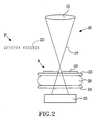
- Fig. 2 is a schematic view, illustrating an x-ray apparatus 20 according to the present invention.
- the apparatus 20 comprises an x-ray source 21; a collimator arrangement 22, compression paddles 23 and 24, and a detector assembly 25.
- the breast 26 to be examined (x-rayed) is placed between the compression paddles 23 and 24 and exposed to a pressure, which flattens it so that as much as the breast is exposed to the x-rays and detected by the detector assembly 25 and a sufficient contrast is obtained.
- the x-rays are denoted with 27.
- the collimator arrangement 22 is arranged to assume at least two positions, a parking position P and an active position A.
- the parking position the collimator is arranged in an area, which does not interfere with the positioning of the patient's breast between the compression paddles.
- This area can be an area outside the exposure area, preferably, by displacing and/or lifting the collimator arrangement from the exposure area. Displacement of the entire collimator arrangement is a lateral movement while the lifting is a vertical movement with respect to the plane of the drawing.
- the collimator arrangement 22 When the examination starts, the collimator arrangement 22 is placed in the parking position P. It must be high or offset enough to not disturb the nurse's adjustment of the breast 26.
- the collimator arrangement 22 moves downwards/sideway and stops in a position as close as possible to the compression plate 23.
- the collimator arrangement moves upwards/sideways with at least the speed of the compression plate to the parking position.
- the collimator motion towards the compression paddles can be initiated, e.g. by a dedicated switch after the positioning of the breast is carried out. It is important that the time the breast needs to be compressed is minimized. For this reason the movement of the collimator arrangement should be as fast as possible without causing patient anxiety.
- An exact parking position for the collimator is possible to configure, through commands of a control system, between approximately 18 cm from detector and approximately 50 cm from the detector.
- Fig. 3 is a schematic, but more detailed illustration, showing an x-ray apparatus 30 according to the invention.
- the apparatus 30 generally comprises a base 38, an imaging arm 381 pivotally attached to the base 38, an x-ray source 31 fixed to one end of the imaging arm 381, an image receiver or detector assembly 35 fixed at a second end of the imaging arm.
- the apparatus also includes compression paddle holders, which are slidably attached to the imaging arm.
- the compression paddle holder holds upper and lower compression paddles 33 and 34, respectively.
- a displaceable collimator arrangement 32 is arranged on a collimator arm 39.
- the detector assembly 35 is integrated with the lower compression paddle 34.
- the collimator holder arm 39 is arranged to displace the collimator arrangement 32 by sliding the collimator in a vertical direction and also it can comprise a telescopic structure to displace the collimator arrangement horizontally.
- the collimator arrangement 32 is situated in its parking position.
- the invention is not limited to mammography and can be used in any type of x-ray imaging apparatuses, using semiconducting or gaseous detectors or x-ray film.
Landscapes
- Health & Medical Sciences (AREA)
- Life Sciences & Earth Sciences (AREA)
- Engineering & Computer Science (AREA)
- Physics & Mathematics (AREA)
- Medical Informatics (AREA)
- High Energy & Nuclear Physics (AREA)
- Surgery (AREA)
- Public Health (AREA)
- Optics & Photonics (AREA)
- Pathology (AREA)
- Radiology & Medical Imaging (AREA)
- Biomedical Technology (AREA)
- Heart & Thoracic Surgery (AREA)
- Molecular Biology (AREA)
- Biophysics (AREA)
- Animal Behavior & Ethology (AREA)
- General Health & Medical Sciences (AREA)
- Nuclear Medicine, Radiotherapy & Molecular Imaging (AREA)
- Veterinary Medicine (AREA)
- Spectroscopy & Molecular Physics (AREA)
- General Engineering & Computer Science (AREA)
- General Physics & Mathematics (AREA)
- Dentistry (AREA)
- Oral & Maxillofacial Surgery (AREA)
- Apparatus For Radiation Diagnosis (AREA)
- Radiography Using Non-Light Waves (AREA)
- Radiation-Therapy Devices (AREA)
- Physical Deposition Of Substances That Are Components Of Semiconductor Devices (AREA)
- Surgical Instruments (AREA)
Abstract
Description
- The present invention enables scanned-slit x-ray imaging in mammography in the sense that for the first time a high spatial resolution image can be registered without compromising the ergonomics in positioning the breast. It further relates to a beam collimator arrangement consisting of one or several collimators in an x-ray apparatus shaping the x-ray beam to hit the active detector area (pre-collimator) and to remove scattered x-rays (aft collimator). It further comprises: an x-ray source; an x-ray image receiver positioned to receive x-rays from the x-ray source; means for positioning the object to be examined, the means being positionable between the x-ray source and the x-ray image receiver; and said pre collimator positioned between the x-ray source and the means for positioning the object.
- When carrying out scanned-slit mammography, one essential problem is placing the breast of a patient in right position while at the same time positioning the moving collimator is as close as possible to the breast to obtain a high image quality in terms of spatial resolution.
- Fig. 1 a is a schematic side view of a digital
mammography x-ray equipment 10 comprising anx-ray source 11, acollimator arrangement 12,compression paddles detector assembly 15. X-rays are denoted with 17. - The
breast 16 to be examined (x-rayed) is placed between thecompression paddles - As illustrated in Figs. 1a and 1b, the
collimator arrangement 12 must be placed as close as possible to theupper compression paddle 12. As indicated in Fig. 1a the image quality will be compromised if this is not the case, due to size of the x-ray source that will be imaged on the detector through the slit the spatial resolution bl will be deteriorated if the collimator is moved away from the object. This is only true in one dimension, the dimension orthogonal to the slit, as indicated in Fig. 1b. Thus, when placing the breast in the examining position, one must avoid the collimator arrangement, and when the examining starts the collimator must be placed as close as possible to and above the upper paddle. - EP 0417 965 discloses a method and apparatus for improving imaging in an X-ray mammography machine having a controllable X-ray source incorporates apparatus for directing the X-ray beam in a preselected configuration onto at least a portion of a target area. The creation intensity of the beam is detected in each of a plurality of substantially equal segments of the target area and a first segment of lowest radiation intensity is identified. The X-ray source is adjusted to establish a predetermined radiation intensity in the identified first segment. Second segments are then identified each having a radiation intensity greater than a predetermined percentage of the radiation intensity in the identified first segment. The radiation intensity directed toward the identified second segments is then automatically attenuated by a control system responsive to the radiation intensity detected in the second segments. The attenuation is achieved by moving collimators into the beam so as to reduce the radiation directed towards the second segments. The beam is scanned over the target and continuously adjusted in accordance with the radiation detected in each of the segments of the beam. In this manner, each area of the target receives just sufficient radiation to provide proper imaging without overexposing area of the target, which have less attenuation than other areas. Thus, the object of this invention is to obtain attenuation by horizontally displacing the collimator.
- A mammography apparatus for obtaining mammography images with optimal beam collimation is disclosed in US 5,627,869. Proportional control of collimator element position based upon compression paddle position and dimension inputs is provided to obtain optimal collimation of the X-ray beam for a desired imaging technique and compressed breast thickness. Relevant objects of this invention are: to provide a mammography apparatus with an X-ray beam collimator that is automatically adjusted to provide an appropriately collimated X-ray beam for any magnification factor, and to provide a mammography apparatus with an X-ray beam collimator that is automatically adjusted to provide an X-ray beam that is appropriately collimated for any magnification factor for a breast of any thickness using a compression paddle of any dimension. Hence, the collimator is provided with collimator blades, which are controlled to be displaced in horizontal direction.
- US 4,203,037discloses an apparatus for exposing an object to x-ray radiation including adjustable object supporting and compressing means and first collimator means having an opening and being disposed between the x-ray generator and the object supporting means.
Second collimator means having an opening and being disposed between the obj ect supporting means and x-ray detecting means. Means are provided for moving the first and second collimator means in such fashion as to maintain alignment between the openings therein and the x-ray generator, in order to sequentially expose portions of the object of x-ray passing through the first collimator means and permit such x-ray to pass through the opening in a second collimator means and impinge upon the x-ray detecting means. The object supporting and compressing means is preferably structurally independent of the collimator means. The x-ray detecting means preferably takes the form of a highly sensitive detector such as a film-screen cassette or a self-scanning array of photodiodes optically coupled to scintillator means. - Thus, the main object of the present invention is to provide a collimator arrangement and an x-ray apparatus employing such a collimator arrangement that solves the problems associated with the prior art and allow a working field for the nurse or other personal that is free from obstacles. Another object of the present invention is to provide a collimator arrangement that can be placed as closes as possible to the object to be examined during the exposure.
- Therefore the initially mentioned collimator arrangement is arranged on a carrying structure to displace the beam collimator arrangement between a first position when no x-ray exposure is conducted and a second position right before x-ray exposure is initiated and during the x-ray exposure. Preferably, the second position is in a substantially short distance from said compressing means. For flexibility, said displacement is in lateral and or horizontal direction.
- The invention also relates to a mammography apparatus as defined in claim 1 and a method in a mammography apparatus as defined in claim 4.
- In the following, the invention will be further described in a non-limiting way with reference to the accompanying drawings in which:
- Figs. 1a;1b
- are schematic illustrations of an x-ray apparatus according to priori art,
- Fig 2
- illustrates in a schematic way an embodiment of an x-ray apparatus according to the present invention, and
- Fig 3
- illustrates in a schematic way a more detailed embodiment of an x-ray apparatus according to the present invention.
- Fig. 2 is a schematic view, illustrating an
x-ray apparatus 20 according to the present invention. Theapparatus 20 comprises anx-ray source 21; acollimator arrangement 22,compression paddles detector assembly 25. Thebreast 26 to be examined (x-rayed) is placed between thecompression paddles detector assembly 25 and a sufficient contrast is obtained. The x-rays are denoted with 27. - The
collimator arrangement 22 is arranged to assume at least two positions, a parking position P and an active position A. In the parking position the collimator is arranged in an area, which does not interfere with the positioning of the patient's breast between the compression paddles. This area can be an area outside the exposure area, preferably, by displacing and/or lifting the collimator arrangement from the exposure area. Displacement of the entire collimator arrangement is a lateral movement while the lifting is a vertical movement with respect to the plane of the drawing. - When the examination starts, the
collimator arrangement 22 is placed in the parking position P. It must be high or offset enough to not disturb the nurse's adjustment of thebreast 26. When the compression is completed and the exposure to x-ray is to be initiated, thecollimator arrangement 22 moves downwards/sideway and stops in a position as close as possible to thecompression plate 23. When the exposure is completed the collimator arrangement moves upwards/sideways with at least the speed of the compression plate to the parking position. The collimator motion towards the compression paddles can be initiated, e.g. by a dedicated switch after the positioning of the breast is carried out. It is important that the time the breast needs to be compressed is minimized. For this reason the movement of the collimator arrangement should be as fast as possible without causing patient anxiety. An exact parking position for the collimator is possible to configure, through commands of a control system, between approximately 18 cm from detector and approximately 50 cm from the detector In particular, when multi-slits collimators are used, it is important that the collimator is placed close to the object to be examined. In this case, the resolution of the resultant image is deteriorated in a direction perpendicular to the collimator's slits. - Fig. 3 is a schematic, but more detailed illustration, showing an
x-ray apparatus 30 according to the invention. Theapparatus 30 generally comprises abase 38, animaging arm 381 pivotally attached to thebase 38, an x-ray source 31 fixed to one end of theimaging arm 381, an image receiver ordetector assembly 35 fixed at a second end of the imaging arm. The apparatus also includes compression paddle holders, which are slidably attached to the imaging arm. The compression paddle holder holds upper and lower compression paddles 33 and 34, respectively. Adisplaceable collimator arrangement 32 is arranged on acollimator arm 39. According to this embodiment, thedetector assembly 35 is integrated with thelower compression paddle 34. - The
collimator holder arm 39 is arranged to displace thecollimator arrangement 32 by sliding the collimator in a vertical direction and also it can comprise a telescopic structure to displace the collimator arrangement horizontally. In Fig. 3, thecollimator arrangement 32 is situated in its parking position. - The invention is not limited to mammography and can be used in any type of x-ray imaging apparatuses, using semiconducting or gaseous detectors or x-ray film.
- The invention is not limited to the shown embodiments; it can be varied in a number of ways without departing from the scope of the appended claims.
Claims (4)
- A mammography apparatus (20, 30) comprising:o an X-ray source (21, 31);o an X-ray image receiver (25, 35) positioned to receive X-rays from the X-ray source;o first and second means (23, 33; 24; 34) for compressing tissue, said means being arranged to be positioned between the X-ray source and the X-ray image receiver, said means further having a compression surface of predetermined dimension;o a beam collimator (22, 32) positioned between the X-ray source and said means for compressing tissue;characterized in
that said apparatus further comprises means (39) for displacing said beam collimator (22, 32) between a first position (P) outside the exposure area when no X-ray exposure is conducted and a second position (A) near the tissue before X-ray exposure is initiated and that said first position is vertically and horizontally displaced with respect to said second position. - The apparatus of claim 1,
characterised in
that said second position is in a substantially short distance from said compressing means (23, 33). - The apparatus of claim 1,
characterised in that the first position (P) is located vertically above the second position (A). - A method in a mammography apparatus (20, 30), said apparatus comprising:o an X-ray source (21,31);o an X-ray image receiver (25, 35) positioned to receive X-rays from the X-ray source;o first and second means (23, 33; 24; 34) for compressing tissue, said means being arranged to be positioned between the X-ray source and the X-ray image receiver, said means further having a compression surface of predetermined dimension;o a beam collimator (22, 32) positioned between the X-ray source and said means for compressing tissue;o means (39) for displacing said beam collimator (22, 32)the method comprising the steps of:placing said means (39) in a first position (P) outside the exposure area when no X-ray exposure is conducted andplacing said means (39) a second position (A) near the tissue before X-ray exposure is initiated, wherein said first position is vertically and horizontally displaced with respect to said second position.
Applications Claiming Priority (5)
| Application Number | Priority Date | Filing Date | Title |
|---|---|---|---|
| US26815601P | 2001-02-12 | 2001-02-12 | |
| SE0100470A SE523512C2 (en) | 2001-02-12 | 2001-02-12 | Beam collimator arrangement for scanned-slot mammography has x-ray source, x-ray image receiver and female breast compression paddles |
| SE0100470 | 2001-02-12 | ||
| US268156P | 2001-02-12 | ||
| PCT/SE2002/000238 WO2002065209A1 (en) | 2001-02-12 | 2002-02-12 | Collimator arrangement |
Publications (2)
| Publication Number | Publication Date |
|---|---|
| EP1360550A1 EP1360550A1 (en) | 2003-11-12 |
| EP1360550B1 true EP1360550B1 (en) | 2007-01-03 |
Family
ID=26655388
Family Applications (1)
| Application Number | Title | Priority Date | Filing Date |
|---|---|---|---|
| EP02711603A Expired - Lifetime EP1360550B1 (en) | 2001-02-12 | 2002-02-12 | Collimator arrangement |
Country Status (5)
| Country | Link |
|---|---|
| EP (1) | EP1360550B1 (en) |
| JP (1) | JP4102669B2 (en) |
| AT (1) | ATE350690T1 (en) |
| DE (1) | DE60217296T2 (en) |
| WO (1) | WO2002065209A1 (en) |
Families Citing this family (2)
| Publication number | Priority date | Publication date | Assignee | Title |
|---|---|---|---|---|
| US7302031B2 (en) | 2005-10-27 | 2007-11-27 | Sectra Mamea Ab | Method and arrangement relating to X-ray imaging |
| BR112013014572A2 (en) * | 2010-12-13 | 2016-09-20 | Philips Digital Mammography Sweden Ab | x-ray apparatus, method for imaging an object on an x-ray apparatus and collimating device |
Family Cites Families (7)
| Publication number | Priority date | Publication date | Assignee | Title |
|---|---|---|---|---|
| US4203037A (en) * | 1977-08-01 | 1980-05-13 | University Of Pittsburgh | Collimated radiation apparatus |
| DE3236081A1 (en) * | 1982-09-29 | 1984-03-29 | Siemens AG, 1000 Berlin und 8000 München | RECORDING DEVICE |
| SE459150B (en) * | 1986-09-19 | 1989-06-12 | Anders Wallner | DEVICE FOR MAMMOGRAPHIC STEREOTACTIC PUNCTION OF PATHOLOGICAL CHANGES IN THE FEMALE BREAST |
| US4969174A (en) * | 1989-09-06 | 1990-11-06 | General Electric Company | Scanning mammography system with reduced scatter radiation |
| US5627869A (en) * | 1995-11-22 | 1997-05-06 | Thermotrex Corporation | Mammography apparatus with proportional collimation |
| WO2000015112A1 (en) * | 1998-09-17 | 2000-03-23 | Quanta Vision, Inc. | Reduced-angle mammography device and variants |
| DE19939678A1 (en) * | 1999-08-21 | 2001-02-22 | Provotec Gmbh & Co Kg Roentgen | Moving x-ray grid for digital x-ray image detector and cassette centering device for two x-ray imaging media has upper part which can pivot 90 degrees to lower part |
-
2002
- 2002-02-12 EP EP02711603A patent/EP1360550B1/en not_active Expired - Lifetime
- 2002-02-12 DE DE60217296T patent/DE60217296T2/en not_active Expired - Lifetime
- 2002-02-12 JP JP2002564667A patent/JP4102669B2/en not_active Expired - Lifetime
- 2002-02-12 AT AT02711603T patent/ATE350690T1/en not_active IP Right Cessation
- 2002-02-12 WO PCT/SE2002/000238 patent/WO2002065209A1/en not_active Ceased
Also Published As
| Publication number | Publication date |
|---|---|
| JP2004526191A (en) | 2004-08-26 |
| DE60217296D1 (en) | 2007-02-15 |
| JP4102669B2 (en) | 2008-06-18 |
| WO2002065209A8 (en) | 2004-04-15 |
| ATE350690T1 (en) | 2007-01-15 |
| DE60217296T2 (en) | 2007-10-25 |
| EP1360550A1 (en) | 2003-11-12 |
| WO2002065209A1 (en) | 2002-08-22 |
Similar Documents
| Publication | Publication Date | Title |
|---|---|---|
| US11317878B2 (en) | Mammography system and method employing offset compression paddles, automatic collimation, and retractable anti-scatter grid | |
| EP1485024B1 (en) | X-ray apparatus provided with a positionally adjustable x-ray detector | |
| US7688940B2 (en) | Mammography system and method employing offset compression paddles, automatic collimation, and retractable anti-scatter grid | |
| US6292531B1 (en) | Methods and apparatus for generating depth information mammography images | |
| US7676021B2 (en) | Radiation imaging apparatus | |
| US5594769A (en) | Method and apparatus for obtaining stereotactic mammographic guided needle breast biopsies | |
| US6848826B2 (en) | Mammography apparatus and method | |
| JP5156186B2 (en) | Slot scanning configuration based on flat panel detector | |
| JP4522630B2 (en) | Digital X-ray scanning device | |
| US7170975B2 (en) | Method for operating a computed tomography apparatus having a diaphragm at the radiation detector | |
| US7676019B2 (en) | Compression arrangement | |
| US20140016742A1 (en) | Collimator arrangement and method | |
| EP0471096B1 (en) | Industrial computed tomography apparatus | |
| JP2001043993A (en) | Tube current adjusting method and device and x-ray ct device | |
| JP3977624B2 (en) | X-ray computed tomography system | |
| US7664223B1 (en) | Collimator element | |
| WO2002065209A1 (en) | Collimator arrangement | |
| JPH05269122A (en) | X-ray CT system | |
| JP2594106B2 (en) | X-ray equipment | |
| JP5259949B2 (en) | X-ray CT system | |
| JPH0312136A (en) | X-ray ct instrument | |
| SE523512C2 (en) | Beam collimator arrangement for scanned-slot mammography has x-ray source, x-ray image receiver and female breast compression paddles | |
| JP2005040328A (en) | Radiation image processing device | |
| WO2019225915A1 (en) | Digital breast tomosynthesis device capable of controlling position of x-ray focus | |
| JPH07194586A (en) | X-ray CT apparatus and collimator for X-ray CT apparatus |
Legal Events
| Date | Code | Title | Description |
|---|---|---|---|
| PUAI | Public reference made under article 153(3) epc to a published international application that has entered the european phase |
Free format text: ORIGINAL CODE: 0009012 |
|
| 17P | Request for examination filed |
Effective date: 20030710 |
|
| AK | Designated contracting states |
Kind code of ref document: A1 Designated state(s): AT BE CH CY DE DK ES FI FR GB GR IE IT LI LU MC NL PT SE TR |
|
| AX | Request for extension of the european patent |
Extension state: AL LT LV MK RO SI |
|
| RIN1 | Information on inventor provided before grant (corrected) |
Inventor name: LAMMROTH, THERESA Inventor name: RAPP, LENNART Inventor name: DANIELSSON, MATS |
|
| GRAP | Despatch of communication of intention to grant a patent |
Free format text: ORIGINAL CODE: EPIDOSNIGR1 |
|
| GRAS | Grant fee paid |
Free format text: ORIGINAL CODE: EPIDOSNIGR3 |
|
| RAP1 | Party data changed (applicant data changed or rights of an application transferred) |
Owner name: ARCOMA AB Owner name: SECTRA MAMEA AB |
|
| GRAA | (expected) grant |
Free format text: ORIGINAL CODE: 0009210 |
|
| AK | Designated contracting states |
Kind code of ref document: B1 Designated state(s): AT BE CH CY DE DK ES FI FR GB GR IE IT LI LU MC NL PT SE TR |
|
| PG25 | Lapsed in a contracting state [announced via postgrant information from national office to epo] |
Ref country code: LI Free format text: LAPSE BECAUSE OF FAILURE TO SUBMIT A TRANSLATION OF THE DESCRIPTION OR TO PAY THE FEE WITHIN THE PRESCRIBED TIME-LIMIT Effective date: 20070103 Ref country code: DK Free format text: LAPSE BECAUSE OF FAILURE TO SUBMIT A TRANSLATION OF THE DESCRIPTION OR TO PAY THE FEE WITHIN THE PRESCRIBED TIME-LIMIT Effective date: 20070103 Ref country code: FI Free format text: LAPSE BECAUSE OF FAILURE TO SUBMIT A TRANSLATION OF THE DESCRIPTION OR TO PAY THE FEE WITHIN THE PRESCRIBED TIME-LIMIT Effective date: 20070103 Ref country code: NL Free format text: LAPSE BECAUSE OF FAILURE TO SUBMIT A TRANSLATION OF THE DESCRIPTION OR TO PAY THE FEE WITHIN THE PRESCRIBED TIME-LIMIT Effective date: 20070103 Ref country code: AT Free format text: LAPSE BECAUSE OF FAILURE TO SUBMIT A TRANSLATION OF THE DESCRIPTION OR TO PAY THE FEE WITHIN THE PRESCRIBED TIME-LIMIT Effective date: 20070103 Ref country code: CH Free format text: LAPSE BECAUSE OF FAILURE TO SUBMIT A TRANSLATION OF THE DESCRIPTION OR TO PAY THE FEE WITHIN THE PRESCRIBED TIME-LIMIT Effective date: 20070103 |
|
| REG | Reference to a national code |
Ref country code: GB Ref legal event code: FG4D |
|
| REF | Corresponds to: |
Ref document number: 60217296 Country of ref document: DE Date of ref document: 20070215 Kind code of ref document: P |
|
| REG | Reference to a national code |
Ref country code: IE Ref legal event code: FG4D |
|
| PG25 | Lapsed in a contracting state [announced via postgrant information from national office to epo] |
Ref country code: MC Free format text: LAPSE BECAUSE OF NON-PAYMENT OF DUE FEES Effective date: 20070228 |
|
| PG25 | Lapsed in a contracting state [announced via postgrant information from national office to epo] |
Ref country code: SE Free format text: LAPSE BECAUSE OF FAILURE TO SUBMIT A TRANSLATION OF THE DESCRIPTION OR TO PAY THE FEE WITHIN THE PRESCRIBED TIME-LIMIT Effective date: 20070403 |
|
| PG25 | Lapsed in a contracting state [announced via postgrant information from national office to epo] |
Ref country code: ES Free format text: LAPSE BECAUSE OF FAILURE TO SUBMIT A TRANSLATION OF THE DESCRIPTION OR TO PAY THE FEE WITHIN THE PRESCRIBED TIME-LIMIT Effective date: 20070414 |
|
| PG25 | Lapsed in a contracting state [announced via postgrant information from national office to epo] |
Ref country code: PT Free format text: LAPSE BECAUSE OF FAILURE TO SUBMIT A TRANSLATION OF THE DESCRIPTION OR TO PAY THE FEE WITHIN THE PRESCRIBED TIME-LIMIT Effective date: 20070604 |
|
| NLV1 | Nl: lapsed or annulled due to failure to fulfill the requirements of art. 29p and 29m of the patents act | ||
| REG | Reference to a national code |
Ref country code: CH Ref legal event code: PL |
|
| ET | Fr: translation filed | ||
| REG | Reference to a national code |
Ref country code: FR Ref legal event code: TP |
|
| PLBE | No opposition filed within time limit |
Free format text: ORIGINAL CODE: 0009261 |
|
| STAA | Information on the status of an ep patent application or granted ep patent |
Free format text: STATUS: NO OPPOSITION FILED WITHIN TIME LIMIT |
|
| 26N | No opposition filed |
Effective date: 20071005 |
|
| GBPC | Gb: european patent ceased through non-payment of renewal fee |
Effective date: 20070403 |
|
| PG25 | Lapsed in a contracting state [announced via postgrant information from national office to epo] |
Ref country code: BE Free format text: LAPSE BECAUSE OF FAILURE TO SUBMIT A TRANSLATION OF THE DESCRIPTION OR TO PAY THE FEE WITHIN THE PRESCRIBED TIME-LIMIT Effective date: 20070103 |
|
| PG25 | Lapsed in a contracting state [announced via postgrant information from national office to epo] |
Ref country code: IE Free format text: LAPSE BECAUSE OF NON-PAYMENT OF DUE FEES Effective date: 20070212 |
|
| PG25 | Lapsed in a contracting state [announced via postgrant information from national office to epo] |
Ref country code: GR Free format text: LAPSE BECAUSE OF FAILURE TO SUBMIT A TRANSLATION OF THE DESCRIPTION OR TO PAY THE FEE WITHIN THE PRESCRIBED TIME-LIMIT Effective date: 20070404 Ref country code: IT Free format text: LAPSE BECAUSE OF FAILURE TO SUBMIT A TRANSLATION OF THE DESCRIPTION OR TO PAY THE FEE WITHIN THE PRESCRIBED TIME-LIMIT Effective date: 20070103 Ref country code: GB Free format text: LAPSE BECAUSE OF NON-PAYMENT OF DUE FEES Effective date: 20070403 |
|
| PG25 | Lapsed in a contracting state [announced via postgrant information from national office to epo] |
Ref country code: CY Free format text: LAPSE BECAUSE OF FAILURE TO SUBMIT A TRANSLATION OF THE DESCRIPTION OR TO PAY THE FEE WITHIN THE PRESCRIBED TIME-LIMIT Effective date: 20070103 |
|
| PG25 | Lapsed in a contracting state [announced via postgrant information from national office to epo] |
Ref country code: LU Free format text: LAPSE BECAUSE OF NON-PAYMENT OF DUE FEES Effective date: 20070212 |
|
| PG25 | Lapsed in a contracting state [announced via postgrant information from national office to epo] |
Ref country code: TR Free format text: LAPSE BECAUSE OF FAILURE TO SUBMIT A TRANSLATION OF THE DESCRIPTION OR TO PAY THE FEE WITHIN THE PRESCRIBED TIME-LIMIT Effective date: 20070103 |
|
| REG | Reference to a national code |
Ref country code: FR Ref legal event code: CA Effective date: 20130128 Ref country code: FR Ref legal event code: CD Owner name: PHILIPS DIGITAL MAMMOGRAPHY SWEDEN AB, SE Effective date: 20130128 |
|
| REG | Reference to a national code |
Ref country code: DE Ref legal event code: R082 Ref document number: 60217296 Country of ref document: DE Representative=s name: MEISSNER, BOLTE & PARTNER GBR, DE Ref country code: DE Ref legal event code: R081 Ref document number: 60217296 Country of ref document: DE Owner name: PHILIPS DIGITAL MAMMOGRAPHY SWEDEN AB, SE Free format text: FORMER OWNER: SECTRA MAMEA AB, KISTA, SE Ref country code: DE Ref legal event code: R082 Ref document number: 60217296 Country of ref document: DE Representative=s name: MEISSNER BOLTE PATENTANWAELTE RECHTSANWAELTE P, DE |
|
| REG | Reference to a national code |
Ref country code: FR Ref legal event code: PLFP Year of fee payment: 15 |
|
| REG | Reference to a national code |
Ref country code: FR Ref legal event code: PLFP Year of fee payment: 16 |
|
| REG | Reference to a national code |
Ref country code: FR Ref legal event code: PLFP Year of fee payment: 17 |
|
| PGFP | Annual fee paid to national office [announced via postgrant information from national office to epo] |
Ref country code: FR Payment date: 20210223 Year of fee payment: 20 |
|
| PGFP | Annual fee paid to national office [announced via postgrant information from national office to epo] |
Ref country code: DE Payment date: 20210225 Year of fee payment: 20 |
|
| REG | Reference to a national code |
Ref country code: DE Ref legal event code: R071 Ref document number: 60217296 Country of ref document: DE |