EP1359659A2 - Alternator for vehicle - Google Patents
Alternator for vehicle Download PDFInfo
- Publication number
- EP1359659A2 EP1359659A2 EP03008717A EP03008717A EP1359659A2 EP 1359659 A2 EP1359659 A2 EP 1359659A2 EP 03008717 A EP03008717 A EP 03008717A EP 03008717 A EP03008717 A EP 03008717A EP 1359659 A2 EP1359659 A2 EP 1359659A2
- Authority
- EP
- European Patent Office
- Prior art keywords
- terminal
- electrical connection
- connection terminal
- alternator
- copper
- Prior art date
- Legal status (The legal status is an assumption and is not a legal conclusion. Google has not performed a legal analysis and makes no representation as to the accuracy of the status listed.)
- Granted
Links
- 238000003466 welding Methods 0.000 claims abstract description 54
- RYGMFSIKBFXOCR-UHFFFAOYSA-N Copper Chemical compound [Cu] RYGMFSIKBFXOCR-UHFFFAOYSA-N 0.000 claims description 21
- 229910052802 copper Inorganic materials 0.000 claims description 21
- 239000010949 copper Substances 0.000 claims description 21
- 229910000881 Cu alloy Inorganic materials 0.000 claims description 17
- 229910052751 metal Inorganic materials 0.000 claims description 10
- 239000002184 metal Substances 0.000 claims description 10
- 239000000463 material Substances 0.000 claims description 6
- 239000004065 semiconductor Substances 0.000 claims description 4
- 230000035515 penetration Effects 0.000 abstract description 10
- 230000008018 melting Effects 0.000 abstract 1
- 238000002844 melting Methods 0.000 abstract 1
- 230000005855 radiation Effects 0.000 abstract 1
- 239000004020 conductor Substances 0.000 description 5
- WFKWXMTUELFFGS-UHFFFAOYSA-N tungsten Chemical compound [W] WFKWXMTUELFFGS-UHFFFAOYSA-N 0.000 description 5
- 229910052721 tungsten Inorganic materials 0.000 description 5
- 239000010937 tungsten Substances 0.000 description 5
- 239000007789 gas Substances 0.000 description 4
- 239000011261 inert gas Substances 0.000 description 3
- XLYOFNOQVPJJNP-UHFFFAOYSA-N water Substances O XLYOFNOQVPJJNP-UHFFFAOYSA-N 0.000 description 3
- 238000005452 bending Methods 0.000 description 1
- 238000004140 cleaning Methods 0.000 description 1
- 238000010276 construction Methods 0.000 description 1
- 238000001816 cooling Methods 0.000 description 1
- 239000000498 cooling water Substances 0.000 description 1
- 230000000694 effects Effects 0.000 description 1
- 238000002474 experimental method Methods 0.000 description 1
- 238000004519 manufacturing process Methods 0.000 description 1
- 150000002739 metals Chemical class 0.000 description 1
- 238000003825 pressing Methods 0.000 description 1
- 230000001105 regulatory effect Effects 0.000 description 1
- 239000011347 resin Substances 0.000 description 1
- 229920005989 resin Polymers 0.000 description 1
- 238000007789 sealing Methods 0.000 description 1
Images



Classifications
-
- H—ELECTRICITY
- H02—GENERATION; CONVERSION OR DISTRIBUTION OF ELECTRIC POWER
- H02K—DYNAMO-ELECTRIC MACHINES
- H02K15/00—Processes or apparatus specially adapted for manufacturing, assembling, maintaining or repairing of dynamo-electric machines
-
- H—ELECTRICITY
- H02—GENERATION; CONVERSION OR DISTRIBUTION OF ELECTRIC POWER
- H02K—DYNAMO-ELECTRIC MACHINES
- H02K11/00—Structural association of dynamo-electric machines with electric components or with devices for shielding, monitoring or protection
- H02K11/04—Structural association of dynamo-electric machines with electric components or with devices for shielding, monitoring or protection for rectification
- H02K11/049—Rectifiers associated with stationary parts, e.g. stator cores
- H02K11/05—Rectifiers associated with casings, enclosures or brackets
Definitions
- the present invention relates to an alternator for a vehicle, and more particularly to an improvement of a weldment (weld joined portion) at which a terminal of a semiconductor part (e.g., a diode used as a rectifying device) and an electrical connection terminal of a wiring conductor, for example, are connected to each other by welding.
- a weldment welding joined portion
- alternators In vehicular alternators (hereinafter referred to simply as "alternators") as disclosed in Japanese Unexamined Patent Application Publication Nos. 6-98511 and 62-55878, for example, resistance welding has been conventionally employed for connection between electrical members of the alternator (e.g., between a connecting member connected to a lead from a stator or a rotor of an alternator and a terminal of a semiconductor device).
- resistance welding is employed to connect copper-made pin-shaped (generally columnar) terminals of plural rectifying devices for rectifying three-phase AC power from the alternator and a steel-made terminal in the form of a flat plate, which is covered with an insulating member around it and which serves as a terminal for connecting the rectifying devices and supplying the rectified power to the vehicle side.
- connection terminal known as the related art generates a larger amount of heat as an output of the alternator increases, and has a problem that the insulating member and the rectifying devices may be damaged by the generated heat. To avoid such a problem, electrical resistance of the terminal for connection among the rectifying devices of the alternator having a large output must be reduced.
- Conceivable solutions for reducing the electrical resistance are to increase the size of a terminal shape and to change a material of the connection terminal to a good conductor such as copper.
- resistance welding is not suitable for connecting the copper-made terminal of each rectifying device and an electrical connection terminal which is also made of copper, and TIG (tungsten inert gas) welding (i.e., arc welding using a gas shielded non-consumable electrode) must be used.
- the above object is achieved by the feature that a portion for increasing a volume, e.g., a projection, is provided on a connecting member near its welded region to suppress an increase of the welding depth.
- a portion for increasing a volume e.g., a projection
- the above object is achieved by forming a projection near a position, at which a flat plate-shaped electrical connection terminal and a columnar terminal are joined to each other by welding, so as to project from a lateral surface of said flat plate-shaped electrical connection terminal.
- the above object is achieved by providing a molten metal capturing portion provided in a weld joined portion of the electrical connection terminal.
- the above object is achieved by providing a pair of heat radiating lugs near a weld joined portion of the electrical connection terminal so as to surround a rectifying device terminal.
- the above object is achieved by providing a thermal mass portion near a weld joined portion of the electrical connection terminal so as to suppress growth of a molten pool produced with welding.
- a pulley 2 for transmitting a driving force from an engine (not shown) to a rotor shaft 1 is disposed at an end of the rotor shaft 1, and a rotor 3 having claw-shaped magnetic poles, over which field coils 3a are wound, generates a revolving magnetic field with rotation of the pulley 2.
- the revolving magnetic field induces an electromotive force in three-phase stator coils 5 wound over respective cores of a stator 4, which is disposed around the rotor 3 with a gap left between them.
- the rotor shaft 1 is rotatably supported by bearings 6a, 6b, and the bearings 6a, 6b are in turn supported by brackets 7, 8, respectively.
- the cores of the stator 4 are supported by the bracket 8.
- the bracket 8 is provided with a water passage 8a through which cooling water is circulated to cool heat generating parts such as the stator coils 5.
- Gaskets 9a, 9b for sealing off the water passage 8a are disposed respectively at opposite ends of the water passage 8a.
- the gasket 9b is fixed together with a plate member 10 and a rear cover 11 in a sandwiched relation to the bracket 8 using bolts 12.
- a brush holder 14 for accommodating brushes 13a, 13b to supply field currents to the field coils 3a and a rectifier 15 for rectifying three-phase AC power generated in the stator coils 5 are both fixed to the plate member 10 using bolts 16a, 16b and nuts 17.
- the brushes 13a, 13b supply the field currents to the field coils 3a of the rotor 3 while being held in slide contact with respective current collecting rings 19 by pressing forces of springs 18a, 18b both accommodated in the brush holder 14.
- the field currents are regulated by a voltage regulator 25 accommodated in a part of the brush holder 14, and the voltage of the field currents is adjusted to a prescribed value.
- the rectifier 15 comprises a minus-side diode 23 fixed to a heat radiating plate 22, a plus-side diode 21 fixed to a heat radiating plate 20, and a connecting member 24 for connecting respective terminals 21a, 23a of the plus-side diode 21 and the minus-side diode 23 to each other.
- the connecting member 24 comprises a terminal member 24a and an insulating member 24b in which the terminal members 24a are partly embedded.
- the three-phase stator coils 5 are interconnected in the form of ⁇ - or Y-connection, and three or four leads 5a from the stator coils 5 are each connected to a terminal portion 24c as a part of the terminal member 24a of the connecting member 24 of the rectifier 15.
- the terminal 21a, 23a of the plus-side diode 21 or the minus-side diode 23 of the rectifier 15 is connected to another terminal portion 24d of the terminal member 24a, which is positioned oppositely away from the terminal portion 24c, and an AC current flows through the terminal member 24a.
- the terminal member 24a Because the terminal member 24a generates heat upon the current flowing through it, a material having small electrical resistance, e.g., copper, is selected as the terminal member 24a of an alternator for a large power. Also, because the terminal portion 24c of the terminal member 24a and the terminals 21a, 23a of the plus-side diode 21 and the minus-side diode 23 are both made of copper, resistance welding has a difficulty in connecting them to each other, and TIG welding is used for connection therebetween. The use of TIG welding requires dimensional accuracy of each terminal and a welding electrode, and a variation occurs in weld penetration (welding depth) depending on the dimensional accuracy.
- TIG welding requires dimensional accuracy of each terminal and a welding electrode, and a variation occurs in weld penetration (welding depth) depending on the dimensional accuracy.
- the terminal portion 24d of the terminal member 24a is not uniform in shape and is provided with projected lugs 24e in its intermediate position that is determined in consideration of the welding depth of from the terminal end.
- the projected lugs 24e have a different heat capacity from the other part of the terminal portion 24d. Accordingly, the projected lugs 24e limit the weld penetration, and even if there are large variations in distance between the welding electrode and each terminal and in dimensions of each terminal, the weld penetration is stopped at the position of the projected lugs 24e and the welding depth is stabilized.
- Another advantage is in that, by bending the projected lugs 24e of the terminal portion 24d of the terminal member 24a toward the side of the terminal 21a, 23a of the plus-side diode 21 or the minus-side diode 23, it is possible to easily position the terminal portion 24d of the terminal member 24a relative to the terminal 21a, 23a of the plus-side diode 21 or the minus-side diode 23.
- the heat radiating plates 20, 22, to which the plus-side diode 21 and the minus-side diode 23 are fixed respectively, are disposed in two steps one above the other in the height direction. Therefore, the distances from the positions, at which the plus-side diode 21 and the minus-side diode 23 are mounted, to respective welding positions differ from each other depending on which one of the plus-side diode 21 and the minus-side diode 23 is subjected to the welding.
- the connecting member 24 comprises the insulating member 24b made of an insulating resin, and an electrical connection conductor made of copper or a copper alloy and partly molded (embedded) in the insulating member 24b.
- the terminal member 24a is a part of the electrical connection conductor.
- the terminal member 24a is projected out of an edge of an insulating plate constituting the insulating member 24b, and a part of the terminal member 24a, which is bent at 90 degrees relative to the insulating plate of the insulating member 24b and extended from it, serves as the terminal portion 24d.
- the terminal portion 24d is extended in a juxtaposed relation to each of the terminals 21a, 23a of the plus-side diode 21 and the minus-side diode 23.
- the terminals 21a, 23a of the plus-side diode 21 and the minus-side diode 23 have lengths set different from each other such that terminal upper ends are located in positions at the same level.
- a pair of left and right projected lugs (projections) 24e projecting from each terminal portion 24d in the cross form are formed midway each of the terminal portions 24d at the same level.
- the terminals 21a, 23a of the plus-side diode 21 and the minus-side diode 23 are arranged adjacent to the respective terminal portions 24d.
- the terminals 21a, 23a and the terminal portions 24d are held in a closely contact state.
- the projected lugs 24e are slightly bent toward the terminal 21a or 23a so as to surround it.
- the amount by which the projected lugs 24e are bent is set to be the same regardless of the terminal type, and is adjusted to a value that has been determined based on experiments beforehand for each model in consideration of the effect of the projected lugs 24e limiting the metal penetration (welding depth of the metal) during the welding.
- a gas nozzle N of a welding device is moved toward a preset position between the projected lugs 24e and a distal end of the terminal portion 24d, and generates an arc A between a distal end of a tungsten electrode Tg and the terminal portions 24d.
- An inert gas G is ejected from the surroundings of a collet K, and the arc welding is performed in the inert gas G.
- a welding rod P is automatically inserted into the arc A by the welding device.
- the tungsten electrode Tg When the tungsten electrode Tg is set to a plus electrode, the weld penetration in a weldment is small, but a superior cleaning action is obtained in the welding position.
- the tungsten electrode Tg is set to a minus electrode, the weld penetration in a weldment is increased. In this embodiment, the welding is performed in the latter setting.
- the terminal portions 24d as a base material and the terminal 21a or 23a as a welding metal are molten, whereupon a molten pool S is produced.
- a molten pool S In the molten pool S, three kinds of metals including the metal of the welding rod fused together, and a metal joined layer is formed after cooling.
- the extent of growth of the molten pool S also differs correspondingly.
- the welding time is set such that a weld joined portion is surely formed even under the worst welding conditions. In a place where better welding conditions are satisfied, therefore, the molten pool S grows faster and spreads over a larger area.
- the inventors have discovered that, if there occurs a variation in growth of the molten pool, the resistance value is affected when looking at the weld joined portion as an electrical conductor.
- the principle of the effective solution resides in that a heat radiating portion having a large thermal mass is disposed near the weld joined portion in the direction of growth of the molten pool, whereby when the molten pool reaches the position of the heat radiating portion, further growth of the molten pool is prevented.
- the weld joined portion can be formed with even electrical resistance.
- quality of the weld joined portion in an alternator for a vehicle is ensured. For example, welding quality such as weld strength and weld penetration is stabilized. As a result, quality of individual alternators is stabilized. For example, a variation in electrical resistance value of the weld joined portion is reduced.
Landscapes
- Engineering & Computer Science (AREA)
- Power Engineering (AREA)
- Manufacturing & Machinery (AREA)
- Synchronous Machinery (AREA)
- Connections Effected By Soldering, Adhesion, Or Permanent Deformation (AREA)
- Butt Welding And Welding Of Specific Article (AREA)
- Manufacture Of Motors, Generators (AREA)
Abstract
Description
- The present invention relates to an alternator for a vehicle, and more particularly to an improvement of a weldment (weld joined portion) at which a terminal of a semiconductor part (e.g., a diode used as a rectifying device) and an electrical connection terminal of a wiring conductor, for example, are connected to each other by welding.
- In vehicular alternators (hereinafter referred to simply as "alternators") as disclosed in Japanese Unexamined Patent Application Publication Nos. 6-98511 and 62-55878, for example, resistance welding has been conventionally employed for connection between electrical members of the alternator (e.g., between a connecting member connected to a lead from a stator or a rotor of an alternator and a terminal of a semiconductor device). More specifically, resistance welding is employed to connect copper-made pin-shaped (generally columnar) terminals of plural rectifying devices for rectifying three-phase AC power from the alternator and a steel-made terminal in the form of a flat plate, which is covered with an insulating member around it and which serves as a terminal for connecting the rectifying devices and supplying the rectified power to the vehicle side.
- The above-described connection terminal known as the related art generates a larger amount of heat as an output of the alternator increases, and has a problem that the insulating member and the rectifying devices may be damaged by the generated heat. To avoid such a problem, electrical resistance of the terminal for connection among the rectifying devices of the alternator having a large output must be reduced.
- Conceivable solutions for reducing the electrical resistance are to increase the size of a terminal shape and to change a material of the connection terminal to a good conductor such as copper. When adopting the solution to change the terminal material from the standpoint of space, however, resistance welding is not suitable for connecting the copper-made terminal of each rectifying device and an electrical connection terminal which is also made of copper, and TIG (tungsten inert gas) welding (i.e., arc welding using a gas shielded non-consumable electrode) must be used.
- It is an object of the present invention to provide a terminal shape and a weld joined structure, which are suitable for connecting copper-made terminals to each other by TIG welding, and to provide an alternator for a vehicle having stable welding quality such as weld strength and weld penetration (welding depth).
- According to the present invention, the above object is achieved by the feature that a portion for increasing a volume, e.g., a projection, is provided on a connecting member near its welded region to suppress an increase of the welding depth.
- More specifically, the above object is achieved by forming a projection near a position, at which a flat plate-shaped electrical connection terminal and a columnar terminal are joined to each other by welding, so as to project from a lateral surface of said flat plate-shaped electrical connection terminal.
- Also, the above object is achieved by providing a molten metal capturing portion provided in a weld joined portion of the electrical connection terminal.
- Further, the above object is achieved by providing a pair of heat radiating lugs near a weld joined portion of the electrical connection terminal so as to surround a rectifying device terminal.
- Still further, the above object is achieved by providing a thermal mass portion near a weld joined portion of the electrical connection terminal so as to suppress growth of a molten pool produced with welding.
-
- Fig. 1 is a vertical sectional view showing one embodiment of an alternator for a vehicle in which the present invention is implemented;
- Fig. 2 is a right side view of the alternator of Fig. 1 in a state in which a rear cover is removed;
- Fig. 3 is a sectional view taken along the line A-A in Fig. 2;
- Fig. 4 is a sectional view taken along the line B-B in Fig. 2;
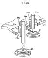
- Fig. 5 is a schematic view of a weld joined portion; and
- Fig. 6 is a schematic partial sectional view showing a state under welding.
-
- One embodiment of the present invention will be described below in more detail with reference to Figs. 1, 2, 3 and 4.
- A
pulley 2 for transmitting a driving force from an engine (not shown) to a rotor shaft 1 is disposed at an end of the rotor shaft 1, and arotor 3 having claw-shaped magnetic poles, over whichfield coils 3a are wound, generates a revolving magnetic field with rotation of thepulley 2. The revolving magnetic field induces an electromotive force in three-phase stator coils 5 wound over respective cores of astator 4, which is disposed around therotor 3 with a gap left between them. The rotor shaft 1 is rotatably supported bybearings bearings brackets stator 4 are supported by thebracket 8. Thebracket 8 is provided with awater passage 8a through which cooling water is circulated to cool heat generating parts such as thestator coils 5.Gaskets water passage 8a are disposed respectively at opposite ends of thewater passage 8a. Thegasket 9b is fixed together with aplate member 10 and arear cover 11 in a sandwiched relation to thebracket 8 usingbolts 12. Abrush holder 14 for accommodatingbrushes field coils 3a and arectifier 15 for rectifying three-phase AC power generated in thestator coils 5 are both fixed to theplate member 10 usingbolts nuts 17. Thebrushes field coils 3a of therotor 3 while being held in slide contact with respectivecurrent collecting rings 19 by pressing forces ofsprings brush holder 14. The field currents are regulated by avoltage regulator 25 accommodated in a part of thebrush holder 14, and the voltage of the field currents is adjusted to a prescribed value. Therectifier 15 comprises a minus-side diode 23 fixed to aheat radiating plate 22, a plus-side diode 21 fixed to aheat radiating plate 20, and a connectingmember 24 for connectingrespective terminals side diode 21 and the minus-side diode 23 to each other. The connectingmember 24 comprises aterminal member 24a and aninsulating member 24b in which theterminal members 24a are partly embedded. The three-phase stator coils 5 are interconnected in the form of Δ- or Y-connection, and three or fourleads 5a from thestator coils 5 are each connected to aterminal portion 24c as a part of theterminal member 24a of the connectingmember 24 of therectifier 15. Theterminal side diode 21 or the minus-side diode 23 of therectifier 15 is connected to anotherterminal portion 24d of theterminal member 24a, which is positioned oppositely away from theterminal portion 24c, and an AC current flows through theterminal member 24a. Because theterminal member 24a generates heat upon the current flowing through it, a material having small electrical resistance, e.g., copper, is selected as theterminal member 24a of an alternator for a large power. Also, because theterminal portion 24c of theterminal member 24a and theterminals side diode 21 and the minus-side diode 23 are both made of copper, resistance welding has a difficulty in connecting them to each other, and TIG welding is used for connection therebetween. The use of TIG welding requires dimensional accuracy of each terminal and a welding electrode, and a variation occurs in weld penetration (welding depth) depending on the dimensional accuracy. Theterminal portion 24d of theterminal member 24a is not uniform in shape and is provided with projectedlugs 24e in its intermediate position that is determined in consideration of the welding depth of from the terminal end. The projectedlugs 24e have a different heat capacity from the other part of theterminal portion 24d. Accordingly, the projectedlugs 24e limit the weld penetration, and even if there are large variations in distance between the welding electrode and each terminal and in dimensions of each terminal, the weld penetration is stopped at the position of the projectedlugs 24e and the welding depth is stabilized. - With this embodiment, since the weld penetration is stably set without being affected by the dimensional accuracy of the terminals, welding can be performed with stability in quality such as welding strength, and severe dimensional management is no longer required. As a result, an alternator can be provided which is relatively inexpensive and easy to manufacture.
- Another advantage is in that, by bending the projected
lugs 24e of theterminal portion 24d of theterminal member 24a toward the side of theterminal side diode 21 or the minus-side diode 23, it is possible to easily position theterminal portion 24d of theterminal member 24a relative to theterminal side diode 21 or the minus-side diode 23. - With reference to Figs. 5 and 6, a description is made in detail of how the
terminal 21a of the plus-side diode 21 fixed to theheat radiating plate 20 and theterminal 23a of the minus-side diode 23 fixed to theheat radiating plate 22 are welded to the electricalconnection terminal members 24a to 24e by arc welding using a gas shielded non-consumable electrode. Note that, in Figs. 5 and 6, principal parts are illustrated in exaggerated fashion with dimensions somewhat different from actual ones. - As shown in Figs. 3 and 4, the
heat radiating plates side diode 21 and the minus-side diode 23 are fixed respectively, are disposed in two steps one above the other in the height direction. Therefore, the distances from the positions, at which the plus-side diode 21 and the minus-side diode 23 are mounted, to respective welding positions differ from each other depending on which one of the plus-side diode 21 and the minus-side diode 23 is subjected to the welding. - In this embodiment, the connecting
member 24 comprises theinsulating member 24b made of an insulating resin, and an electrical connection conductor made of copper or a copper alloy and partly molded (embedded) in theinsulating member 24b. Theterminal member 24a is a part of the electrical connection conductor. - The
terminal member 24a is projected out of an edge of an insulating plate constituting the insulatingmember 24b, and a part of theterminal member 24a, which is bent at 90 degrees relative to the insulating plate of the insulatingmember 24b and extended from it, serves as theterminal portion 24d. Theterminal portion 24d is extended in a juxtaposed relation to each of theterminals side diode 21 and the minus-side diode 23. - The
terminals side diode 21 and the minus-side diode 23 have lengths set different from each other such that terminal upper ends are located in positions at the same level. - A pair of left and right projected lugs (projections) 24e projecting from each
terminal portion 24d in the cross form are formed midway each of theterminal portions 24d at the same level. - The
terminals side diode 21 and the minus-side diode 23 are arranged adjacent to the respectiveterminal portions 24d. Preferably, theterminals terminal portions 24d are held in a closely contact state. - In that condition, the projected
lugs 24e are slightly bent toward theterminal lugs 24e are bent is set to be the same regardless of the terminal type, and is adjusted to a value that has been determined based on experiments beforehand for each model in consideration of the effect of the projectedlugs 24e limiting the metal penetration (welding depth of the metal) during the welding. - A gas nozzle N of a welding device is moved toward a preset position between the projected
lugs 24e and a distal end of theterminal portion 24d, and generates an arc A between a distal end of a tungsten electrode Tg and theterminal portions 24d. - An inert gas G is ejected from the surroundings of a collet K, and the arc welding is performed in the inert gas G. A welding rod P is automatically inserted into the arc A by the welding device.
- When the tungsten electrode Tg is set to a plus electrode, the weld penetration in a weldment is small, but a superior cleaning action is obtained in the welding position.
- On the other hand, when the tungsten electrode Tg is set to a minus electrode, the weld penetration in a weldment is increased. In this embodiment, the welding is performed in the latter setting.
- When the arc A occurs, the
terminal portions 24d as a base material and the terminal 21a or 23a as a welding metal are molten, whereupon a molten pool S is produced. In the molten pool S, three kinds of metals including the metal of the welding rod fused together, and a metal joined layer is formed after cooling. - Since the distance and angle of the tungsten electrode Tg relative to a welded region differ, though just a small, depending on each of welded regions, the extent of growth of the molten pool S also differs correspondingly. The welding time is set such that a weld joined portion is surely formed even under the worst welding conditions. In a place where better welding conditions are satisfied, therefore, the molten pool S grows faster and spreads over a larger area. The inventors have discovered that, if there occurs a variation in growth of the molten pool, the resistance value is affected when looking at the weld joined portion as an electrical conductor.
- Then, the inventors have made endeavors to find a solution for keeping the growth of the molten pool as even as possible. The principle of the effective solution resides in that a heat radiating portion having a large thermal mass is disposed near the weld joined portion in the direction of growth of the molten pool, whereby when the molten pool reaches the position of the heat radiating portion, further growth of the molten pool is prevented.
- Based on that principle, even when a relatively long welding time is required depending on the welded region, the growth of the molten pool is surely stopped at the position of the heat radiating portion, and an area over which the weld joined metal portion spreads becomes more uniform than in the related art. As a result, the weld joined portion can be formed with even electrical resistance.
- This implies that currents flowing in armatures and rotors can be made even in individual alternators, and hence alternators having smaller variations in performance and higher quality can be mass-produced.
- In short, basic constructions of the preferred embodiment and examples of the present invention are as follows:
- 1. An alternator for a vehicle comprises a
stator 4, arotor 3 rotatably disposed inside thestator 4 with a predetermined gap therebetween, and a semiconductor device (plus-side diode 21 or minus-side diode 23) electrically connected through a connectingmember 24 to at least a lead 5a from each of thestator 4 and therotor 3. A portion of the connectingmember 24 welded to the lead (lead 5a from a stator coil 5) has a smaller volume than the other portions of the connectingmember 24 and the lead (lead 5a from the stator coil 5). - 2. A material of an electrically conductive portion of
the connecting member 24 (
terminal portion 24a of the connecting member 24) is copper or a copper alloy. - 3. An alternator for a vehicle comprises an insulating
plate (connecting member 24) mounted to an alternator body;
a flat plate-shaped electrical connection terminal (
terminal member 24a) projecting from an edge of the insulating plate; and a rectifying device (plus-side diode 21 or minus-side diode 23) having a columnar terminal (terminal 21a or 23a) extended in a juxtaposed relation to the electrical connection terminal (terminal member 24a), the flat plate-shaped electrical connection terminal (terminal member 24a) and the columnar terminal (terminal 21a or 23a) being joined to each other by welding (TIG welding). The flat plate-shaped electrical connection terminal (terminal member 24a) has a projection (projectedlug 24e) formed near (under) a position, at which the flat plate-shaped electrical connection terminal and the columnar terminal are joined to each other by welding, so as to project from a lateral surface of the flat plate-shaped electrical connection terminal (terminal member 24a). - 4. The projection (projected
lug 24e) comprises a pair of projections extending in directions opposed to each other, and the flat plate-shaped electrical connection terminal (terminal portion 24a) and the projection (projectedlug 24e) intersect in a cross form. - 5. The flat plate-shaped electrical connection
terminal (
terminal portion 24a) and the columnar terminal (terminal 21a or 23a) of the rectifying device (plus-side diode 21 or minus-side diode 23) are made of copper or a copper alloy having electrical conductivity. - 6. The flat plate-shaped electrical connection
terminal (
terminal portion 24a) and the columnar terminal (terminal 21a or 23a) of the rectifying device (plus-side diode 21 or minus-side diode 23) are welded to each other by arc welding using a gas shielded non-consumable electrode. - 7. An alternator for a vehicle comprises an electrical
connection terminal (
terminal portion 24a) made of copper or a copper alloy; and a molten metal capturing portion (projectedlug 24e) provided near a weld joined portion (molten pool S) of the electrical connection terminal to a terminal (terminal 21a or 23a) of a rectifying device (plus-side diode 21 or minus-side diode 23), which is made of copper or a copper alloy. - 8. An alternator for a vehicle comprises an electrical
connection terminal (
terminal member 24a) made of copper or a copper alloy; and a pair of heat radiating lugs (projectedlugs 24e) provided near a weld joined portion (molten pool S) of the electrical connection terminal (terminal member 24a) to a terminal (terminal 21a or 23a) of a rectifying device (plus-side diode 21 or minus-side diode 23), which is made of copper or a copper alloy, the pair of heat radiating lugs surrounding the terminal (terminal 21a or 23a) of the rectifying device (plus-side diode 21 or minus-side diode 23). - 9. An alternator for a vehicle comprises an electrical
connection terminal (
terminal member 24a) made of copper or a copper alloy; and a thermal mass portion (projectedlug 24e) provided near a weld joined portion (molten pool S) of the electrical connection terminal to a terminal (terminal 21a or 23a) of a rectifying device (plus-side diode 21 or minus-side diode 23), which is made of copper or a copper alloy, the thermal mass portion suppressing growth of the molten pool S produced with welding. -
- According to the present invention, as described above, quality of the weld joined portion in an alternator for a vehicle is ensured. For example, welding quality such as weld strength and weld penetration is stabilized. As a result, quality of individual alternators is stabilized. For example, a variation in electrical resistance value of the weld joined portion is reduced.
Claims (9)
- An alternator for a vehicle comprising a stator (4), a rotor (3) rotatably disposed inside said stator with a predetermined gap therebetween, and a semiconductor device (21; 23) electrically connected through a connecting member (24) to at least a lead (5a) from each of said stator (4) and said rotor (3), wherein a portion of said connecting member (24) welded to a portion of said lead has a smaller volume than other portions of said connecting member (24) and said lead (5a).
- An alternator for a vehicle according to Claim 1, wherein a material of an electrically conductive portion of said connecting member (24) is copper or a copper alloy.
- An alternator for a vehicle comprising:wherein said flat plate-shaped electrical connection terminal (24a) has a projection (24e) formed near a position, at which said flat plate-shaped electrical connection terminal and said columnar terminal are joined to each other by welding, so as to project from a lateral surface of said flat plate-shaped electrical connection terminal.an insulating plate (24) mounted to an alternator body;a flat plate-shaped electrical connection terminal (24a) projecting from an edge of said insulating plate; anda rectifying device (21; 23) having a columnar terminal (21a; 23a) extended in a juxtaposed relation to said electrical connection terminal (24a),said flat plate-shaped electrical connection terminal and said columnar terminal being joined to each other by welding,
- An alternator for a vehicle according to Claim 3, wherein said projection (24e) comprises a pair of projections extending in directions opposed to each other, andsaid flat plate-shaped electrical connection terminal and said projection intersect in a cross form.
- An alternator for a vehicle according to Claim 3, wherein said flat plate-shaped electrical connection terminal (24a) and said columnar terminal (21a; 23a) of said rectifying device (21; 23) are made of copper or a copper alloy having electrical conductivity.
- An alternator for a vehicle according to Claim 3, wherein said flat plate-shaped electrical connection terminal (24a) and said columnar terminal (21a; 23a) of said rectifying device are welded to each other by arc welding using a gas shielded non-consumable electrode.
- An alternator for a vehicle comprising:an electrical connection terminal (24a) made of copper or a copper alloy; anda molten metal capturing portion (24e) provided near a weld joined portion (S) of said electrical connection terminal to a terminal (21a; 23a) of a rectifying device, which is made of copper or a copper alloy.
- An alternator for a vehicle comprising:an electrical connection terminal (24a) made of copper or a copper alloy; anda pair of heat radiating lugs (24e) provided near a weld joined portion (S) of said electrical connection terminal (24a) to a terminal (21a; 23a) of a rectifying device (21; 23), which is made of copper or a copper alloy, said pair of heat radiating lugs surrounding the terminal (21a; 23a) of said rectifying device.
- An alternator for a vehicle comprising:an electrical connection terminal (24a) made of copper or a copper alloy; anda thermal mass portion (24e) provided near a weld joined portion (S) of said electrical connection terminal to a terminal (21a; 23a) of a rectifying device (21; 23), which is made of copper or a copper alloy, said thermal mass portion suppressing growth of a molten pool (S) produced with welding.
Applications Claiming Priority (2)
| Application Number | Priority Date | Filing Date | Title |
|---|---|---|---|
| JP2002116929 | 2002-04-19 | ||
| JP2002116929A JP2003319628A (en) | 2002-04-19 | 2002-04-19 | Ac generator for vehicle |
Publications (3)
| Publication Number | Publication Date |
|---|---|
| EP1359659A2 true EP1359659A2 (en) | 2003-11-05 |
| EP1359659A3 EP1359659A3 (en) | 2004-01-07 |
| EP1359659B1 EP1359659B1 (en) | 2012-01-11 |
Family
ID=29207802
Family Applications (1)
| Application Number | Title | Priority Date | Filing Date |
|---|---|---|---|
| EP03008717A Expired - Lifetime EP1359659B1 (en) | 2002-04-19 | 2003-04-16 | Alternator for vehicle |
Country Status (3)
| Country | Link |
|---|---|
| US (1) | US7336008B2 (en) |
| EP (1) | EP1359659B1 (en) |
| JP (1) | JP2003319628A (en) |
Families Citing this family (9)
| Publication number | Priority date | Publication date | Assignee | Title |
|---|---|---|---|---|
| US6989617B1 (en) * | 2000-10-23 | 2006-01-24 | Valeo Equipments Electriques Moteur | Command component assembly for alternator to automatic vehicle |
| JP2009100555A (en) * | 2007-10-17 | 2009-05-07 | Denso Corp | AC generator rectifier for vehicle |
| JP4628436B2 (en) * | 2008-02-27 | 2011-02-09 | 三菱電機株式会社 | AC generator for vehicles |
| TWM373073U (en) * | 2009-07-03 | 2010-01-21 | Victory Ind Corp | Improved fixed structure of commutator for generator rectifier |
| EP2632034B1 (en) * | 2010-10-19 | 2021-04-07 | Mitsubishi Electric Corporation | Rectifier device for vehicular ac generator |
| DE102012102810A1 (en) * | 2012-03-30 | 2013-10-10 | Valeo Wischersysteme Gmbh | Windscreen wiper motor and coal plate for a windscreen wiper motor |
| DE102013201167A1 (en) * | 2013-01-24 | 2014-08-07 | Elringklinger Ag | A method of making an electrically conductive connection between an electrical lead and an electrically conductive member and assembly manufactured by the method |
| JP2016019335A (en) * | 2014-07-07 | 2016-02-01 | 日本精工株式会社 | Joining structure and joining method of electric motor and control device thereof, actuator using the same, electric power steering device, and vehicle |
| DE112016000073B4 (en) * | 2016-09-26 | 2020-08-06 | Komatsu Ltd. | EGR DEVICE AND TIPPER CONTAINING THIS |
Family Cites Families (23)
| Publication number | Priority date | Publication date | Assignee | Title |
|---|---|---|---|---|
| US4295029A (en) * | 1979-05-29 | 1981-10-13 | The Gates Rubber Company | Battery strap connection welding method |
| JPS6255878A (en) * | 1985-09-02 | 1987-03-11 | 株式会社日立製作所 | Terminal for welding fine wire and welding of fine wire using the same |
| JPS6260573A (en) | 1985-09-09 | 1987-03-17 | アイザツク バ−ガ− | Portable athletic apparatus |
| DE3728081A1 (en) * | 1987-08-22 | 1989-03-02 | Bosch Gmbh Robert | RECTIFIER BEARING DEVICE |
| DE3921990A1 (en) * | 1988-07-08 | 1990-01-11 | Yazaki Corp | PINCH CONNECTOR FOR LADDER AND METHOD FOR PRODUCING A PINCH CONNECTION |
| DE4018710A1 (en) * | 1990-06-12 | 1991-12-19 | Bosch Gmbh Robert | ELECTRICAL MACHINE, PREFERABLY THREE-PHASE GENERATOR FOR VEHICLES |
| JP3053126B2 (en) * | 1991-08-06 | 2000-06-19 | 株式会社日立製作所 | Vehicle alternator and wiring reconnection method thereof |
| JPH0698511A (en) | 1992-09-11 | 1994-04-08 | Hitachi Ltd | Vehicle alternator |
| US5451823A (en) * | 1993-02-11 | 1995-09-19 | Transpo Electronics, Inc. | Vehicular thermoconductive lead frame rectifier assembly |
| JP3342987B2 (en) * | 1995-06-28 | 2002-11-11 | 三菱電機株式会社 | AC generator for vehicles |
| JP3839576B2 (en) * | 1998-02-26 | 2006-11-01 | 三菱電機株式会社 | AC generator rectifier for vehicles |
| JP3815059B2 (en) | 1998-07-07 | 2006-08-30 | 株式会社デンソー | AC generator for vehicles |
| US6110613A (en) | 1998-07-23 | 2000-08-29 | International Fuel Cells Corporation | Alcohol and water recovery system for a direct aqueous alcohol fuel cell power plant |
| JP3915292B2 (en) | 1998-12-25 | 2007-05-16 | 株式会社デンソー | AC generator for vehicles |
| JP3374776B2 (en) * | 1999-02-05 | 2003-02-10 | 株式会社デンソー | AC generator for vehicles |
| US5991184A (en) * | 1999-03-02 | 1999-11-23 | Transpo Electronics, Inc. | Vehicular extended thermal cycle minimal part robust rectifier assembly |
| US6140722A (en) * | 1999-05-24 | 2000-10-31 | Unit Parts Company | Alternator system |
| JP3956076B2 (en) * | 1999-06-01 | 2007-08-08 | 株式会社デンソー | AC generator for vehicles |
| US6555937B2 (en) * | 2000-02-01 | 2003-04-29 | Denso Corporation | Vehicle alternator rectifier having L-shaped connection terminals |
| JP3836655B2 (en) | 2000-02-09 | 2006-10-25 | 三菱電機株式会社 | Conductor welded structure |
| JP3668661B2 (en) | 2000-02-10 | 2005-07-06 | 三菱電機株式会社 | Vehicle alternator |
| DE60123715T2 (en) * | 2000-08-09 | 2007-08-23 | Denso Corp., Kariya | Rotary electric machine for vehicles |
| JP3949369B2 (en) * | 2000-10-20 | 2007-07-25 | 三菱電機株式会社 | AC generator for vehicles |
-
2002
- 2002-04-19 JP JP2002116929A patent/JP2003319628A/en active Pending
-
2003
- 2003-04-16 EP EP03008717A patent/EP1359659B1/en not_active Expired - Lifetime
- 2003-04-18 US US10/418,052 patent/US7336008B2/en not_active Expired - Fee Related
Non-Patent Citations (1)
| Title |
|---|
| None |
Also Published As
| Publication number | Publication date |
|---|---|
| US20030197437A1 (en) | 2003-10-23 |
| US7336008B2 (en) | 2008-02-26 |
| EP1359659A3 (en) | 2004-01-07 |
| JP2003319628A (en) | 2003-11-07 |
| EP1359659B1 (en) | 2012-01-11 |
Similar Documents
| Publication | Publication Date | Title |
|---|---|---|
| US6664677B2 (en) | Vehicle-onboard AC generator | |
| US6369474B1 (en) | Alternating current generator for vehicle | |
| JP3578142B2 (en) | Connection structure, connection method thereof, rotating electric machine and AC generator using the same | |
| EP1328058B1 (en) | Rotary electric machine and method for connecting stator conductors | |
| JP5093366B2 (en) | Stator structure and stator manufacturing method | |
| US9013078B2 (en) | Automotive alternator including rectifier terminal having two portions made of different metals | |
| JP4628436B2 (en) | AC generator for vehicles | |
| US11605996B2 (en) | Electrical distribution member | |
| US10666110B2 (en) | Bus bar unit | |
| US7336008B2 (en) | Weld joining portion of a vehicle alternator | |
| JP2000164043A (en) | Joining wire and joining method | |
| CN100566078C (en) | Electric machine | |
| KR20010081945A (en) | Stator of alternating current generator | |
| CN102082474B (en) | AC generator for vehicle | |
| EP1453190B1 (en) | Connection between a rectifier and a voltage regulator in a vehicle alternator | |
| US7471002B2 (en) | Voltage controller of alternator for vehicle | |
| US6555937B2 (en) | Vehicle alternator rectifier having L-shaped connection terminals | |
| JP4380682B2 (en) | Terminal junction structure and vehicle alternator | |
| JP5721718B2 (en) | Electric machine | |
| JP2010074877A (en) | Manufacturing method for heat sinks for rotating electrical machines and rectifiers | |
| US20030062781A1 (en) | Vehicle alternator having impact and vibration resistant terminal connection | |
| KR20150094667A (en) | Electric machine having electrical buss and manufacturing method therefor | |
| CN109474161A (en) | Voice coil motor, the coil of camera module and voice coil motor and B spring connection method | |
| CN107710560A (en) | Rotary electric machine and method of manufacturing regulator | |
| JP2012235553A (en) | Vehicle ac generator |
Legal Events
| Date | Code | Title | Description |
|---|---|---|---|
| PUAI | Public reference made under article 153(3) epc to a published international application that has entered the european phase |
Free format text: ORIGINAL CODE: 0009012 |
|
| AK | Designated contracting states |
Kind code of ref document: A2 Designated state(s): AT BE BG CH CY CZ DE DK EE ES FI FR GB GR HU IE IT LI LU MC NL PT RO SE SI SK TR |
|
| AX | Request for extension of the european patent |
Extension state: AL LT LV MK |
|
| PUAL | Search report despatched |
Free format text: ORIGINAL CODE: 0009013 |
|
| AK | Designated contracting states |
Kind code of ref document: A3 Designated state(s): AT BE BG CH CY CZ DE DK EE ES FI FR GB GR HU IE IT LI LU MC NL PT RO SE SI SK TR |
|
| AX | Request for extension of the european patent |
Extension state: AL LT LV MK |
|
| 17P | Request for examination filed |
Effective date: 20040428 |
|
| AKX | Designation fees paid |
Designated state(s): DE FR GB IT |
|
| 17Q | First examination report despatched |
Effective date: 20101111 |
|
| GRAP | Despatch of communication of intention to grant a patent |
Free format text: ORIGINAL CODE: EPIDOSNIGR1 |
|
| RIN1 | Information on inventor provided before grant (corrected) |
Inventor name: ONOSE, SHIN,C Inventor name: HORIOKA, WASEI,C Inventor name: IZUMI, MITSUAKI,C Inventor name: TAKANO, MASAMI,C Inventor name: YAMAZAKI, SHINJI,C |
|
| GRAS | Grant fee paid |
Free format text: ORIGINAL CODE: EPIDOSNIGR3 |
|
| GRAA | (expected) grant |
Free format text: ORIGINAL CODE: 0009210 |
|
| RIN1 | Information on inventor provided before grant (corrected) |
Inventor name: HORIOKA, WASEI Inventor name: YAMAZAKI, SHINJI Inventor name: ONOSE, SHIN Inventor name: TAKANO, MASAMI Inventor name: IZUMI, MITSUAKI |
|
| AK | Designated contracting states |
Kind code of ref document: B1 Designated state(s): DE FR GB IT |
|
| RAP1 | Party data changed (applicant data changed or rights of an application transferred) |
Owner name: HITACHI, LTD. |
|
| REG | Reference to a national code |
Ref country code: GB Ref legal event code: FG4D |
|
| REG | Reference to a national code |
Ref country code: DE Ref legal event code: R096 Ref document number: 60339651 Country of ref document: DE Effective date: 20120308 |
|
| PLBE | No opposition filed within time limit |
Free format text: ORIGINAL CODE: 0009261 |
|
| STAA | Information on the status of an ep patent application or granted ep patent |
Free format text: STATUS: NO OPPOSITION FILED WITHIN TIME LIMIT |
|
| PG25 | Lapsed in a contracting state [announced via postgrant information from national office to epo] |
Ref country code: IT Free format text: LAPSE BECAUSE OF FAILURE TO SUBMIT A TRANSLATION OF THE DESCRIPTION OR TO PAY THE FEE WITHIN THE PRESCRIBED TIME-LIMIT Effective date: 20120111 |
|
| 26N | No opposition filed |
Effective date: 20121012 |
|
| GBPC | Gb: european patent ceased through non-payment of renewal fee |
Effective date: 20120416 |
|
| PG25 | Lapsed in a contracting state [announced via postgrant information from national office to epo] |
Ref country code: GB Free format text: LAPSE BECAUSE OF NON-PAYMENT OF DUE FEES Effective date: 20120416 |
|
| REG | Reference to a national code |
Ref country code: DE Ref legal event code: R097 Ref document number: 60339651 Country of ref document: DE Effective date: 20121012 |
|
| PGFP | Annual fee paid to national office [announced via postgrant information from national office to epo] |
Ref country code: DE Payment date: 20140430 Year of fee payment: 12 Ref country code: FR Payment date: 20140409 Year of fee payment: 12 |
|
| REG | Reference to a national code |
Ref country code: DE Ref legal event code: R119 Ref document number: 60339651 Country of ref document: DE |
|
| PG25 | Lapsed in a contracting state [announced via postgrant information from national office to epo] |
Ref country code: DE Free format text: LAPSE BECAUSE OF NON-PAYMENT OF DUE FEES Effective date: 20151103 |
|
| REG | Reference to a national code |
Ref country code: FR Ref legal event code: ST Effective date: 20151231 |
|
| PG25 | Lapsed in a contracting state [announced via postgrant information from national office to epo] |
Ref country code: FR Free format text: LAPSE BECAUSE OF NON-PAYMENT OF DUE FEES Effective date: 20150430 |