EP1359472A2 - Image forming apparatus and method for controlling the apparatus - Google Patents
Image forming apparatus and method for controlling the apparatus Download PDFInfo
- Publication number
- EP1359472A2 EP1359472A2 EP03009510A EP03009510A EP1359472A2 EP 1359472 A2 EP1359472 A2 EP 1359472A2 EP 03009510 A EP03009510 A EP 03009510A EP 03009510 A EP03009510 A EP 03009510A EP 1359472 A2 EP1359472 A2 EP 1359472A2
- Authority
- EP
- European Patent Office
- Prior art keywords
- section
- sheet
- paper
- print area
- picture elements
- Prior art date
- Legal status (The legal status is an assumption and is not a legal conclusion. Google has not performed a legal analysis and makes no representation as to the accuracy of the status listed.)
- Withdrawn
Links
Images




Classifications
-
- G—PHYSICS
- G03—PHOTOGRAPHY; CINEMATOGRAPHY; ANALOGOUS TECHNIQUES USING WAVES OTHER THAN OPTICAL WAVES; ELECTROGRAPHY; HOLOGRAPHY
- G03G—ELECTROGRAPHY; ELECTROPHOTOGRAPHY; MAGNETOGRAPHY
- G03G15/00—Apparatus for electrographic processes using a charge pattern
- G03G15/55—Self-diagnostics; Malfunction or lifetime display
- G03G15/553—Monitoring or warning means for exhaustion or lifetime end of consumables, e.g. indication of insufficient copy sheet quantity for a job
- G03G15/556—Monitoring or warning means for exhaustion or lifetime end of consumables, e.g. indication of insufficient copy sheet quantity for a job for toner consumption, e.g. pixel counting, toner coverage detection or toner density measurement
Definitions
- the present invention relates to an image forming apparatus for reading an image depicted on an original to print it on a sheet, and a method for controlling the image forming apparatus.
- An image forming apparatus such as a copy machine optically reads an image on an original set on an original table, forms an electrostatic latent image corresponding to the read image on the surface of a photosensitive drum, and develops (visualizes) the electrostatic latent image with a developing agent (toner) to print (transmit) it on a paper-sheet.
- the formation of the electrostatic latent image on the photosensitive drum is performed by scanning with a laser beam radiated from a semiconductor laser, for example, a laser diode.
- the scanning with the laser beam is linearly performed along the axial direction of the photosensitive drum.
- the linear scanning is referred to as primary scanning.
- the primary scanning is repeatedly performed by rotation of the photosensitive drum. Sequential movement of the primary scanning by the rotation of the photosensitive drum is referred to as secondary scanning.
- the image read from the original is composed of a number of picture elements.
- the primary scanning and the secondary scanning are performed by "on” and “off” the laser beam in accordance with these picture elements.
- the actual "on” and “off” of the laser beam are performed in accordance with each picture element in one case, or in accordance with plural divided portions, for example, 4 divided portions of each picture element in another case.
- edge portions of the read images can be reproduced in detail on the sheet. This is a so-called multi-segment smoothing process.
- the developing agent (toner) for developing the electrostatic latent image on the photosensitive drum is consumable, and it much be replenished regularly or when needed. For this replenishment, a user is burdened with a fee. The consumption of the developing agent, which burden the user with the fee, is an important concern to the user.
- the consumption fee of the developing agent is calculated on the basis of the number of the used paper-sheets at a store or a rental store of the apparatus. The thus calculated consumption fee is demanded of the user.
- the amount of the images to be printed on the sheets varies, and it cannot be accurately grasped only from the number of the used paper-sheets. Therefore, there is possibility that an improper fee is demanded of the user.
- An object of the present invention is to provide a reliable image forming apparatus and a method for controlling the apparatus, wherein a consumption of developing anent can be exactly grasped and thus a fee burden to a user can be clarified.
- An image forming apparatus of the present invention divides each picture element of an image into a plurality of picture elements, forms a latent image corresponding to each of the divided picture elements on a photosensitive member, and then develops the latent image with a developing agent to print it on a paper-sheet, and the image forming apparatus includes a count section for counting the number of the divided picture elements which become targets of development among the divided picture elements.
- a transparent original table (glass plate) 2 for mounting an original is disposed on an upper surface portion of a main body 1.
- An indicator 3 is disposed on one side of the original table 2.
- a step between the indicator 3 and the original table 2 functions as a reference position for setting the original.
- a plurality of original sensors 11 which will be described later are provided on a lower surface side of the original table 2. Presence/absence and a size of originals D which are set on the original table 2 are optically detected by these original sensors 11.
- a carriage 4 is disposed under the original table 2, and an exposure lamp 5 is disposed on the carriage 4.
- the carriage 4 and the exposure lamp 5 constitute an exposure means.
- the carriage 4 can move (reciprocate) along the lower surface of the original table 2. While the carriage 4 reciprocally moves along the original table 2, the original D mounted on the original table 2 is exposed to light by switching on the exposure lamp 5.
- a reflected light image from the original D can be obtained through this exposure, and the image is projected onto a CCD (charge coupled device) 10 via reflection mirrors 6, 7, 8 and a lens block 9 for changing magnification.
- the CCD 10 has a large number of photoelectric transducer elements on an acceptance region of the light, and image signals corresponding to the image on the original D are outputted by linearly scanning the acceptance region of the light and repeating the linear scanning operation.
- the image signals outputted from the CCD 10 are amplified and converted into digital signals in a signal processing section 93 which will be described below, and the digital signals are properly processed in an image processing section 55 which will be described below, and then supplied to a laser unit 27.
- the laser unit 27 emits a laser beam B in accordance with the inputted signals.
- a window 12 for reading the original is disposed at a position adjacent to the indicator 3 of the original table 2.
- the window 12 has a shape and a size corresponding to a longitudinal length of the indicator 3.
- An automatic original feeder (ADF) 40 doubling as an original table cover is disposed in an operable manner over the original table 2, the indicator 3 and the window 12.
- the automatic original feeder 40 having a tray 41 for mounting the originals thereon feeds a plurality of the originals set on the tray 41 one by one to the window 12, passes them on the window 12, and then discharges the passed originals onto a tray 42.
- the exposure lamp 5 emits the light at a position opposite to the window 12, and with the light, the window 12 is irradiated.
- the original D which is passing on the window 12 is exposed through the window 12 to the light with which the window 12 is irradiated.
- a reflected light image from the original D can be obtained by this exposure, and the image is then projected onto the CCD 10 via the reflection mirrors 6, 7, 8 and the lens block 9 for changing magnification.
- a control panel 13 is disposed at a position not overlapped with the automatic original feeder 40 on the upper surface portion of the main body 1.
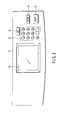
- the control panel 13 includes a liquid crystal display section 14 of a touch panel type, a ten-key 15 for inputting a numerical value, an all reset key 16, a copy key 17, and stop key 18.
- the liquid crystal display section 14 is capable of inputting information by a touch operation of fingers and displaying various kinds of information including inputted information. By touching the liquid crystal display section 14 with the fingers, it is possible to set a kind of image and conditions of image formation, to specify a size of the paper-sheet P which will be described below, and to input various codes for maintenance or service.
- a photosensitive drum 20 is rotatably disposed at a substantially central portion in the main body 1.
- an electrifier 21, a developer 22, a transcriber 23, an exfoliator 24, a cleaner 25, and a de-electrifier 26 are sequentially provided.
- the laser beam B emitted from the above laser unit 27 is applied onto the surface of the photosensitive drum 20 through a space between the electrifier 21 and the developer 22.
- a toner supply cartridge containing a developing agent, i.e., a toner is detachably attached to the developer 22. By the attachment of the toner supply cartridge, the developer 22 is supplied with the toner.
- a plurality of sheet containers i.e., sheet cassettes 30 are disposed on the bottom of the main body.
- sheet cassettes 30 a number of paper-sheets P of different sizes are contained.
- the paper-sheets P are taken out one by one from any one of the paper-sheet cassettes 30.
- pick-up rollers 31 are attached to the sheet cassettes, respectively.
- the paper-sheet P thus taken out is separated from the sheet cassette 30 by a separator 32, and sent to a pair of resist rollers 33.
- the resist rollers 33 feeds the paper-sheet P between the photosensitive drum 20 and the transcriber 23 at timing when the rotation of the photosensitive drum 20 is taken into account.
- the above electrifier 21 generates electrostatic charges on the surface of the photosensitive drum 20 by applying a high electric voltage to the photosensitive drum 20 to electrify it.
- the surface of the thus electrified photosensitive drum 20 is irradiated with the laser beam B emitted from the laser unit 27.
- the laser unit 27 primarily scans (linear scanning) the surface of the photosensitive drum 20 in one direction and simultaneously performs secondary scanning which repeats the primary scanning with the rotation of the photosensitive drum 20, thereby forming an electrostatic latent image corresponding to the image read from the original D on the surface of the photosensitive drum 20.
- the electrostatic latent image on the photosensitive drum 20 is developed by receiving the toner from the developer 22 to become a visible image.
- the visible image is transcribed to the paper-sheet P by the transcriber 23.
- the paper-sheet P on which the image is thus printed is peeled off from the photosensitive drum 20 by the exfoliator 24.
- the remaining developing agent is removed with the cleaner 25.
- the remaining electric charges are removed by a de-electrifier 28.
- the paper-sheet P peeled off from the photosensitive drum 20 is transferred to a fixing device 35 by a conveyer belt 34.
- the fixing device 35 fixes the transcribed image on the paper-sheet P by heating.
- the fixed paper-sheet is transferred to a discharge exit 37 by a sheet discharge roller 36, and then discharged through the discharge exit 37 onto a tray 38 which is outside the main body 1.
- a power switch 39 is disposed on the other side of the main body 1.
- FIG. 4 A whole control circuit of the apparatus is shown in FIG. 4.
- a control panel CPU 80 To a main CPU 50, there are connected a control panel CPU 80, a scanning CPU 90, and a print CPU 100.
- the main CPU 50 overall controls the control panel CPU 80, the scanning CPU 90 and the print CPU100, and includes a copy mode control section in accordance with the operation of the copy key 17, a printer mode control section in response to the image input into a net-interface 59 which will be described below, and a FAX (facsimile) mode control section in response to the image reception at a FAX receiving unit 79 described below.
- a ROM 51 for storing control programs
- a RAM 52 for storing data
- a page memory controller 56 controls the writing and the reading out of the image data in the page memory 57.
- an image data bus 61 there are interconnected the image processing section 55, the page memory controller 56, a page memory 57, the hand disk unit 58, the net-interface 59, and the FAX transmit-receive unit 60.
- the above net-interface 59 acts as an input section for a printer mode to which the image sent from external equipment is inputted.
- a communication network 110 such as LAN, an Internet is connected to the net-interface 59, and to the communication network 110 connected are external equipment, for example, a plurality of the personal computers 111.
- These personal computers 111 include a controller 112, a display 113, and an operation unit 114.
- the above FAX transmit-receive unit 60 is connected to a telephone line 120 and also acts as a reception section in a facsimile mode for receiving the image (image data) sent by facsimile through the telephone line 120.
- the scanning CPU 90 To the scanning CPU 90 connected are ROM 91 for storing control programs, a RAM 92 for storing data, a signal processing section 93 for processing the output of the above CCD 10 to supply it to the above image data bus 61, a CCD driver 94, a scanning motor driver 95, the exposure light 5, the automatic original feeder 40, a plurality of the original sensors 11, etc.
- the CCD driver 94 drives the above CCD 10.
- the scanning motor driver 95 drives a scanning motor 96 for driving the cartridge.
- the automatic original feeder 40 has an original sensor 43 for detecting the originals D and the sizes thereof.
- a reading section for reading optically the images of originals in the copy mode is composed of mainly the scanning CPU 90 and its peripheral constituents.
- a ROM 101 for storing a control program
- a RAM 102 for storing data
- a print engine 103 is composed of the above laser unit 27, a driving circuit thereof, etc.
- the paper-sheet conveyance unit 104 is composed of a sheet conveyance mechanism extending from the above sheet supply cassettes 30 to the tray 38, a driving circuit thereof, etc.
- the process unit 105 is composed of the above photosensitive drum 20, its peripherals, etc.
- the fixing unit 106 is composed of the above fixing device 35, its driving circuit, etc.
- a print section for printing the image processed in the above image processing section 55 on the sheets P in the sheet cassettes 30 is mainly composed of the print CPU 100 and its peripheral components.
- the above image processing section 55 has a function to divide a number of picture elements (normal picture elements) composing the image processed by the image processing section into a plurality of picture elements, for example 4 picture elements, respectively as well as the function to perform normal image processing with the read image in the above reading section, the inputted image into the net interface 59, and the received image in the above FAX transmit-receive unit 60.
- On-off operations of the laser unit 27 corresponding to the divided picture elements make the latent image corresponding to each divided picture element imaged on the photosensitive drum 20 by the primary scanning and the secondary scanning with the laser beam B from the laser unit 27.
- the edge portions of the image can be reproduced in details on the paper-sheet P.
- a pattern of the picture elements (normal picture elements) and a pattern of the divided picture elements of the image (electrostatic latent image) formed on the photosensitive drum 20 are shown in FIG. 5.
- a row Q1, Q2, ... Qn of the picture elements is formed along the direction of the primary scanning (linear scanning), and the row is sequentially arranged in the order of L1, L2, ... Ln along the direction of the secondary scanning.
- the patterns Q1, Q2, ... Qn of the picture elements are each composed of 4 divided picture elements Qa, Qb, Qc, Qd.
- all the divided picture elements Qa, Qb, Qc, Qd of the picture elements Q1, Q2 in the primary scanning L1, L2 are turn black (shown with oblique lines) by "on" of the laser beam B, as shown in FIG. 6.
- the divided picture elements Qb, Qc, Qd of the picture element Q3 in the primary scanning L1 When printing a circular image pattern, the divided picture elements Qb, Qc, Qd of the picture element Q3 in the primary scanning L1, the divided picture elements Qa, Qc, Qd of the picture element Q4 in the primary scanning L1, the divided picture elements Qa, Qb, Qd of the picture element Q3 in the primary scanning L2, and the divided picture elements Qa, Qb, Qc of the picture element Q4 in the primary scanning L2 are turn black (shown with oblique lines), respectively, by "on" of the laser beam B.
- the above picture element counter 53 counts, every mode such as a copy mode, a printer mode or a FAX mode, the number G of the divided picture elements which become the targets of the development (the divided picture elements which make the laser beam B turn on) among the divided picture elements forming the image processed in the image processing section 55.
- the above sheet number counter 54 counts, every mode such as the copy mode, the printer mode or the FAX mode, the number U of the paper-sheets P which are taken out of the sheet supply cassettes 30 and on which the image is printed. It is to be noted that since the paper-sheets P different in size are received in a plurality of sheet supply cassettes 30, respectively, there is provided in the main CPU 50 a converting section for converting the number U of the used paper-sheets P to the number Ux of the paper-sheets P having a reference size on the basis of a relation between the size of the paper-sheets and the beforehand designated reference size.
- the reference sizes plural sizes such as A3 size, LD size, A4 size, LT size are prepared.
- the reference number is A3
- the counted value U of the sheet number counter 54 is "2"
- the converted number Ux is "1" in the converting section.
- the counted value U of the sheet number counter 54 is "1"
- the converted number Ux is "2" in the converting section.
- the above RAM 52 functions as a first memory section and a second memory section.
- the first memory section stores, every reference size, the number Gs of the reference divided picture elements per unit area rate of the print area rate on the paper-sheet P, when an original of the reference size on which the image is depicted at a standard print area rate (also referred to as an occupied area rate of the image) Es, i.e., a reference chart is read by the present apparatus and printed on the paper-sheet P.
- the second memory section similarly stores, every reference size, a reference toner (developing agent) consumption fee Ms per unit area rate of the print area rate on the paper-sheet P, when the reference chart is read by the present apparatus and printed on the paper-sheet P.
- the print area rate is a value obtained by dividing the total area of the image, which is the target of the development, by the total area of the paper-sheet P. Accordingly, the print area rate is 0% in a case of a blank sheet on which nothing is printed as shown in FIG. 7; it is 50% in a case where the total area of the image, which is the target of the development, occupies half of the paper-sheet as shown in FIG. 8; and it is 100% in a case where the total area of the image, which is the target of the development, occupies the total area of the paper-sheet (the whole surface of the sheet is blackened) as shown in FIG. 9.
- the standard print area rate Es of the reference chart is, for example, 6%.
- the number of the divided picture elements forming 1% of the image on the paper-sheet P is the so-called number Gs of the reference divided picture elements per unit area rate.
- the number of normal picture elements forming the image which is the target of the development is 72M (mega)
- the main CPU 50 has, as principal functions, the following sections (1) to (16) in addition to the copy mode control section, the print mode control section, the FAX mode control section and the converting section mentioned above.
- the FAX transmit-receive unit 60 When the image (image data) transmitted by a facsimile through a telephone line 120 is received the FAX transmit-receive unit 60, the received image (image data) is also stored in the page memory 57.
- the image stored in the page memory 57 is image-processed in the image processing section 55.
- the processed image composed of a large number of picture elements (normal picture element) and each of the picture elements is divided into 4 pieces to become the divided picture elements.
- the electrostatic latent image corresponding to each divided picture element is imaged on the photosensitive drum 20 by the primary scanning and the secondary scanning on the photosensitive drum with the laser beam B emitted from the laser unit 27.
- the edge portions of the image can be reproduced in details on the paper-sheet.
- the electrostatic latent image imaged on the photosensitive drum 20 is developed to a visible image receiving a toner from the developer 22.
- the visible image is transcribed to the paper-sheet P with the transcriber 23.
- the paper-sheet P on which the image is printed is peeled off from the photosensitive drum 20 with the exfoliator 24, and is transferred to the fixing device 35 with the conveyer belt 34.
- the fixing device 35 fixes the transcribed image on the paper-sheet P by heating.
- the paper-sheet P fixed by the fixing device 35 is transferred to a discharge exit 37 by the sheet discharge roller 36 and discharged through the discharge exit 37 onto the tray 38 outside the main body 1.
- the number G of the divided picture elements (divided picture elements making the laser unit 27 perform an on-operation), which become the target of the development by the developer 22 among each divided picture element composing the image image-processed in the image processing section 55 is counted by the picture element counter 53 every mode (copy mode, printer mode or FAX mode).
- the number U of the paper-sheets P taken out of the sheet supply cassettes 30 for images to be printed thereon is counted by the sheet number counter 54 every mode.
- the counted number U of the used paper-sheets P is converted to the number Ux of the paper-sheets having the reference size on the basis of relation between the size of the used sheets and the beforehand designated reference size. For example, in a case where the reference number is A3 and when two paper-sheets P of the A4 size are used, the counted value U of the sheet number counter 54 is "2", but the converted number Ux is "1" in the converting section. On the contrary, in a case where the reference number is A4 and when 1 paper-sheet P of the A3 size is used, the counted value U of the sheet number counter 54 is "1", but the converted number Ux is "2" in the converting section.
- the print area rate E on the paper-sheet P is calculated every mode (copy mode, printer mode or FAX mode) by dividing the number G counted with the picture element counter 53 by the number Gs of the reference divided picture elements in the RAM 52.
- the normal picture elements are not counted, but the number G of the divided picture elements forming the normal picture elements is counted, and from the number G, the print area rate E is calculated, whereby a consumption state of the toner which is used for image print can be accurately detected.
- a relation between the calculated print area rate E and the actual print area rate is shown in FIG. 10, and both are approximately equal.
- the calculated print area rates E are sequentially accumulated, and the accumulated value is divided by the converted number Ux, whereby the average print area rate Ea is calculated every mode.
- the toner consumption fee M per sheet of the used paper-sheets P is calculated every mode by multiplying the calculated average print area rate Ea by the reference toner consumption fee Ms in the RAM 52.
- the number of the used paper-sheets P (the converted number Ux), the average print area rate Ea (%), the print area rate E (%) on the final sheet last calculated at present among print area rates E, and the toner consumption fee M ( ⁇ ) are displayed in the from of a list as a display screen of the toner consumption state on the liquid crystal display section 14.
- the display screen of the toner consumption state values of the respective modes are separately shown, and a total or an average of the respective modes are shown.
- the display screen of the toner consumption state there is a display pattern of a "transmit outward” button on the display screen of the toner consumption state.
- the display contents of the display screen of the toner consumption state can be transmitted to an external equipment (a personal computer 111, etc.) of a previously set address through the communication network 110. Accordingly, the toner consumption state can be collected and kept in the form of electronic data in an instrument at a manufacturer, etc.
- the present invention has the following functions (a) to (e) .
- the print area rate E, the average print area rate Ea, and the toner consumption fee M can be calculated by both the maintenance/inspection standard and the cartridge replacement standard.
- the calculated results by the maintenance/inspection standard and the calculated results by the cartridge replacement standard can be stored in the hard disk unit 58, and the display screen of the toner consumption state by the maintenance/inspection standard and the display screen of the toner consumption state by the cartridge replacement standard can be selectively displayed in the liquid crystal display section 14.
- the selection can be done also by inputting the code on the control panel 13.
- the description was given using the print of a monochromatic image as an example, but the process can be applied in the same manner to a print of a color image.
- the toner consumption state can be grasped every color.
Landscapes
- Physics & Mathematics (AREA)
- General Physics & Mathematics (AREA)
- Control Or Security For Electrophotography (AREA)
- Accessory Devices And Overall Control Thereof (AREA)
Abstract
Each picture element (Q1, Q2 ... Qn) of an image is divided into a plurality of picture elements (Qa, Qb, Qc, Qd), a latent image corresponding to the divided picture elements is formed on a photosensitive member (20), and the latent image is then developed with a developing agent to print it on a paper-sheet (P). Then, there is counted the number G of the divided picture elements which become targets of the development among the divided picture elements. <IMAGE>
Description
The present invention relates to an image forming
apparatus for reading an image depicted on an original
to print it on a sheet, and a method for controlling
the image forming apparatus.
An image forming apparatus such as a copy machine
optically reads an image on an original set on an
original table, forms an electrostatic latent image
corresponding to the read image on the surface of a
photosensitive drum, and develops (visualizes) the
electrostatic latent image with a developing agent
(toner) to print (transmit) it on a paper-sheet. The
formation of the electrostatic latent image on the
photosensitive drum is performed by scanning with a
laser beam radiated from a semiconductor laser, for
example, a laser diode.
The scanning with the laser beam is linearly
performed along the axial direction of the
photosensitive drum. The linear scanning is referred
to as primary scanning. The primary scanning is
repeatedly performed by rotation of the photosensitive
drum. Sequential movement of the primary scanning by
the rotation of the photosensitive drum is referred to
as secondary scanning.
The image read from the original is composed of a
number of picture elements. The primary scanning and
the secondary scanning are performed by "on" and "off"
the laser beam in accordance with these picture
elements.
The actual "on" and "off" of the laser beam are
performed in accordance with each picture element in
one case, or in accordance with plural divided
portions, for example, 4 divided portions of each
picture element in another case. By the "on" and "off"
in accordance with each divided picture element, edge
portions of the read images can be reproduced in detail
on the sheet. This is a so-called multi-segment
smoothing process.
On the other hand, the developing agent (toner)
for developing the electrostatic latent image on the
photosensitive drum is consumable, and it much be
replenished regularly or when needed. For this
replenishment, a user is burdened with a fee. The
consumption of the developing agent, which burden the
user with the fee, is an important concern to the user.
Conventionally, the consumption fee of the
developing agent is calculated on the basis of the
number of the used paper-sheets at a store or a rental
store of the apparatus. The thus calculated
consumption fee is demanded of the user.
The amount of the images to be printed on the
sheets varies, and it cannot be accurately grasped only
from the number of the used paper-sheets. Therefore,
there is possibility that an improper fee is demanded
of the user.
An object of the present invention is to provide a
reliable image forming apparatus and a method for
controlling the apparatus, wherein a consumption of
developing anent can be exactly grasped and thus a fee
burden to a user can be clarified.
An image forming apparatus of the present
invention divides each picture element of an image into
a plurality of picture elements, forms a latent image
corresponding to each of the divided picture elements
on a photosensitive member, and then develops the
latent image with a developing agent to print it on a
paper-sheet, and the image forming apparatus includes a
count section for counting the number of the divided
picture elements which become targets of development
among the divided picture elements.
This summary of the invention does not necessarily
describe all necessary features so that the invention
may also be a sub-combination of these described
features.
The invention can be more fully understood from
the following detailed description when taken in
conjunction with the accompanying drawings, in which:
In the following, one embodiment of the present
invention will be described referring to attached
drawings.
As shown in FIG. 1 and FIG. 2, a transparent
original table (glass plate) 2 for mounting an original
is disposed on an upper surface portion of a main body
1. An indicator 3 is disposed on one side of the
original table 2. A step between the indicator 3 and
the original table 2 functions as a reference position
for setting the original.
A plurality of original sensors 11 which will be
described later are provided on a lower surface side of
the original table 2. Presence/absence and a size of
originals D which are set on the original table 2 are
optically detected by these original sensors 11.
A carriage 4 is disposed under the original table
2, and an exposure lamp 5 is disposed on the carriage
4. The carriage 4 and the exposure lamp 5 constitute
an exposure means. The carriage 4 can move
(reciprocate) along the lower surface of the original
table 2. While the carriage 4 reciprocally moves along
the original table 2, the original D mounted on the
original table 2 is exposed to light by switching on
the exposure lamp 5.
A reflected light image from the original D can be
obtained through this exposure, and the image is
projected onto a CCD (charge coupled device) 10 via
reflection mirrors 6, 7, 8 and a lens block 9 for
changing magnification. The CCD 10 has a large number
of photoelectric transducer elements on an acceptance
region of the light, and image signals corresponding to
the image on the original D are outputted by linearly
scanning the acceptance region of the light and
repeating the linear scanning operation.
The image signals outputted from the CCD 10 are
amplified and converted into digital signals in a
signal processing section 93 which will be described
below, and the digital signals are properly processed
in an image processing section 55 which will be
described below, and then supplied to a laser unit 27.
The laser unit 27 emits a laser beam B in accordance
with the inputted signals.
A window 12 for reading the original is disposed
at a position adjacent to the indicator 3 of the
original table 2. The window 12 has a shape and a
size corresponding to a longitudinal length of the
indicator 3.
An automatic original feeder (ADF) 40 doubling as
an original table cover is disposed in an operable
manner over the original table 2, the indicator 3 and
the window 12. The automatic original feeder 40 having
a tray 41 for mounting the originals thereon feeds a
plurality of the originals set on the tray 41 one by
one to the window 12, passes them on the window 12, and
then discharges the passed originals onto a tray 42.
When the automatic original feeder 40 is operated, the
exposure lamp 5 emits the light at a position opposite
to the window 12, and with the light, the window 12 is
irradiated. The original D which is passing on the
window 12 is exposed through the window 12 to the light
with which the window 12 is irradiated.
A reflected light image from the original D can be
obtained by this exposure, and the image is then
projected onto the CCD 10 via the reflection mirrors 6,
7, 8 and the lens block 9 for changing magnification.
As an operating section for setting operation
conditions, a control panel 13 is disposed at a
position not overlapped with the automatic original
feeder 40 on the upper surface portion of the main body
1. As shown in FIG. 3, the control panel 13 includes a
liquid crystal display section 14 of a touch panel
type, a ten-key 15 for inputting a numerical value, an
all reset key 16, a copy key 17, and stop key 18. The
liquid crystal display section 14 is capable of
inputting information by a touch operation of fingers
and displaying various kinds of information including
inputted information. By touching the liquid crystal
display section 14 with the fingers, it is possible to
set a kind of image and conditions of image formation,
to specify a size of the paper-sheet P which will be
described below, and to input various codes for
maintenance or service.
On the other hand, a photosensitive drum 20 is
rotatably disposed at a substantially central portion
in the main body 1. Around the photosensitive drum 20,
there are sequentially provided an electrifier 21, a
developer 22, a transcriber 23, an exfoliator 24, a
cleaner 25, and a de-electrifier 26. Furthermore, the
laser beam B emitted from the above laser unit 27 is
applied onto the surface of the photosensitive drum 20
through a space between the electrifier 21 and the
developer 22.
A toner supply cartridge containing a developing
agent, i.e., a toner is detachably attached to the
developer 22. By the attachment of the toner supply
cartridge, the developer 22 is supplied with the toner.
A plurality of sheet containers, i.e., sheet
cassettes 30 are disposed on the bottom of the main
body. In the sheet cassettes 30, a number of paper-sheets
P of different sizes are contained. When a copy
key 17 is pushed, the paper-sheets P are taken out one
by one from any one of the paper-sheet cassettes 30.
To take out the paper-sheets, pick-uprollers 31 are
attached to the sheet cassettes, respectively. The
paper-sheet P thus taken out is separated from the
sheet cassette 30 by a separator 32, and sent to a pair
of resist rollers 33. The resist rollers 33 feeds the
paper-sheet P between the photosensitive drum 20 and
the transcriber 23 at timing when the rotation of the
photosensitive drum 20 is taken into account.
To take out the paper-sheets, pick-up
The above electrifier 21 generates electrostatic
charges on the surface of the photosensitive drum 20 by
applying a high electric voltage to the photosensitive
drum 20 to electrify it. The surface of the thus
electrified photosensitive drum 20 is irradiated with
the laser beam B emitted from the laser unit 27. The
laser unit 27 primarily scans (linear scanning) the
surface of the photosensitive drum 20 in one direction
and simultaneously performs secondary scanning which
repeats the primary scanning with the rotation of
the photosensitive drum 20, thereby forming an
electrostatic latent image corresponding to the image
read from the original D on the surface of the
photosensitive drum 20.
The electrostatic latent image on the
photosensitive drum 20 is developed by receiving the
toner from the developer 22 to become a visible image.
The visible image is transcribed to the paper-sheet P
by the transcriber 23. The paper-sheet P on which the
image is thus printed is peeled off from the
photosensitive drum 20 by the exfoliator 24. There
remain the developing agent and the electric charges on
the surface of the photosensitive drum 20 from which
the paper-sheet P has been peeled off. The remaining
developing agent is removed with the cleaner 25. The
remaining electric charges are removed by a de-electrifier
28.
The paper-sheet P peeled off from the
photosensitive drum 20 is transferred to a fixing
device 35 by a conveyer belt 34. The fixing device 35
fixes the transcribed image on the paper-sheet P by
heating. The fixed paper-sheet is transferred to a
discharge exit 37 by a sheet discharge roller 36, and
then discharged through the discharge exit 37 onto a
tray 38 which is outside the main body 1.
On the other side of the main body 1, a power
switch 39 is disposed.
A whole control circuit of the apparatus is shown
in FIG. 4.
To a main CPU 50, there are connected a control
panel CPU 80, a scanning CPU 90, and a print CPU 100.
The main CPU 50 overall controls the control panel CPU
80, the scanning CPU 90 and the print CPU100, and
includes a copy mode control section in accordance with
the operation of the copy key 17, a printer mode
control section in response to the image input into a
net-interface 59 which will be described below, and a
FAX (facsimile) mode control section in response to the
image reception at a FAX receiving unit 79 described
below.
Furthermore, to the main CPU 50 connected are a
ROM 51 for storing control programs, a RAM 52 for
storing data, a picture element counter 53, a sheet
number counter 54, an image processing section 55, a
page memory controller 56, a hard disk unit 58, the
net-interface 59, and a FAX transmit-receive unit 60.
The page memory controller 56 controls the writing and
the reading out of the image data in the page memory
57. Furthermore, by an image data bus 61, there are
interconnected the image processing section 55, the
page memory controller 56, a page memory 57, the hand
disk unit 58, the net-interface 59, and the FAX
transmit-receive unit 60.
The above net-interface 59 acts as an input
section for a printer mode to which the image sent from
external equipment is inputted. A communication
network 110 such as LAN, an Internet is connected to
the net-interface 59, and to the communication network
110 connected are external equipment, for example, a
plurality of the personal computers 111. These
personal computers 111 include a controller 112, a
display 113, and an operation unit 114.
The above FAX transmit-receive unit 60 is
connected to a telephone line 120 and also acts as a
reception section in a facsimile mode for receiving the
image (image data) sent by facsimile through the
telephone line 120.
To control panel CPU 80 connected are the above
liquid crystal display section 14, a ten-keys 15, an
all reset key 16, a copy key 17, and a stop key 18.
To the scanning CPU 90 connected are ROM 91 for
storing control programs, a RAM 92 for storing data, a
signal processing section 93 for processing the output
of the above CCD 10 to supply it to the above image
data bus 61, a CCD driver 94, a scanning motor driver
95, the exposure light 5, the automatic original feeder
40, a plurality of the original sensors 11, etc. The
CCD driver 94 drives the above CCD 10. The scanning
motor driver 95 drives a scanning motor 96 for driving
the cartridge. The automatic original feeder 40 has an
original sensor 43 for detecting the originals D and
the sizes thereof.
A reading section for reading optically the images
of originals in the copy mode is composed of mainly the
scanning CPU 90 and its peripheral constituents.
To the print CPU 100 connected are a ROM 101 for
storing a control program, a RAM 102 for storing data,
a print engine 103, a sheet conveyance unit 104, a
process unit 105, and a fixing unit 106. The print
engine 103 is composed of the above laser unit 27, a
driving circuit thereof, etc. The paper-sheet
conveyance unit 104 is composed of a sheet conveyance
mechanism extending from the above sheet supply
cassettes 30 to the tray 38, a driving circuit thereof,
etc. The process unit 105 is composed of the above
photosensitive drum 20, its peripherals, etc. The
fixing unit 106 is composed of the above fixing device
35, its driving circuit, etc.
A print section for printing the image processed
in the above image processing section 55 on the sheets
P in the sheet cassettes 30 is mainly composed of the
print CPU 100 and its peripheral components.
Now, the above image processing section 55 has a
function to divide a number of picture elements (normal
picture elements) composing the image processed by the
image processing section into a plurality of picture
elements, for example 4 picture elements, respectively
as well as the function to perform normal image
processing with the read image in the above reading
section, the inputted image into the net interface 59,
and the received image in the above FAX transmit-receive
unit 60. On-off operations of the laser unit
27 corresponding to the divided picture elements make
the latent image corresponding to each divided picture
element imaged on the photosensitive drum 20 by the
primary scanning and the secondary scanning with the
laser beam B from the laser unit 27. By means of the
on-off operations of the laser beam B corresponding to
each divided picture element, the edge portions of
the image can be reproduced in details on the paper-sheet
P.
A pattern of the picture elements (normal picture
elements) and a pattern of the divided picture elements
of the image (electrostatic latent image) formed on the
photosensitive drum 20 are shown in FIG. 5. A row Q1,
Q2, ... Qn of the picture elements is formed along the
direction of the primary scanning (linear scanning),
and the row is sequentially arranged in the order of
L1, L2, ... Ln along the direction of the secondary
scanning. The patterns Q1, Q2, ... Qn of the picture
elements are each composed of 4 divided picture
elements Qa, Qb, Qc, Qd.
For example, when printing a square image pattern,
all the divided picture elements Qa, Qb, Qc, Qd of the
picture elements Q1, Q2 in the primary scanning L1, L2
are turn black (shown with oblique lines) by "on" of
the laser beam B, as shown in FIG. 6. When printing a
circular image pattern, the divided picture elements
Qb, Qc, Qd of the picture element Q3 in the primary
scanning L1, the divided picture elements Qa, Qc, Qd of
the picture element Q4 in the primary scanning L1, the
divided picture elements Qa, Qb, Qd of the picture
element Q3 in the primary scanning L2, and the divided
picture elements Qa, Qb, Qc of the picture element Q4
in the primary scanning L2 are turn black (shown with
oblique lines), respectively, by "on" of the laser
beam B.
The above picture element counter 53 counts, every
mode such as a copy mode, a printer mode or a FAX mode,
the number G of the divided picture elements which
become the targets of the development (the divided
picture elements which make the laser beam B turn on)
among the divided picture elements forming the image
processed in the image processing section 55.
The above sheet number counter 54 counts, every
mode such as the copy mode, the printer mode or the FAX
mode, the number U of the paper-sheets P which are
taken out of the sheet supply cassettes 30 and on which
the image is printed. It is to be noted that since the
paper-sheets P different in size are received in a
plurality of sheet supply cassettes 30, respectively,
there is provided in the main CPU 50 a converting
section for converting the number U of the used paper-sheets
P to the number Ux of the paper-sheets P having
a reference size on the basis of a relation between the
size of the paper-sheets and the beforehand designated
reference size.
As the reference sizes, plural sizes such as A3
size, LD size, A4 size, LT size are prepared. In a
case where the reference number is A3, when 2 paper-sheets
P of the A4 size are used, the counted value U
of the sheet number counter 54 is "2", but the
converted number Ux is "1" in the converting section.
On the contrary, in a case where the reference number
is A4, when 1 paper-sheet P of the A3 size is used, the
counted value U of the sheet number counter 54 is "1",
but the converted number Ux is "2" in the converting
section.
The above RAM 52 functions as a first memory
section and a second memory section. The first memory
section stores, every reference size, the number Gs of
the reference divided picture elements per unit area
rate of the print area rate on the paper-sheet P, when
an original of the reference size on which the image is
depicted at a standard print area rate (also referred
to as an occupied area rate of the image) Es, i.e., a
reference chart is read by the present apparatus and
printed on the paper-sheet P. The second memory
section similarly stores, every reference size, a
reference toner (developing agent) consumption fee Ms
per unit area rate of the print area rate on the paper-sheet
P, when the reference chart is read by the
present apparatus and printed on the paper-sheet P.
The print area rate is a value obtained by
dividing the total area of the image, which is the
target of the development, by the total area of the
paper-sheet P. Accordingly, the print area rate is 0%
in a case of a blank sheet on which nothing is printed
as shown in FIG. 7; it is 50% in a case where the total
area of the image, which is the target of the
development, occupies half of the paper-sheet as shown
in FIG. 8; and it is 100% in a case where the total
area of the image, which is the target of the
development, occupies the total area of the paper-sheet
(the whole surface of the sheet is blackened) as shown
in FIG. 9.
The standard print area rate Es of the reference
chart is, for example, 6%. When the reference chart is
read by the present apparatus and printed on the paper-sheet
P, the number of the divided picture elements
forming 1% of the image on the paper-sheet P is the so-called
number Gs of the reference divided picture
elements per unit area rate.
For example, when the image whose entire surface
is blacken is printed on the A3 size paper-sheet, the
number of normal picture elements forming the image
which is the target of the development is 72M (mega),
and the number of the divided picture elements obtained
by dividing each normal picture element into 4 areas is
288M (mega) (= 72M × 4). Therefore, when the reference
chart having the reference size of A3 and the standard
print area rate Es of, e.g., 6% is read and printed,
the number of the normal picture elements forming the
image which is the target of the development is 4.32M
(= 72M × 0.06), and the number of the divided picture
elements is 17.28M (= 4.32M × 4).
The main CPU 50 has, as principal functions, the
following sections (1) to (16) in addition to the copy
mode control section, the print mode control section,
the FAX mode control section and the converting section
mentioned above.
Next, operations of the above constitution will be
described.
Once an original D is set on the original table 2,
the state of the setting is detected by each original
sensor 11 and the size of the original is also detected
by each of the original sensors 11. Then, the copy key
is pushed to read the image of the original D on
original table 2, and to store the read image (image
data) in the page memory 57.
When the image (image data) transmitted from the
personal computer 111 via the communication network 110
is inputted into the net interface 59, the inputted
image (image data) is stored in the page memory 57.
When the image (image data) transmitted by a
facsimile through a telephone line 120 is received the
FAX transmit-receive unit 60, the received image (image
data) is also stored in the page memory 57.
The image stored in the page memory 57 is image-processed
in the image processing section 55. The
processed image composed of a large number of picture
elements (normal picture element) and each of the
picture elements is divided into 4 pieces to become the
divided picture elements. With on-off operations of
the laser unit 27 corresponding to the divided picture
elements, the electrostatic latent image corresponding
to each divided picture element is imaged on the
photosensitive drum 20 by the primary scanning and the
secondary scanning on the photosensitive drum with the
laser beam B emitted from the laser unit 27. By means
of the on-off operations of the laser unit 27, the edge
portions of the image can be reproduced in details on
the paper-sheet.
The electrostatic latent image imaged on the
photosensitive drum 20 is developed to a visible image
receiving a toner from the developer 22. The visible
image is transcribed to the paper-sheet P with the
transcriber 23. The paper-sheet P on which the image
is printed is peeled off from the photosensitive drum
20 with the exfoliator 24, and is transferred to the
fixing device 35 with the conveyer belt 34. The fixing
device 35 fixes the transcribed image on the paper-sheet
P by heating. The paper-sheet P fixed by the
fixing device 35 is transferred to a discharge exit 37
by the sheet discharge roller 36 and discharged through
the discharge exit 37 onto the tray 38 outside the main
body 1.
At the time of printing the image, the number G of
the divided picture elements (divided picture elements
making the laser unit 27 perform an on-operation),
which become the target of the development by the
developer 22 among each divided picture element
composing the image image-processed in the image
processing section 55 is counted by the picture element
counter 53 every mode (copy mode, printer mode or FAX
mode).
At the same time, the number U of the paper-sheets
P taken out of the sheet supply cassettes 30 for images
to be printed thereon is counted by the sheet number
counter 54 every mode. The counted number U of the
used paper-sheets P is converted to the number Ux of
the paper-sheets having the reference size on the basis
of relation between the size of the used sheets and the
beforehand designated reference size. For example, in
a case where the reference number is A3 and when two
paper-sheets P of the A4 size are used, the counted
value U of the sheet number counter 54 is "2", but the
converted number Ux is "1" in the converting section.
On the contrary, in a case where the reference number
is A4 and when 1 paper-sheet P of the A3 size is used,
the counted value U of the sheet number counter 54 is
"1", but the converted number Ux is "2" in the
converting section.
Every one print of the sheet, the print area rate
E on the paper-sheet P is calculated every mode (copy
mode, printer mode or FAX mode) by dividing the number
G counted with the picture element counter 53 by the
number Gs of the reference divided picture elements in
the RAM 52.
As mentioned above, the normal picture elements
are not counted, but the number G of the divided
picture elements forming the normal picture elements is
counted, and from the number G, the print area rate E
is calculated, whereby a consumption state of the toner
which is used for image print can be accurately
detected. A relation between the calculated print area
rate E and the actual print area rate is shown in
FIG. 10, and both are approximately equal.
The calculated print area rates E are sequentially
accumulated, and the accumulated value is divided by
the converted number Ux, whereby the average print area
rate Ea is calculated every mode.
The toner consumption fee M per sheet of the used
paper-sheets P is calculated every mode by multiplying
the calculated average print area rate Ea by the
reference toner consumption fee Ms in the RAM 52.
Then, as shown in FIG. 11, the number of the used
paper-sheets P (the converted number Ux), the average
print area rate Ea (%), the print area rate E (%) on
the final sheet last calculated at present among print
area rates E, and the toner consumption fee M (¥) are
displayed in the from of a list as a display screen of
the toner consumption state on the liquid crystal
display section 14. In the display screen of the toner
consumption state, values of the respective modes are
separately shown, and a total or an average of the
respective modes are shown.
By displaying the display screen of the toner
consumption state, a maintenance man and a user can
accurately grasp the toner consumption state which
burden the user with the fee. Accordingly, the fee
which is the burden to the user can be clarified, which
can remarkably improve reliability.
It is to be noted that there is a display pattern
of a "print" button on the display screen of the toner
consumption state. By touching the "print" button, the
display contents of the display screen of the toner
consumption state are printed on the paper-sheet P. In
consequence, the toner consumption state can be
retained as a visible record on the paper-sheet.
Further, there is a display pattern of a "transmit
outward" button on the display screen of the toner
consumption state. By touching the "transmit outward"
button, the display contents of the display screen of
the toner consumption state can be transmitted to an
external equipment (a personal computer 111, etc.) of a
previously set address through the communication
network 110. Accordingly, the toner consumption state
can be collected and kept in the form of electronic
data in an instrument at a manufacturer, etc.
In addition to the functions described above,
the present invention has the following functions (a)
to (e) .
The reference size depends on a nation, a local region, a store, a lease store, etc. The number Gs of the reference divided picture elements is stored in the
By performing the count reset corresponding to the
input of the code at the time of maintenance/inspection
and the count reset automatically when replacing the
toner supply cartridge in the picture element counter
53, and also by performing the count reset corresponding
to the input of the code at the time of
maintenance/inspection and the count reset automatically
when replacing the toner supply cartridge in the
sheet number counter 53, the print area rate E,
the average print area rate Ea, and the toner
consumption fee M can be calculated by both the
maintenance/inspection standard and the cartridge
replacement standard. In this case, the calculated
results by the maintenance/inspection standard and the
calculated results by the cartridge replacement
standard can be stored in the hard disk unit 58, and
the display screen of the toner consumption state by
the maintenance/inspection standard and the display
screen of the toner consumption state by the cartridge
replacement standard can be selectively displayed in
the liquid crystal display section 14. The selection
can be done also by inputting the code on the control
panel 13.
Besides, in the above embodiment, the description
was given using the print of a monochromatic image as
an example, but the process can be applied in the same
manner to a print of a color image. In performing the
print of the color image, the toner consumption state
can be grasped every color.
Claims (20)
- An image forming apparatus which divides each picture element (Q1, Q2 ··· Qn) of an image into a plurality of picture elements (Qa, Qb, Qc, Qd), forms a latent image on a photosensitive member (20) in accordance with the divided picture elements (Qa, Qb, Qc, Qd), and then develops the latent image with a developing agent to print it on a paper-sheet (P), characterized by comprising:a counter (53) to count the number of the divided picture elements (Qa, Qb, Qc, Qd) which become targets of the development among the divided picture elements.
- An image forming apparatus characterized by comprising:an original table (2);a reading section (4, 5, 6, 7, 8, 9, 10, 90) which optically reads an image on an original set on the original table (2);a printing section (100, 103) which divides each picture element of the image read in the reading section (4, 5, 6, 7, 8, 9, 10, 90) into a plurality of picture elements (Qa, Qb, Qc, Qd), forms a latent image on a photosensitive member (20) in accordance with the divided picture elements, and then develops the latent image with a developing agent to print it on a paper-sheet (P); anda picture element counter (53) which counts, every paper-sheet (P), the number G of the divided picture elements (Qa, Qb, Qc, Qd) which become targets of the development among the divided picture elements.
- An apparatus of claim 2, characterized by further comprising:a first memory section (52) which stores the number Gs of reference divided picture elements per unit area rate of a print area rate on the paper-sheet (P), when the original of a reference size on which the image is depicted at a standard print area rate Es is read by the present apparatus and printed on the paper-sheet (P);a first calculating section (50) which calculates a print area rate E on the paper-sheet (P) by dividing the counted value G of the picture element counter (53) by the number Gs of the reference divided picture elements in the first memory section (52);a sheet number counter (54) to count the number U of the used paper-sheets (P);a second calculating section (50) which accumulates results E calculated in the first calculating section (50) and calculates an average print area rate Ea by dividing the accumulated value by the counted value U of the sheet number counter (54); andan informing section (14, 50) which informs the counted value U of the sheet number counter (54) and the average print area rate Ea calculated in the second calculating section (50), and informs the print area rate E last calculated at present among the print area rates E calculated in the first calculating section (50).
- An apparatus of claim 3, characterized by further comprising:an operating section (13);an adjusting section (50) which adjusts the number Gs of the reference divided picture elements in the first memory section (52) in accordance with the operation of the operating section (50); anda correcting section (50) which corrects, to 100%, a value near to 100% and larger than a set value E2, and corrects, to 0%, a value near to 0% and smaller than a set value E1 among the values of the print area rates E calculated in the first calculating section (50).
- An apparatus of claim 3, characterized by further comprising:a second memory (52) section which stores a reference developing agent consumption fee Ms per unit area rate of the print area rate on the paper-sheet (P), when the original of the reference size on which the image is depicted at the standard print area rate Es is read by the present apparatus and printed on the paper-sheet (P);a third calculating section (50) which calculates a developing agent consumption fee M per paper-sheet (P) by multiplying the average print area rate Ea calculated in the second calculating section (50) by the reference developing agent consumption fee Ms in the second memory section (52); andan informing section (14, 50) to inform the reference developing agent consumption fee Ms calculated in the third calculating section (50).
- An apparatus of claim 2, characterized by further comprising:a first memory section (52) which stores, every reference size, the number Gs of reference divided picture elements per unit area rate of a print area rate on the paper-sheet (P), when an original of a reference size on which an image is depicted at a standard print area rate Es is read by the present apparatus and printed on the paper-sheet (P);an operating section (13);a designating section (50) which designates the reference size in accordance with the operation of the operating section (13);a first selection section (50) which selects the number Gs of the reference divided picture elements corresponding to the reference size designated in the designating section among the numbers Gs of the reference divided picture elements in the first memory section (52);a first calculating section (50) which calculates a print area rate E on the paper-sheet (P) by dividing the counted value G of the picture element counter (53) by the number Gs of the reference divided picture elements selected in the first selection section (50);a sheet number counter (54) to count the number U of the used paper-sheets (P);a converting section (50) which converts the counted number U of the sheet number counter (54) to the number Ux of the paper-sheets (P) of the reference size designated in the designating section (50);a second calculating section (50) which accumulates the print area rates E calculated in the first calculating section (50), and calculates an average print area rate Ea dividing the accumulated value by the converted number Ux of the converting section (50); andan informing section (14, 50) which informs the converted number Ux of the converting section (50) and the average print area rate Ea calculated in the second calculating section (50), and informs the print area rate E last calculated at present among the print area rates E calculated in the first calculating section (50).
- An apparatus of claim 6, characterized by further comprising:an adjusting section (50) which adjusts the number Gs of the reference divided picture elements in the first memory section (52) in accordance with the operation of the operating section (13); anda correcting section which corrects, to 100%, a value near to 100% and larger than a set value E2, and corrects, to 100%, a value near to 0% and smaller than a set value E1 among the print area rates E calculated in the first calculating section (50).
- An apparatus of claim 6, characterized by further comprising:a second memory section (52) which stores, every reference size, the reference developing agent consumption fee Ms per unit area rate of the print area rate on the paper-sheet (P), when the original of the reference size on which the image is depicted at the standard print area rate Es is read by the present apparatus and printed on the paper-sheet (P);a second selection section (50) which selects the reference developing agent consumption fee Ms corresponding to the reference size designated in the designating section (50) among the reference developing agent consumption fees Ms in the second memory section (52);a third calculating section (50) which calculates a developing agent consumption fee M per paper-sheet (P) by multiplying the average print area rate Ea calculated in the second calculating section (50) by the reference developing agent consumption fee Ms selected in the second selection section (50); andan informing section (14, 50) which informs the reference developing agent consumption fee Ms calculated in the third calculating section (50).
- An apparatus of claim 2, characterized by further comprising:wherein:an input section (59) into which an image transmitted from an external device is inputted at a printer mode;the printing section (100, 103) which divides each picture element of the image read in the reading section and the image inputted into the input section into the plurality of picture elements (Qa, Qb, Qc, Qd), respectively, forms the latent image corresponding to the divided picture elements on a photosensitive member (20), and then develops the latent image with a developing agent to print it on the paper-sheet (P); andthe picture element counter (53) which counts, every paper-sheet (P) and every mode of the copy mode and the printer mode, the number G of the divided picture elements which become targets of the development among the divided picture elements.
- An apparatus of claim 9, characterized by further comprising:a first memory section (52) which stores, every reference size, the number Gs of reference divided picture elements per unit area rate of a print area rate on the paper-sheet (P), when an original of a reference size on which an image is depicted at a standard print area rate Es is read by the present apparatus and printed on the paper-sheet (P);an operating section (13);a designating section (50) which designates one of the reference sizes in accordance with the operation of the operating section (13);a first selection section (50) which selects the number Gs of the reference divided picture elements corresponding to the reference size designated in the designating section (50) among the numbers Gs of the reference divided picture elements in the first memory section (52);a first calculating section (50) which calculates, every mode, the print area rate E on the paper-sheet (P) by dividing the counted value G of the picture element counter (53) by the number Gs of the reference divided picture elements selected in the first selection section (50);a sheet number counter (54) to count the number U of the used paper-sheets (P) every mode;a converting section (50) which converts the counted number U of the sheet number counter (54) to the number Ux of the sheet (P) having the reference size designated in the designating section (50);a second calculating section (50) which accumulates print area rates E calculated in the first calculating section (50), and calculates an average print area rate Ea every mode by dividing the accumulated value by the converted number Ux of the converting section (50); andan informing section (14, 50) which informs the converted number Ux of the converting section (50) and the average print area rate Ea calculated in the second calculating section (50), and informs the print area rate E last calculated at present among the print area rates E calculated in the first calculating section (50).
- An apparatus of claim 9, characterized by further comprising:an adjusting section (50) which adjusts the number Gs of the reference divided picture elements in the first memory section (52) in accordance with the operation of the operating section (13); anda correcting section (50) which corrects, to 100%, a value near to 100% and larger than a set value E2, and corrects, to 0%, a value near to 0% and smaller than a set value E1 among the print area rates E calculated in the first calculating section (50).
- An apparatus of claim 9, characterized by further comprising:a second memory section (52) which stores, every reference size, the reference developing agent consumption fee Ms per unit area rate of the print area rate on the paper-sheet (P), when the original of the reference size on which the image is depicted at the standard print area rate Es is read by the present apparatus and printed on the paper-sheet (P);a second selection section (50) which selects the reference developing agent consumption fee Ms corresponding to the reference size designated in the designating section (50) among the reference developing agent consumption fees Ms in the second memory section (52);a third calculating section (50) which calculates, every mode, a developing agent consumption fee M per paper-sheet (P) by multiplying the average print area rate Ea calculated in the second calculating section (50) by the unit price Ms selected in the second selection section (50); andan informing section (14, 50) which informs the reference developing agent consumption fee M calculated in the third calculating section (50).
- An apparatus of claim 11, characterized in that the informing section (14, 50) comprises a liquid crystal display section (14) disposed on an external peripheral surface of a main body (1) of the apparatus, and a display control section (50) which displays informed contents as a display screen of a developing agent consumption state on the liquid crystal display section (14).
- An apparatus of claim 13, characterized by further comprising:a choice section (50) which chooses, by a manual operation, whether or not the display screen of the developing agent consumption state is displayed in the liquid crystal display section (14).
- An apparatus of claim 13, characterized by further comprising:a print control section (50) which prints the display contents of the display screen of the developing agent consumption state on the paper-sheet (P) as an image formation output of the apparatus.
- An apparatus of claim 13, characterized by further comprising:an outward transmission control section (50) which outward transmits the display contents of the display screen of the developing agent consumption state through communication networks (110).
- An apparatus of claim 10, characterized by further comprising:a reset section (50) which resets the counted value G of the picture element counter (53) and the counted value U of the sheet number counter (54) by a manual operation.
- An apparatus of claim 10, characterized by further comprising:a reset section (50) which automatically resets resetting the counted value G of the picture element counter (53) and the counted value U of the sheet number counter (54) when replacing a supply cartridge of the developing agent.
- An apparatus of claim 10, characterized by further comprising:a first reset section (50) which resets the counted value G of the picture element counter (53) and the counted value U of the sheet number counter (54) by a manual operation;a second reset section (50) which automatically resets resetting the counted value G of the picture element counter (53) and the counted value U of the sheet number counter (54) when replacing a supply cartridge of the developing agent; anda reset mode selection section (50) which selects one of a mode to perform the first reset section (50) and a mode to perform the second reset section (50) by a manual operation.
- A method which controls an image forming apparatus, comprising: dividing each picture element (Q1, Q2 ··· Qn) of an image into a plurality of picture elements (Qa, Qb, Qc, Qd), forming a latent image corresponding to the divided picture elements on a photosensitive member (20), and then developing the latent image with a developing agent to print it on a paper-sheet (P), the method characterized by further comprising:counting the number of the divided picture elements which become targets of the development among the divided picture elements.
Applications Claiming Priority (2)
| Application Number | Priority Date | Filing Date | Title |
|---|---|---|---|
| JP2002128874A JP2003323092A (en) | 2002-04-30 | 2002-04-30 | Image forming apparatus and control method thereof |
| JP2002128874 | 2002-04-30 |
Publications (1)
| Publication Number | Publication Date |
|---|---|
| EP1359472A2 true EP1359472A2 (en) | 2003-11-05 |
Family
ID=29208208
Family Applications (1)
| Application Number | Title | Priority Date | Filing Date |
|---|---|---|---|
| EP03009510A Withdrawn EP1359472A2 (en) | 2002-04-30 | 2003-04-28 | Image forming apparatus and method for controlling the apparatus |
Country Status (4)
| Country | Link |
|---|---|
| US (2) | US6813454B2 (en) |
| EP (1) | EP1359472A2 (en) |
| JP (1) | JP2003323092A (en) |
| CN (1) | CN1278193C (en) |
Families Citing this family (11)
| Publication number | Priority date | Publication date | Assignee | Title |
|---|---|---|---|---|
| US7580141B2 (en) | 2004-09-13 | 2009-08-25 | Kabushiki Kaisha Toshiba | Image forming apparatus |
| JP2007078887A (en) * | 2005-09-12 | 2007-03-29 | Sharp Corp | Image forming apparatus monitoring apparatus, monitoring apparatus control method, control program, and computer-readable recording medium |
| KR101301494B1 (en) * | 2006-12-05 | 2013-08-29 | 삼성전자주식회사 | Toner dispensing system and control method thereof |
| TWI330790B (en) * | 2007-01-26 | 2010-09-21 | Aetas Technology Inc | Method for analyzing a print/copy job |
| US7734209B2 (en) * | 2008-01-24 | 2010-06-08 | Sharp Laboratories Of America, Inc. | Imaging device with click count fragmentation |
| JP5380919B2 (en) | 2008-06-24 | 2014-01-08 | 日本電気株式会社 | Waveguide structure and printed wiring board |
| US8890761B2 (en) * | 2008-08-01 | 2014-11-18 | Nec Corporation | Structure, printed circuit board, antenna, transmission line to waveguide converter, array antenna, and electronic device |
| JP5326649B2 (en) * | 2009-02-24 | 2013-10-30 | 日本電気株式会社 | Antenna, array antenna, printed circuit board, and electronic device using the same |
| JP7030498B2 (en) * | 2017-12-13 | 2022-03-07 | キヤノン株式会社 | Image forming device, image forming method and program |
| CN110928153A (en) * | 2019-12-13 | 2020-03-27 | 上海旷沃科技有限公司 | Laser printer authority management system based on powdered ink metering |
| CN112819936B (en) * | 2021-01-29 | 2024-06-14 | 深圳锐沣科技有限公司 | Three-dimensional printing method, device, three-dimensional printing control device and storage medium |
Family Cites Families (4)
| Publication number | Priority date | Publication date | Assignee | Title |
|---|---|---|---|---|
| US5349377A (en) * | 1993-05-17 | 1994-09-20 | Xerox Corporation | Printer toner usage indicator with image weighted calculation |
| JP3431376B2 (en) * | 1995-10-28 | 2003-07-28 | 株式会社リコー | Image forming device |
| US6064838A (en) * | 1997-05-16 | 2000-05-16 | Minolta Co., Ltd. | Printing system that can identify printing cost beforehand |
| KR100374608B1 (en) * | 2001-01-06 | 2003-03-03 | 삼성전자주식회사 | Method for measuring consumtion volume of toner in printer and apparatus thereof |
-
2002
- 2002-04-30 JP JP2002128874A patent/JP2003323092A/en active Pending
-
2003
- 2003-04-28 EP EP03009510A patent/EP1359472A2/en not_active Withdrawn
- 2003-04-29 US US10/424,730 patent/US6813454B2/en not_active Expired - Fee Related
- 2003-04-29 CN CNB031306071A patent/CN1278193C/en not_active Expired - Fee Related
-
2004
- 2004-08-25 US US10/924,859 patent/US6954598B2/en not_active Expired - Fee Related
Also Published As
| Publication number | Publication date |
|---|---|
| US20050019051A1 (en) | 2005-01-27 |
| US20030202815A1 (en) | 2003-10-30 |
| US6954598B2 (en) | 2005-10-11 |
| CN1278193C (en) | 2006-10-04 |
| CN1456945A (en) | 2003-11-19 |
| US6813454B2 (en) | 2004-11-02 |
| JP2003323092A (en) | 2003-11-14 |
Similar Documents
| Publication | Publication Date | Title |
|---|---|---|
| JP4316484B2 (en) | Image forming apparatus, toner density control method, toner density control program and recording medium therefor | |
| JP4924729B2 (en) | Image forming apparatus | |
| US5459556A (en) | Toner consumption rate gauge for printers and copiers | |
| US4542985A (en) | Image formation apparatus | |
| US6813454B2 (en) | Method and image forming apparatus having a picture element counter | |
| US8031358B2 (en) | Image forming system including a plurality of image forming apparatuses | |
| JPH08146736A (en) | Image forming device | |
| US9037007B2 (en) | Image forming apparatus and toner remaining amount control method | |
| US6628904B2 (en) | Image forming apparatus | |
| JP4231239B2 (en) | Image forming apparatus and control method thereof | |
| JP4416813B2 (en) | Image forming apparatus and method for changing basic setting value thereof | |
| JP2002321843A (en) | Paper feeder | |
| JP6258670B2 (en) | Image forming apparatus and image forming system | |
| JPH10149065A (en) | Image forming device | |
| JP2006308854A (en) | Image forming apparatus | |
| JP2009003080A (en) | Electronics | |
| JP2000267520A (en) | Image forming apparatus, consumables replenishment instruction method for the apparatus, and computer-readable recording medium recording the program thereof | |
| JP2007008627A (en) | Image forming device | |
| JP2004086032A (en) | Image forming device | |
| JP2006084827A (en) | Digital copier | |
| JP2001278535A (en) | Image forming device | |
| JP2685743B2 (en) | Image forming device | |
| JP2026067440A (en) | Planned time calculation device, image forming apparatus, and planned time calculation method | |
| JP2659379B2 (en) | Image forming device | |
| JP2659378B2 (en) | Image forming device |
Legal Events
| Date | Code | Title | Description |
|---|---|---|---|
| PUAI | Public reference made under article 153(3) epc to a published international application that has entered the european phase |
Free format text: ORIGINAL CODE: 0009012 |
|
| 17P | Request for examination filed |
Effective date: 20030428 |
|
| AK | Designated contracting states |
Kind code of ref document: A2 Designated state(s): AT BE BG CH CY CZ DE DK EE ES FI FR GB GR HU IE IT LI LU MC NL PT RO SE SI SK TR |
|
| AX | Request for extension of the european patent |
Extension state: AL LT LV MK |
|
| STAA | Information on the status of an ep patent application or granted ep patent |
Free format text: STATUS: THE APPLICATION HAS BEEN WITHDRAWN |
|
| 18W | Application withdrawn |
Effective date: 20080305 |