EP1359446A2 - Optical switching fabric with an optical to electrical converter in the output plane - Google Patents
Optical switching fabric with an optical to electrical converter in the output plane Download PDFInfo
- Publication number
- EP1359446A2 EP1359446A2 EP02023229A EP02023229A EP1359446A2 EP 1359446 A2 EP1359446 A2 EP 1359446A2 EP 02023229 A EP02023229 A EP 02023229A EP 02023229 A EP02023229 A EP 02023229A EP 1359446 A2 EP1359446 A2 EP 1359446A2
- Authority
- EP
- European Patent Office
- Prior art keywords
- optical
- plane
- output
- input
- signals
- Prior art date
- Legal status (The legal status is an assumption and is not a legal conclusion. Google has not performed a legal analysis and makes no representation as to the accuracy of the status listed.)
- Withdrawn
Links
Images


Classifications
-
- G—PHYSICS
- G02—OPTICS
- G02B—OPTICAL ELEMENTS, SYSTEMS OR APPARATUS
- G02B6/00—Light guides; Structural details of arrangements comprising light guides and other optical elements, e.g. couplings
- G02B6/24—Coupling light guides
- G02B6/26—Optical coupling means
- G02B6/35—Optical coupling means having switching means
-
- G—PHYSICS
- G02—OPTICS
- G02B—OPTICAL ELEMENTS, SYSTEMS OR APPARATUS
- G02B6/00—Light guides; Structural details of arrangements comprising light guides and other optical elements, e.g. couplings
- G02B6/24—Coupling light guides
- G02B6/26—Optical coupling means
- G02B6/35—Optical coupling means having switching means
- G02B6/3598—Switching means directly located between an optoelectronic element and waveguides, including direct displacement of either the element or the waveguide, e.g. optical pulse generation
-
- H—ELECTRICITY
- H04—ELECTRIC COMMUNICATION TECHNIQUE
- H04Q—SELECTING
- H04Q11/00—Selecting arrangements for multiplex systems
- H04Q11/0001—Selecting arrangements for multiplex systems using optical switching
- H04Q11/0005—Switch and router aspects
-
- G—PHYSICS
- G02—OPTICS
- G02B—OPTICAL ELEMENTS, SYSTEMS OR APPARATUS
- G02B6/00—Light guides; Structural details of arrangements comprising light guides and other optical elements, e.g. couplings
- G02B6/24—Coupling light guides
- G02B6/26—Optical coupling means
- G02B6/35—Optical coupling means having switching means
- G02B6/351—Optical coupling means having switching means involving stationary waveguides with moving interposed optical elements
- G02B6/3512—Optical coupling means having switching means involving stationary waveguides with moving interposed optical elements the optical element being reflective, e.g. mirror
- G02B6/352—Optical coupling means having switching means involving stationary waveguides with moving interposed optical elements the optical element being reflective, e.g. mirror the reflective optical element having a shaped reflective surface, e.g. a reflective element comprising several reflective surfaces or facets that function together
-
- G—PHYSICS
- G02—OPTICS
- G02B—OPTICAL ELEMENTS, SYSTEMS OR APPARATUS
- G02B6/00—Light guides; Structural details of arrangements comprising light guides and other optical elements, e.g. couplings
- G02B6/24—Coupling light guides
- G02B6/26—Optical coupling means
- G02B6/35—Optical coupling means having switching means
- G02B6/351—Optical coupling means having switching means involving stationary waveguides with moving interposed optical elements
- G02B6/3524—Optical coupling means having switching means involving stationary waveguides with moving interposed optical elements the optical element being refractive
- G02B6/3526—Optical coupling means having switching means involving stationary waveguides with moving interposed optical elements the optical element being refractive the optical element being a lens
-
- G—PHYSICS
- G02—OPTICS
- G02B—OPTICAL ELEMENTS, SYSTEMS OR APPARATUS
- G02B6/00—Light guides; Structural details of arrangements comprising light guides and other optical elements, e.g. couplings
- G02B6/24—Coupling light guides
- G02B6/26—Optical coupling means
- G02B6/35—Optical coupling means having switching means
- G02B6/354—Switching arrangements, i.e. number of input/output ports and interconnection types
- G02B6/3554—3D constellations, i.e. with switching elements and switched beams located in a volume
- G02B6/3556—NxM switch, i.e. regular arrays of switches elements of matrix type constellation
-
- G—PHYSICS
- G02—OPTICS
- G02B—OPTICAL ELEMENTS, SYSTEMS OR APPARATUS
- G02B6/00—Light guides; Structural details of arrangements comprising light guides and other optical elements, e.g. couplings
- G02B6/24—Coupling light guides
- G02B6/26—Optical coupling means
- G02B6/35—Optical coupling means having switching means
- G02B6/354—Switching arrangements, i.e. number of input/output ports and interconnection types
- G02B6/3554—3D constellations, i.e. with switching elements and switched beams located in a volume
- G02B6/3558—1xN switch, i.e. one input and a selectable single output of N possible outputs
-
- G—PHYSICS
- G02—OPTICS
- G02B—OPTICAL ELEMENTS, SYSTEMS OR APPARATUS
- G02B6/00—Light guides; Structural details of arrangements comprising light guides and other optical elements, e.g. couplings
- G02B6/24—Coupling light guides
- G02B6/26—Optical coupling means
- G02B6/35—Optical coupling means having switching means
- G02B6/3564—Mechanical details of the actuation mechanism associated with the moving element or mounting mechanism details
- G02B6/3582—Housing means or package or arranging details of the switching elements, e.g. for thermal isolation
-
- H—ELECTRICITY
- H04—ELECTRIC COMMUNICATION TECHNIQUE
- H04Q—SELECTING
- H04Q11/00—Selecting arrangements for multiplex systems
- H04Q11/0001—Selecting arrangements for multiplex systems using optical switching
- H04Q11/0005—Switch and router aspects
- H04Q2011/0007—Construction
- H04Q2011/0026—Construction using free space propagation (e.g. lenses, mirrors)
- H04Q2011/0028—Construction using free space propagation (e.g. lenses, mirrors) using holograms
Definitions
- An all-optical switch is a "fan-out, fan-in” optical switch.
- "Fan-out, fan-in” optical switches have a plurality of single mode fibers as inputs and a plurality of single mode fibers as outputs.
- a 1xN optical switch that is associated with each input directs light to the Nx1 optical switch associated with the desired output.
- these "fan-out, fan-in” optical switches employ optics to perform the interconnection in free space.
- an optical switching fabric with at least one optical to electrical converter in the output plane has an input plane that receives at least one input signal.
- the input plane provides at least a first optical signal (e.g., a first set of optical signals).
- the switching mechanism has an output plane.
- the optical switching fabric also has an interconnection mechanism for receiving the first set of optical signals and directing each received optical signal to a predetermined location in the output plane.
- the output plane has at least one optical to electrical converter (e.g., an array of photo-detectors) for receiving the directed optical signals and responsive thereto for generating a set of corresponding electronic output signals.
- optical switching fabric 100 is suitable for selectively switching high-bandwidth signals (e.g., signals of the order of a gigabit per second or greater).
- the optical switching fabric 100 is also capable of high switching rates and is suitable for current applications that require reconfiguration times of the order of milliseconds.
- the output plane 120 includes at least one optical to electrical converter 124 (e.g., a photodetector).
- One aspect of the present invention is to provide an optical to electrical converter 124 in the output plane 120 instead of a single mode fiber.
- an optical to electrical converter 124 e.g., a photodetector
- an optical to electrical converter 124 in the output plane 120 has a larger target area and a greater angular tolerance for the light beams. Consequently, by utilizing optical to electrical converters 124 in the output plane 120, the number and complexity of the optical components required to steer light beams to the output plane 120, and specifically the optical to electrical converters in the output plane 120, are greatly reduced.
- the interconnection mechanism 130 can be any means for interconnecting a first set of input signals (e.g., P input signals) and a first set of output signals (e.g., P output signals). It is noted that the inputs 112 may be optical or electronic, and the outputs 128 are electronic, but may be converted into optical signals as described in greater detail hereinafter.
- the interconnection mechanism 130 performs the interconnection by optically steering the optical signals propagating in free space.
- the interconnection mechanism 130 includes an imaging system 150 and a beam steering plane 140.
- the output plane 120 includes one or more output elements.
- the output plane 120 can be, for example, a one-dimensional array of output elements or a two-dimensional (2D) array of output elements.
- the output plane 120 includes a plurality of optical to electrical converters 224 for converting the steered optical signals into corresponding electrical signals.
- each output element can include an optical to electrical converter.
- the optical to electrical converters 224 can be, for example, photodetectors.
- the imaging system 150 can include a plurality of optical elements 250 (e.g., lenses, curved mirrors, etc.) for focusing or collimating the light beams generated by the input plane 110.
- each optical signal leaving the input fiber or laser may have a corresponding optical element 250 for focusing the light beam onto a corresponding element in the beam steering plane 140.
- the imaging system 150 may include a plurality of lenses and/or mirrors that can be formed as part of an array. The purpose of the imaging system 150 is to image the input fiber or laser through the beamsteering element onto the desired photodetector in the output plane.
- the imaging system 150 may include other optical elements 154 (e.g., additional lenses, mirrors, optics, etc.) to aid alignment or reduce the size of the optical system 150. These optical elements 154 may be shared between all input and outputs. An example of these optical elements 154 is a folding mirror or an imaging lens for manipulation of optical signals provided by the input plane 110.
- the inputs to the optical switching fabric 100 can be optical or electronic. If the inputs are electronic, the inputs are first converted to optical signals by employing lasers. The optical signals are then directed to photodetectors in the output plane. The output signals from the optical to electrical converters 124 are by definition electronic. For applications that require optical outputs, lasers can be utilized to convert the electrical output signals into optical output signals.
- FIG. 2 illustrates an optical switching fabric 200 with electrical inputs 212 in accordance with a second embodiment of the present invention.
- each electronic signal is converted to a corresponding optical signal 214.
- an optical source 218 e.g., a light source
- each input element in the input plane can include a semiconductor laser for receiving the .electrical signal and responsive thereto for generating a corresponding light signal.
- the laser can use the electrical signal to modulate the optical output of the laser.
- the semiconductor laser can be, for example, a directly modulated vertical-cavity surface-emitting laser (VCSEL).
- VCSEL vertical-cavity surface-emitting laser
- the semiconductor lasers are arranged in a two-dimensional array (e.g., an N x M array of semiconductor lasers) so as to produce a two-dimensional array of optical signals that serve as the inputs to the interconnection mechanism 130.
- the output plane 120 is a two-dimensional (2D) array of photodetectors 224 (e.g., an N x M array of photodetectors).
- the beam steering plane 140 may be implemented with a two dimensional (2D) array of beamsteering elements 244 that directs light from each element 216 (e.g.,. optical source or optical fiber) in the input plane 110 to a predetermined element 226 in the output plane 120.
- the beamsteering element 244 may be a transmissive (e.g., a lens) or reflective (e.g., a mirror).
- Transmissive beamsteering elements are utilized in the switches illustrated in FIGS. 2 and 4 and described with reference thereto.
- Reflective beamsteering elements are utilized in the switch illustrated in FIG. 3 and described with reference thereto.
- the beamsteering plane 140 includes a beamsteering element for each optical input signal to steer the light from the input plane through space to arrive incident on a corresponding optical to electrical converter element in the output plane.
- beamsteering element 244 corresponds to light source 216 and steers the light generated by the light source 216 and directs the light to a corresponding optical to. electrical converter (e.g., photodetector 226) that is associated with a predetermined output channel.
- the beamsteering elements e.g., element 244) can steer the beam in multiple dimensions (e.g., in two dimensions).
- FIGS. 2-4 utilize input planes, beamsteering planes, and output planes that are configured as two-dimensional array of elements (e.g., N x M arrays).
- N x M arrays For the input planes, beamsteering planes, and output planes, either N or M can be 1 for some applications.
- one or more of the input planes, beamsteering planes, and output planes can be arranged as a one-dimensional array (e.g., 1 x M array or N x 1 array) of elements (e.g., optical sources, optical to electrical converters, etc.).
- an imaging system 150 can be provided between the input plane 310 and beamsteering plane 340, between the beamsteering plane 340 and the output plane 320, or between both sets of planes (310 and 340, 340 and 320).
- the imaging system 150 may be implemented with a microlens array and/or micromirrors.
- the micromirrors may be made non-flat to incorporate at least a portion of the imaging system 150 into the micromirror.
- the micromirrors may be manufactured with a silicon micro-machining process.
- the beamsteering plane 340 is provided that has a plurality of reflective beamsteering elements 344.
- the reflective beamsteering elements 344 that can be, for example, micro-mirrors that are manufactured by silicon micromachining.
- An output plane 320 receives the steering optical signals, converts the optical signals into corresponding electrical signals, and that provides the plurality of electrical output signals 328.
- FIG. 4 illustrates a optical switching fabric 400 with optical inputs that employs phase hologram beamsteering elements 444 in accordance with a fourth embodiment of the present invention.
- the inputs to the optical switching fabric 400 are optical signals 412. These optical signals 412 can, for example, arrive on a plurality of optical fibers 414.
- the optical fibers 414 can be arranged in a two-dimensional array, so as to produce a two-dimensional array 416 of optical signals that serve as the inputs to the interconnection mechanism 130.
- each input optical fiber 414 carries a single wavelength.
- a beamsteering plane 440 is provided that has a plurality of beamsteering elements 444.
- the beamsteering elements 444 can be transmissive beamsteering elements (as shown in FIG. 4) or reflective beamsteering elements.
- the optical switching fabric of the present invention has a higher capacity than conventional OEO switches (e.g., scalable to higher capacities). Furthermore, the switch of the present invention is more compact than OEO switches and consumes less power.
- the switch of the present invention is simpler and less expensive than conventional optical switches for the following reasons.
- the optical switching fabric of the present invention employs an array of optical to electrical converters (e.g., photodetectors) instead of an array of fibers utilized by the prior art.
- photodetectors are insensitive to a first order to the incidence angle of the light the photodetectors detect.
- single mode fibers have a small numerical aperture.
- a photodetector's active area may be larger than the core of a single mode fiber. For both these reasons, alignment tolerances are relaxed, and the required optical system is simplified for the optical switching fabric of the present invention.
- the optical system required for the switch of the present invention has fewer elements (e.g., only one beamsteering array), has relaxed alignment tolerances (e.g., relaxed angular tolerances), and requires simpler control.
- the prior art optical switches typically have the need for very sophisticated closed-loop control to achieve and maintain the required optical alignment
- the switch of the present invention needs either much simpler control or no control at all. Since sophisticated closed-loop control is expensive and raises reliability issues for prior art switches, the switch of the present invention obviates these expenses and reliability issues by employing optical to electrical converters in the output plane that require a simpler optical system and related control.
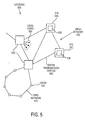
- the network 500 also includes a ring network 515, in which the nodes are a particular type of OXC called an optical add-drop multiplexer (OADM) 520.
- OADM optical add-drop multiplexer
- An OADM is an OXC connected to only two other nodes.
- the OADM 520 performs the same function as an OXC.
Landscapes
- Physics & Mathematics (AREA)
- General Physics & Mathematics (AREA)
- Optics & Photonics (AREA)
- Engineering & Computer Science (AREA)
- Computer Networks & Wireless Communication (AREA)
- Optical Modulation, Optical Deflection, Nonlinear Optics, Optical Demodulation, Optical Logic Elements (AREA)
- Optical Couplings Of Light Guides (AREA)
- Mechanical Light Control Or Optical Switches (AREA)
Abstract
Description
Claims (10)
- An optical switch (100) comprising:wherein the output plane (120) includes at least one optical to electrical converter (124) for receiving the directed first optical signal and responsive thereto for generating a corresponding electronic output signal.a) an input plane (110) for providing at least a first optical signal;b) an output plane (120); andc) an interconnection mechanism (130) for receiving the first optical signal and directing the first optical signal to a predetermined location in the output plane;
- The optical switch of claim 1 wherein the interconnection mechanism further includes:a beamsteering plane (140) having at least one beamsteering element for steering the first optical signal from the input plane through space to arrive incident on the optical to electrical converter in the output plane.
- The optical switch of claim 2 further comprising:an imaging system (150) for imaging the first optical signal through the beamsteering element onto the optical to electrical converter in the output plane.
- The optical switch of one of the preceding claims wherein the input plane includes one of a one-dimensional array of lasers and a two-dimensional array of lasers.
- The optical switch of claim 4 wherein the input plane includes one of a one-dimensional array of vertical-cavity surface-emitting lasers (VCSELs) and a two dimensional array of vertical-cavity surface-emitting lasers (VCSELs).
- The optical switch of one of the preceding claims wherein the input plane is coupled to one of a one-dimensional array of optical fibers and a two-dimensional array of optical fibers.
- The optical switch of one of the preceding claims wherein the output plane includes one of a one-dimensional array of photodetectors and a two dimensional array of photodetectors.
- The optical switch of one of the preceding claims wherein the input plane receives a plurality of inputs (112) that includes one of a plurality of electrical input signals and a plurality of optical input signals.
- The optical switch of one of the preceding claims wherein the output plane generates a plurality of output signals (128) that includes a plurality of electrical output signals.
- The optical switch of claim 2 and one of the preceding claims wherein the beamsteering element is a transmissive beamsteering element.
Applications Claiming Priority (2)
| Application Number | Priority Date | Filing Date | Title |
|---|---|---|---|
| US104193 | 2002-03-21 | ||
| US10/104,193 US7174065B2 (en) | 2002-03-21 | 2002-03-21 | Optical switching fabric with an optical to electrical converter in the output plane |
Publications (2)
| Publication Number | Publication Date |
|---|---|
| EP1359446A2 true EP1359446A2 (en) | 2003-11-05 |
| EP1359446A3 EP1359446A3 (en) | 2004-10-13 |
Family
ID=28040529
Family Applications (1)
| Application Number | Title | Priority Date | Filing Date |
|---|---|---|---|
| EP02023229A Withdrawn EP1359446A3 (en) | 2002-03-21 | 2002-10-16 | Optical switching fabric with an optical to electrical converter in the output plane |
Country Status (2)
| Country | Link |
|---|---|
| US (1) | US7174065B2 (en) |
| EP (1) | EP1359446A3 (en) |
Cited By (1)
| Publication number | Priority date | Publication date | Assignee | Title |
|---|---|---|---|---|
| CN110366057A (en) * | 2018-04-09 | 2019-10-22 | 中兴通讯股份有限公司 | Optical cross-connect equipment control method, device, optical transmission equipment and storage medium |
Families Citing this family (7)
| Publication number | Priority date | Publication date | Assignee | Title |
|---|---|---|---|---|
| US6801679B2 (en) * | 2001-11-23 | 2004-10-05 | Seungug Koh | Multifunctional intelligent optical modules based on planar lightwave circuits |
| US8909007B2 (en) | 2010-10-29 | 2014-12-09 | Hewlett-Packard Development Company, L.P. | Circuit switchable optical device |
| CN102075428B (en) * | 2011-01-20 | 2012-11-14 | 中国电信股份有限公司 | Integrated routing setting method and device |
| GB201104235D0 (en) | 2011-03-14 | 2011-04-27 | Cambridge Entpr Ltd | Optical beam routing apparatus and methods |
| GB201620744D0 (en) | 2016-12-06 | 2017-01-18 | Roadmap Systems Ltd | Multimode fibre optical switching systems |
| CN108681059B (en) * | 2018-05-07 | 2023-12-08 | 中国人民解放军陆军工程大学 | Sub-microsecond two-dimensional optical observation device |
| US11454769B2 (en) * | 2020-10-02 | 2022-09-27 | X Development Llc | Determining pointing accuracy using optical fiber bundle |
Family Cites Families (15)
| Publication number | Priority date | Publication date | Assignee | Title |
|---|---|---|---|---|
| US5239598A (en) * | 1987-11-20 | 1993-08-24 | The Secretary Of State For Defence In Her Britannic Majesty's Government Of The United Kingdom Of Great Britain And Northern Ireland | Electro-optic waveguide device |
| US5512907A (en) * | 1994-10-03 | 1996-04-30 | General Electric Company | Optical beamsteering system |
| US5798580A (en) | 1996-10-09 | 1998-08-25 | Morozov; Valentin | Contention free global interconnection |
| US6167170A (en) * | 1997-06-19 | 2000-12-26 | Pirelli Cavi E Sistemi S.P.A. | Optical switching device |
| EP1542413B1 (en) | 1998-03-05 | 2006-10-25 | Nippon Telegraph & Telephone Corporation | Optical interconnections in an ATM switch |
| US6320993B1 (en) | 1998-06-05 | 2001-11-20 | Astarte Fiber Networks, Inc. | Optical switch pathway configuration using control signals |
| US6335992B1 (en) | 2000-02-15 | 2002-01-01 | Tellium, Inc. | Scalable optical cross-connect system and method transmitter/receiver protection |
| US6501866B2 (en) | 2000-02-25 | 2002-12-31 | Mahi Networks. Inc. | Method and apparatus for cross-connecting optical transmission signals |
| WO2001090823A1 (en) | 2000-05-22 | 2001-11-29 | Intelligent Pixels, Inc. | Electro-optical component having a reconfigurable phase state |
| US6344912B1 (en) | 2000-05-26 | 2002-02-05 | Versatile Optical Networks | Hybrid and scalable opto-electronic processing in a wavelength-division multiplexed system |
| WO2001096924A1 (en) | 2000-06-14 | 2001-12-20 | Versatile Optical Networks, Inc. | Actively-controllable optical switches based on optical position sensing and applications in optical switching arrays |
| EP1370894B1 (en) | 2001-01-17 | 2013-03-13 | The Whitaker LLC | Optical cross connect |
| US6539142B2 (en) * | 2001-06-01 | 2003-03-25 | Agilent Technologies, Inc. | System and method for actively aligning mirrors in an optical switch |
| US7509048B2 (en) * | 2001-07-20 | 2009-03-24 | Essex Corporation | Method and apparatus for optical signal processing using an optical tapped delay line |
| US6760502B2 (en) * | 2001-12-04 | 2004-07-06 | Lucent Technologies Inc. | Power monitoring arrangement for optical cross-connect systems |
-
2002
- 2002-03-21 US US10/104,193 patent/US7174065B2/en not_active Expired - Fee Related
- 2002-10-16 EP EP02023229A patent/EP1359446A3/en not_active Withdrawn
Cited By (2)
| Publication number | Priority date | Publication date | Assignee | Title |
|---|---|---|---|---|
| CN110366057A (en) * | 2018-04-09 | 2019-10-22 | 中兴通讯股份有限公司 | Optical cross-connect equipment control method, device, optical transmission equipment and storage medium |
| CN110366057B (en) * | 2018-04-09 | 2021-12-31 | 中兴通讯股份有限公司 | Optical cross device control method, apparatus, optical transmission device and storage medium |
Also Published As
| Publication number | Publication date |
|---|---|
| US20030179983A1 (en) | 2003-09-25 |
| EP1359446A3 (en) | 2004-10-13 |
| US7174065B2 (en) | 2007-02-06 |
Similar Documents
| Publication | Publication Date | Title |
|---|---|---|
| US6657770B2 (en) | Programmable optical multiplexer/demultiplexer | |
| CA2392704C (en) | System and method of optical switching | |
| US7302134B2 (en) | Wavelength selective switch with a 2D arrangement of optical ports | |
| US6614953B2 (en) | Modular all-optical cross-connect | |
| US6539142B2 (en) | System and method for actively aligning mirrors in an optical switch | |
| US20090297097A1 (en) | Reconfigurable optical switch | |
| CA2466672C (en) | Optical crossbar switch | |
| US7599619B2 (en) | Wavelength division multiplexed optical communication system having a reconfigurable optical switch and a tunable backup laser transmitter | |
| US6819821B2 (en) | Optical switch with a geometry based on perpendicularly-oriented planar lightwave circuit switches | |
| US7174065B2 (en) | Optical switching fabric with an optical to electrical converter in the output plane | |
| US10110313B2 (en) | Optical switching apparatus, optical cross-connect node, and optical signal switching method | |
| JP4865365B2 (en) | Wavelength selective switch and integrated wavelength demultiplexer using stacked planar waveguide circuits | |
| US7231147B1 (en) | System and method of wavelength add/drop multiplexing having client configurability | |
| EP4460034A1 (en) | Extendable optical circuit switch architecture | |
| US7031611B2 (en) | Optical routers using angular position amplification modules | |
| Kozhevnikov et al. | Integrated array of 1× N optical switches for wavelength-independent and WDM applications | |
| Marom | Enabling Devices using MicroElectroMechanical System (MEMS) Technology for Optical Networking |
Legal Events
| Date | Code | Title | Description |
|---|---|---|---|
| PUAI | Public reference made under article 153(3) epc to a published international application that has entered the european phase |
Free format text: ORIGINAL CODE: 0009012 |
|
| AK | Designated contracting states |
Kind code of ref document: A2 Designated state(s): AT BE BG CH CY CZ DE DK EE ES FI FR GB GR IE IT LI LU MC NL PT SE SK TR |
|
| AX | Request for extension of the european patent |
Extension state: AL LT LV MK RO SI |
|
| PUAL | Search report despatched |
Free format text: ORIGINAL CODE: 0009013 |
|
| AK | Designated contracting states |
Kind code of ref document: A3 Designated state(s): AT BE BG CH CY CZ DE DK EE ES FI FR GB GR IE IT LI LU MC NL PT SE SK TR |
|
| AX | Request for extension of the european patent |
Extension state: AL LT LV MK RO SI |
|
| 17P | Request for examination filed |
Effective date: 20050315 |
|
| 17Q | First examination report despatched |
Effective date: 20050419 |
|
| AKX | Designation fees paid |
Designated state(s): DE FR GB |
|
| STAA | Information on the status of an ep patent application or granted ep patent |
Free format text: STATUS: THE APPLICATION IS DEEMED TO BE WITHDRAWN |
|
| 18D | Application deemed to be withdrawn |
Effective date: 20050830 |