EP1359356A1 - Ball lock cable tie - Google Patents
Ball lock cable tie Download PDFInfo
- Publication number
- EP1359356A1 EP1359356A1 EP03252771A EP03252771A EP1359356A1 EP 1359356 A1 EP1359356 A1 EP 1359356A1 EP 03252771 A EP03252771 A EP 03252771A EP 03252771 A EP03252771 A EP 03252771A EP 1359356 A1 EP1359356 A1 EP 1359356A1
- Authority
- EP
- European Patent Office
- Prior art keywords
- strap
- aperture
- head
- roller means
- cable tie
- Prior art date
- Legal status (The legal status is an assumption and is not a legal conclusion. Google has not performed a legal analysis and makes no representation as to the accuracy of the status listed.)
- Granted
Links
Images




Classifications
-
- H—ELECTRICITY
- H02—GENERATION; CONVERSION OR DISTRIBUTION OF ELECTRIC POWER
- H02G—INSTALLATION OF ELECTRIC CABLES OR LINES, OR OF COMBINED OPTICAL AND ELECTRIC CABLES OR LINES
- H02G3/00—Installations of electric cables or lines or protective tubing therefor in or on buildings, equivalent structures or vehicles
- H02G3/24—Installation of lines or cables on walls, ceilings or floors by means of insulators
-
- F—MECHANICAL ENGINEERING; LIGHTING; HEATING; WEAPONS; BLASTING
- F16—ENGINEERING ELEMENTS AND UNITS; GENERAL MEASURES FOR PRODUCING AND MAINTAINING EFFECTIVE FUNCTIONING OF MACHINES OR INSTALLATIONS; THERMAL INSULATION IN GENERAL
- F16L—PIPES; JOINTS OR FITTINGS FOR PIPES; SUPPORTS FOR PIPES, CABLES OR PROTECTIVE TUBING; MEANS FOR THERMAL INSULATION IN GENERAL
- F16L3/00—Supports for pipes, cables or protective tubing, e.g. hangers, holders, clamps, cleats, clips, brackets
- F16L3/22—Supports for pipes, cables or protective tubing, e.g. hangers, holders, clamps, cleats, clips, brackets specially adapted for supporting a number of parallel pipes at intervals
- F16L3/23—Supports for pipes, cables or protective tubing, e.g. hangers, holders, clamps, cleats, clips, brackets specially adapted for supporting a number of parallel pipes at intervals for a bundle of pipes or a plurality of pipes placed side by side in contact with each other
- F16L3/233—Supports for pipes, cables or protective tubing, e.g. hangers, holders, clamps, cleats, clips, brackets specially adapted for supporting a number of parallel pipes at intervals for a bundle of pipes or a plurality of pipes placed side by side in contact with each other by means of a flexible band
-
- B—PERFORMING OPERATIONS; TRANSPORTING
- B65—CONVEYING; PACKING; STORING; HANDLING THIN OR FILAMENTARY MATERIAL
- B65D—CONTAINERS FOR STORAGE OR TRANSPORT OF ARTICLES OR MATERIALS, e.g. BAGS, BARRELS, BOTTLES, BOXES, CANS, CARTONS, CRATES, DRUMS, JARS, TANKS, HOPPERS, FORWARDING CONTAINERS; ACCESSORIES, CLOSURES, OR FITTINGS THEREFOR; PACKAGING ELEMENTS; PACKAGES
- B65D63/00—Flexible elongated elements, e.g. straps, for bundling or supporting articles
- B65D63/02—Metallic straps, tapes, or bands; Joints between ends thereof
- B65D63/06—Joints produced by application of separate securing members, e.g. by deformation thereof
- B65D63/08—Joints using buckles, wedges, or like locking members attached to the ends of the elements
-
- Y—GENERAL TAGGING OF NEW TECHNOLOGICAL DEVELOPMENTS; GENERAL TAGGING OF CROSS-SECTIONAL TECHNOLOGIES SPANNING OVER SEVERAL SECTIONS OF THE IPC; TECHNICAL SUBJECTS COVERED BY FORMER USPC CROSS-REFERENCE ART COLLECTIONS [XRACs] AND DIGESTS
- Y10—TECHNICAL SUBJECTS COVERED BY FORMER USPC
- Y10T—TECHNICAL SUBJECTS COVERED BY FORMER US CLASSIFICATION
- Y10T24/00—Buckles, buttons, clasps, etc.
- Y10T24/14—Bale and package ties, hose clamps
- Y10T24/1457—Metal bands
- Y10T24/1459—Separate connections
-
- Y—GENERAL TAGGING OF NEW TECHNOLOGICAL DEVELOPMENTS; GENERAL TAGGING OF CROSS-SECTIONAL TECHNOLOGIES SPANNING OVER SEVERAL SECTIONS OF THE IPC; TECHNICAL SUBJECTS COVERED BY FORMER USPC CROSS-REFERENCE ART COLLECTIONS [XRACs] AND DIGESTS
- Y10—TECHNICAL SUBJECTS COVERED BY FORMER USPC
- Y10T—TECHNICAL SUBJECTS COVERED BY FORMER US CLASSIFICATION
- Y10T24/00—Buckles, buttons, clasps, etc.
- Y10T24/14—Bale and package ties, hose clamps
- Y10T24/1457—Metal bands
- Y10T24/1459—Separate connections
- Y10T24/1473—Wedging parts
-
- Y—GENERAL TAGGING OF NEW TECHNOLOGICAL DEVELOPMENTS; GENERAL TAGGING OF CROSS-SECTIONAL TECHNOLOGIES SPANNING OVER SEVERAL SECTIONS OF THE IPC; TECHNICAL SUBJECTS COVERED BY FORMER USPC CROSS-REFERENCE ART COLLECTIONS [XRACs] AND DIGESTS
- Y10—TECHNICAL SUBJECTS COVERED BY FORMER USPC
- Y10T—TECHNICAL SUBJECTS COVERED BY FORMER US CLASSIFICATION
- Y10T24/00—Buckles, buttons, clasps, etc.
- Y10T24/14—Bale and package ties, hose clamps
- Y10T24/1457—Metal bands
- Y10T24/148—End-to-end integral band end connection
Definitions
- the present invention is directed to a cable tie, and more particularly, to a tie that utilises a roller means as the locking mechanism.
- a cable tie comprising an elongated metallic strap having a first end and a second end opposite the first end and a metallic locking head secured to the first end of the strap for receiving the second end of the strap, the head comprising a strap entry face, a strap exit face, and a strap-receiving aperture extending therebetween, the head further comprising a floor and a roof which diverge in the direction of the exit face and metallic roller means for lockingly engaging the strap, the head comprising retention means disposed adjacent the exit face for captively holding the roller means within the head; the roller means being movable between a threading position wherein the roller means is disposed adjacent the exit face and the retention means, and a locking position wherein the roller means is closer to the entry face; wherein the first end of the strap comprises an aperture for co-operating with said roller means for said locking engagement.
- a method of locking a strap portion within a locking head of a cable tie having portions defining a passage, wherein a roller means is disposed in said passage, the method comprising forming said passage-defining portions such that threading of said strap portion beside said roller means in a first direction results in positive engagement between the strap portion and the roller means, regardless of the orientation of the locking head, wherein movement of the threaded strap portion in a second direction opposite the first direction draws the roller means in said second direction, and providing a locking formation in one of said passage-defining portions, said locking formation being disposed such that the roller means becomes engaged with said locking formation as a result of said drawing of the roller means in said second direction, whereby said strap portion becomes locked.
- the cable tie is made of stainless steel.
- the strap is coated.
- the roller means is a ball.
- the aperture is substantially circular.
- the diameter of the ball is equal to or greater than the diameter of the aperture.
- the retention means is a finger extending from the roof adjacent the exit face.
- the width of the strap is at least twice the width of the aperture.
- the illustrated embodiments of the invention are directed to a three-piece cable tie that utilises a roller means as the locking mechanism.
- Cable tie 22 for bundling a plurality of elongate objects, such as wires 20, and for holding objects together is generally indicated in FIG 1 by reference numeral 22.
- Cable tie 22 includes a locking head 24 secured to a first end 26 of an elongate strap 28 for receiving a second end 30 of the strap 28, and roller means in the form of a ball or sphere 32, best shown in FIGS 6-10, for retaining the strap 28 within the locking head 24.
- the ball, head and strap are formed of stainless steel to allow the strap to be used over a wide temperature range and to give the cable tie high strength and excellent resistance to corrosion. Additionally, or alternatively as known in the art, the strap 28 may be coated.
- the cable tie of the present invention is formed by assembling a locking head 24, a strap 28 and a hooked portion 34 formed integral with the strap 28 as shown in FIG 3.
- the strap 28 has an aperture 36.
- the width of the strap 28 is at least twice the width of aperture 36.
- the width of the strap 28 is 0.8cm (0.312 inches) and the width of the aperture 36 is 0.32cm (0.125 inches).
- locking head 24 comprises a roof 38, a ceiling 40, and a bottom wall 42 with the ceiling 40 and bottom wall 42 joined by a pair of sidewalls 44.
- the bottom wall 42 may include an aperture 46.
- the aperture 46 is substantially circular.
- the locking head 24 includes a strap entry face 48, a strap exit face 50, and a strap-receiving aperture 52 extending therebetween.
- the roof 38 and floor 54 diverge in the direction of the exit face 50.
- the ball 32 has a textured or roughened surface to increase its coefficient of friction with the strap 28.
- the ball 32 is captively held between the roof 38 and floor 54 by retention means comprising a finger 56 extending from the roof 38 towards the floor 54 adjacent the exit face 50.
- One end of the roof 38 joins the ceiling 40 adjacent the entry face 48 with spaced side wings 58 joining other parts of the roof 38 and ceiling 40.
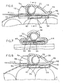
- the locking ball 32 is movable between a threading position, shown in FIG 6, wherein the ball 32 is disposed engaging finger 56 adjacent exit face 50 and a locking position, shown in FIG 9, wherein the ball 32 is closer to entry face 48 and securely engages the threaded strap 28. In its threading position, the ball 32 concurrently engages the finger 56 and roof 38.
- tip 60 of the strap 28 is inserted into the locking head 24.
- Continued threading of the strap 28 results in positive engagement of the strap 28 and ball 32 at any angle the head 24 is held.
- locking ball 32 moves to its locking position, shown in FIG 9, where the strap 28 is compressively held between the ball 32 and the floor 54 resulting in the ball 32 deforming the threaded strap 28 into the aperture 36.
- the diameter of the ball 32 is equal to or greater than the diameter of aperture 36.
- aperture 36 is substantially circular and is positioned to provide mechanical locking force.
- the disclosed invention provides a cable tie that utilises a roller means as the locking mechanism. It should be noted that the above-described and illustrated embodiments and preferred embodiments of the invention are not an exhaustive listing of the forms such a cable tie in accordance with the invention might take; rather, they serve as exemplary and illustrative of embodiments of the invention as presently understood. By way of example, and without limitation, a cable tie strap having more than one aperture is contemplated to be within the scope of the invention. Many other forms of the invention are believed to exist.
Landscapes
- Engineering & Computer Science (AREA)
- General Engineering & Computer Science (AREA)
- Mechanical Engineering (AREA)
- Architecture (AREA)
- Civil Engineering (AREA)
- Structural Engineering (AREA)
- Package Frames And Binding Bands (AREA)
- Clamps And Clips (AREA)
- Basic Packing Technique (AREA)
- Installation Of Indoor Wiring (AREA)
- Flexible Shafts (AREA)
- Communication Cables (AREA)
Abstract
Description
Claims (14)
- A cable tie, comprising:wherein the first end of the strap comprises an aperture for co-operating with said roller means for said locking engagement.an elongated metallic strap having a first end and a second end opposite the first end;a metallic locking head secured to the first end of the strap for receiving the second end of the strap, the head comprising a strap entry face, a strap exit face, and a strap-receiving aperture extending therebetween, the head further comprising a floor and a roof which diverge in the direction of the exit face; andmetallic roller means for lockingly engaging the strap, the head comprising retention means disposed adjacent the exit face for captively holding the roller means within the head;the roller means being movable between a threading position wherein the roller means is disposed adjacent the exit face and the retention means, and a locking position wherein the roller means is closer to the entry face;
- The cable tie of claim 1 wherein said aperture is dispersed beneath the locking position of the roller means.
- The cable tie of claim 1 wherein the strap and the head are made of stainless steel.
- The cable tie of claim 1 wherein the strap is coated.
- The cable tie of claim 1 wherein the roller means comprises a ball.
- The cable tie of claim 5 wherein the aperture is substantially circular.
- The cable tie of claim 6 wherein the ball has a diameter, the diameter of the ball is equal to or greater than the diameter of the aperture.
- The cable tie of claim 1 wherein the retention means comprises a finger extending from the roof adjacent the exit face.
- The cable tie of claim 1 wherein the strap has a width and the aperture has a width, the width of the strap is at least twice the width of the aperture.
- The cable tie of claim 1, which said aperture comprises a non-rectangular aperture disposed within the locking head.
- A cable tie, comprising:wherein the first end of the strap comprises a first aperture disposed beneath the locking position of the roller means.an elongated metallic strap having a first end and a second end opposite the first end;a metallic locking head secured to the first end of the strap for receiving the second end of the strap, the head comprising a strap entry face, a strap exit face, and a strap-receiving aperture extending therebetween, the head further comprising a floor and a roof which diverge in the direction of the exit face; andmetallic roller means for lockingly engaging the strap, the head comprising retention means disposed adjacent the exit face for captively holding the roller means within the head;the roller means being movable between a threading position wherein the roller means is disposed adjacent the exit face and the retention means, and a locking position wherein the roller means is closer to the entry face;
- The cable tie of claim 2 wherein the head has a bottom wall and a second aperture disposed within the bottom wall.
- The cable tie of claim 12 wherein the ball has a diameter and the second aperture has a diameter, the diameter of the ball is equal or greater than the diameter of the second aperture.
- The cable tie of claim 12 or 13 wherein the second aperture is disposed beneath the first aperture.
Applications Claiming Priority (4)
| Application Number | Priority Date | Filing Date | Title |
|---|---|---|---|
| US37744802P | 2002-05-02 | 2002-05-02 | |
| US377448P | 2002-05-02 | ||
| US201016 | 2002-07-23 | ||
| US10/201,016 US6647596B1 (en) | 2002-05-02 | 2002-07-23 | Ball lock cable tie having a strap aperture |
Publications (2)
| Publication Number | Publication Date |
|---|---|
| EP1359356A1 true EP1359356A1 (en) | 2003-11-05 |
| EP1359356B1 EP1359356B1 (en) | 2005-09-28 |
Family
ID=29218392
Family Applications (1)
| Application Number | Title | Priority Date | Filing Date |
|---|---|---|---|
| EP03252771A Expired - Lifetime EP1359356B1 (en) | 2002-05-02 | 2003-05-01 | Ball lock cable tie |
Country Status (9)
| Country | Link |
|---|---|
| US (1) | US6647596B1 (en) |
| EP (1) | EP1359356B1 (en) |
| JP (1) | JP4520108B2 (en) |
| KR (1) | KR100526878B1 (en) |
| CN (1) | CN100352743C (en) |
| AT (1) | ATE305581T1 (en) |
| AU (1) | AU2003203897B2 (en) |
| DE (1) | DE60301686T2 (en) |
| DK (1) | DK1359356T3 (en) |
Cited By (5)
| Publication number | Priority date | Publication date | Assignee | Title |
|---|---|---|---|---|
| WO2012071229A1 (en) * | 2010-11-23 | 2012-05-31 | Panduit Corp. | Metal locking tie |
| EP2675028A3 (en) * | 2012-06-14 | 2014-03-05 | Thomas & Betts International, Inc. | Anti-slip cable tie |
| CN113833909A (en) * | 2021-09-26 | 2021-12-24 | 江苏爱索新材料科技有限公司 | A cursory device for defeated salt pipeline |
| US12209693B2 (en) | 2022-11-19 | 2025-01-28 | Easy Solar Products, Inc. | Locking apparatus for wire management |
| US12449066B2 (en) | 2022-11-19 | 2025-10-21 | Easy Solar Products, Inc. | Locking apparatus with roller for wire management |
Families Citing this family (28)
| Publication number | Priority date | Publication date | Assignee | Title |
|---|---|---|---|---|
| US7409749B2 (en) * | 2003-03-06 | 2008-08-12 | Panduit Corp. | Coated stainless steel cable tie |
| GB2425778B8 (en) * | 2004-07-06 | 2019-05-01 | E Chem Tech Ltd | Protection of reinforcing steel |
| USD530600S1 (en) | 2004-10-18 | 2006-10-24 | Panduit Corp. | Cable tie |
| KR100538671B1 (en) * | 2005-03-10 | 2005-12-23 | 동아베스텍 주식회사 | A cable tie |
| US7373695B2 (en) * | 2005-05-26 | 2008-05-20 | Panduit Corp. | Displacement lock MLT |
| DE602006006867D1 (en) * | 2005-10-20 | 2009-06-25 | Panduit Corp | METAL PULLER WITH ROTATING HANDLE AND BALLASTIC ADJUSTMENT DEVICE |
| US7458398B2 (en) * | 2005-10-20 | 2008-12-02 | Panduit Corp. | Metal tie tool with rotary gripper and ball setting device |
| US7866007B2 (en) * | 2006-03-28 | 2011-01-11 | Panduit Corp. | Retained tension metal locking tie with 360 degree seal |
| US7669293B2 (en) * | 2006-06-07 | 2010-03-02 | K.S. Terminals, Inc. | Metal cable tie having a dent in geometric shape |
| CN100533888C (en) * | 2006-10-16 | 2009-08-26 | 健和兴端子股份有限公司 | Cable tie with geometrically shaped indentations |
| US7930805B2 (en) * | 2007-01-25 | 2011-04-26 | Panduit Corp. | Retained tension multiple ball lock cable tie |
| US8225461B2 (en) * | 2007-05-30 | 2012-07-24 | Panduit Corp. | Cable tie having band thread force reduction |
| JP5452998B2 (en) * | 2009-07-02 | 2014-03-26 | ヘラマンタイトン株式会社 | Tying tool |
| JP5520532B2 (en) * | 2009-07-02 | 2014-06-11 | ヘラマンタイトン株式会社 | Tying tool |
| GB2476672B (en) * | 2010-01-04 | 2015-01-14 | Hellermanntyton Ltd | Tie |
| KR200457392Y1 (en) | 2010-03-17 | 2011-12-19 | 동아베스텍 주식회사 | Stainless cable tie with tee |
| US9126732B2 (en) * | 2011-05-06 | 2015-09-08 | Panduit Corp. | Retained tension metal locking tie and pneumatic hand tool |
| KR101283311B1 (en) * | 2011-09-15 | 2013-07-09 | 동아베스텍 주식회사 | A ball type cabletie |
| KR101292587B1 (en) | 2012-04-24 | 2013-08-16 | 동아베스텍 주식회사 | A cable tie |
| US9457942B2 (en) * | 2013-05-06 | 2016-10-04 | Panduit Corp. | Extended support clip for a metal locking tie |
| CN104670688A (en) * | 2013-12-03 | 2015-06-03 | 郑元明 | Novel steel wire rope clamp |
| WO2016014646A2 (en) * | 2014-07-22 | 2016-01-28 | Thomas & Betts International, Llc | Anti-slip cable tie |
| US9834352B2 (en) * | 2014-11-24 | 2017-12-05 | Thomas & Betts International Llc | Non-slip cable tie |
| CA2925671C (en) * | 2015-04-29 | 2019-04-02 | Thomas & Betts International Llc | Accordian strap with formed waves |
| USD1027631S1 (en) * | 2021-10-12 | 2024-05-21 | Hellermann Tyton Limited | Cable tie |
| USD1030462S1 (en) * | 2021-10-12 | 2024-06-11 | Hellermanntyton Ltd | Cable tie |
| CA3236259A1 (en) * | 2021-10-27 | 2023-05-04 | Nextracker Llc | Fastening assembly for solar power systems and tools thereof |
| US12304711B2 (en) | 2023-10-04 | 2025-05-20 | Panduit Corp. | Bi-level metal locking cleat |
Citations (5)
| Publication number | Priority date | Publication date | Assignee | Title |
|---|---|---|---|---|
| US148444A (en) * | 1874-03-10 | Improvement in cotton-bale fastenings | ||
| US4366602A (en) * | 1978-11-06 | 1983-01-04 | Panduit Corp. | Metal tie |
| US4399592A (en) * | 1980-12-08 | 1983-08-23 | Panduit Corp. | Metal tie |
| US5103534A (en) * | 1991-03-18 | 1992-04-14 | Panduit Corp. | Selectively coated cable tie |
| EP0758616A1 (en) * | 1995-08-16 | 1997-02-19 | Bowthorpe Plc | Tie |
Family Cites Families (10)
| Publication number | Priority date | Publication date | Assignee | Title |
|---|---|---|---|---|
| US3015865A (en) | 1960-05-24 | 1962-01-09 | John J Rapuzzi | Universal inserted ball type buckle |
| US3351989A (en) * | 1966-12-05 | 1967-11-14 | Sterling Automotive Mfg Co Inc | Hose clamp |
| US3879811A (en) * | 1974-05-14 | 1975-04-29 | Peter Leverton | Constrictible band clips |
| US4128919A (en) | 1977-09-26 | 1978-12-12 | Panduit Corp. | Metal tie |
| US4473925A (en) | 1982-07-12 | 1984-10-02 | Houdaille Industries, Inc. | Band clamp |
| US5759004A (en) | 1993-04-20 | 1998-06-02 | Panduit Corp. | MLT bent leg pushmount |
| US5291637A (en) | 1993-06-01 | 1994-03-08 | Jonathan Meyers | Vibration resistant metallic tie |
| US5850674A (en) | 1996-09-09 | 1998-12-22 | Band-It-Idex, Inc. | Smooth band clamp with movable locking element |
| US6076235A (en) | 1999-04-20 | 2000-06-20 | Thomas & Betts International, Inc | Cable tie |
| US6014792A (en) | 1998-10-20 | 2000-01-18 | Band-It-Idex, Inc. | Band clamp including band and separately attached buckle |
-
2002
- 2002-07-23 US US10/201,016 patent/US6647596B1/en not_active Expired - Lifetime
-
2003
- 2003-04-29 AU AU2003203897A patent/AU2003203897B2/en not_active Ceased
- 2003-04-30 CN CNB031241638A patent/CN100352743C/en not_active Expired - Fee Related
- 2003-04-30 KR KR10-2003-0027427A patent/KR100526878B1/en not_active Expired - Fee Related
- 2003-05-01 EP EP03252771A patent/EP1359356B1/en not_active Expired - Lifetime
- 2003-05-01 DK DK03252771T patent/DK1359356T3/en active
- 2003-05-01 AT AT03252771T patent/ATE305581T1/en not_active IP Right Cessation
- 2003-05-01 DE DE60301686T patent/DE60301686T2/en not_active Expired - Lifetime
- 2003-05-02 JP JP2003126969A patent/JP4520108B2/en not_active Expired - Fee Related
Patent Citations (6)
| Publication number | Priority date | Publication date | Assignee | Title |
|---|---|---|---|---|
| US148444A (en) * | 1874-03-10 | Improvement in cotton-bale fastenings | ||
| US4366602A (en) * | 1978-11-06 | 1983-01-04 | Panduit Corp. | Metal tie |
| US4366602B1 (en) * | 1978-11-06 | 1994-05-17 | Panduit Corp | Metal tie |
| US4399592A (en) * | 1980-12-08 | 1983-08-23 | Panduit Corp. | Metal tie |
| US5103534A (en) * | 1991-03-18 | 1992-04-14 | Panduit Corp. | Selectively coated cable tie |
| EP0758616A1 (en) * | 1995-08-16 | 1997-02-19 | Bowthorpe Plc | Tie |
Cited By (10)
| Publication number | Priority date | Publication date | Assignee | Title |
|---|---|---|---|---|
| WO2012071229A1 (en) * | 2010-11-23 | 2012-05-31 | Panduit Corp. | Metal locking tie |
| CN103221317A (en) * | 2010-11-23 | 2013-07-24 | 泛达公司 | Metal locking tie |
| US8635745B2 (en) | 2010-11-23 | 2014-01-28 | Panduit Corp. | Metal locking tie |
| CN103221317B (en) * | 2010-11-23 | 2014-10-29 | 泛达公司 | Metal locking tie |
| EP2675028A3 (en) * | 2012-06-14 | 2014-03-05 | Thomas & Betts International, Inc. | Anti-slip cable tie |
| US9254949B2 (en) | 2012-06-14 | 2016-02-09 | Thomas & Betts International, Inc. | Anti-slip cable tie |
| CN113833909A (en) * | 2021-09-26 | 2021-12-24 | 江苏爱索新材料科技有限公司 | A cursory device for defeated salt pipeline |
| US12209693B2 (en) | 2022-11-19 | 2025-01-28 | Easy Solar Products, Inc. | Locking apparatus for wire management |
| US12449066B2 (en) | 2022-11-19 | 2025-10-21 | Easy Solar Products, Inc. | Locking apparatus with roller for wire management |
| US12467556B2 (en) | 2022-11-19 | 2025-11-11 | Easy Solar Products, Inc. | Locking apparatus for wire management with slack cable management |
Also Published As
| Publication number | Publication date |
|---|---|
| US20030204936A1 (en) | 2003-11-06 |
| DE60301686D1 (en) | 2006-02-09 |
| KR20030086917A (en) | 2003-11-12 |
| AU2003203897B2 (en) | 2008-02-14 |
| US6647596B1 (en) | 2003-11-18 |
| ATE305581T1 (en) | 2005-10-15 |
| AU2003203897A1 (en) | 2003-11-20 |
| EP1359356B1 (en) | 2005-09-28 |
| CN1454824A (en) | 2003-11-12 |
| JP4520108B2 (en) | 2010-08-04 |
| JP2004001891A (en) | 2004-01-08 |
| DK1359356T3 (en) | 2005-10-17 |
| KR100526878B1 (en) | 2005-11-08 |
| CN100352743C (en) | 2007-12-05 |
| DE60301686T2 (en) | 2006-07-06 |
Similar Documents
| Publication | Publication Date | Title |
|---|---|---|
| EP1359356B1 (en) | Ball lock cable tie | |
| EP1359357B1 (en) | Ball lock cable tie | |
| US7930805B2 (en) | Retained tension multiple ball lock cable tie | |
| US4399592A (en) | Metal tie | |
| AU2003213504B2 (en) | Ball lock cable tie having stiffening ribs | |
| US8250716B2 (en) | Retained tension metal locking tie with 360 degree seal | |
| EP2643234B1 (en) | Metal locking tie | |
| US6076235A (en) | Cable tie | |
| US20060288539A1 (en) | Displacement lock mlt | |
| KR20100017475A (en) | Cable tie having band thread force reduction | |
| JP2003102121A (en) | Cable tie with thread force-reducing structure | |
| AU539762B2 (en) | Metal tie | |
| AU7899081A (en) | Metal tie |
Legal Events
| Date | Code | Title | Description |
|---|---|---|---|
| PUAI | Public reference made under article 153(3) epc to a published international application that has entered the european phase |
Free format text: ORIGINAL CODE: 0009012 |
|
| AK | Designated contracting states |
Kind code of ref document: A1 Designated state(s): AT BE BG CH CY CZ DE DK EE ES FI FR GB GR HU IE IT LI LU MC NL PT RO SE SI SK TR |
|
| AX | Request for extension of the european patent |
Extension state: AL LT LV MK |
|
| 17P | Request for examination filed |
Effective date: 20040301 |
|
| 17Q | First examination report despatched |
Effective date: 20040512 |
|
| AKX | Designation fees paid |
Designated state(s): AT BE BG CH CY CZ DE DK EE ES FI FR GB GR HU IE IT LI LU MC NL PT RO SE SI SK TR |
|
| AXX | Extension fees paid |
Extension state: MK Payment date: 20030513 Extension state: LT Payment date: 20030513 Extension state: LV Payment date: 20030513 Extension state: AL Payment date: 20030513 |
|
| GRAP | Despatch of communication of intention to grant a patent |
Free format text: ORIGINAL CODE: EPIDOSNIGR1 |
|
| GRAS | Grant fee paid |
Free format text: ORIGINAL CODE: EPIDOSNIGR3 |
|
| GRAA | (expected) grant |
Free format text: ORIGINAL CODE: 0009210 |
|
| AK | Designated contracting states |
Kind code of ref document: B1 Designated state(s): AT BE BG CH CY CZ DE DK EE ES FI FR GB GR HU IE IT LI LU MC NL PT RO SE SI SK TR |
|
| AX | Request for extension of the european patent |
Extension state: AL LT LV MK |
|
| PG25 | Lapsed in a contracting state [announced via postgrant information from national office to epo] |
Ref country code: AT Free format text: LAPSE BECAUSE OF FAILURE TO SUBMIT A TRANSLATION OF THE DESCRIPTION OR TO PAY THE FEE WITHIN THE PRESCRIBED TIME-LIMIT Effective date: 20050928 Ref country code: LI Free format text: LAPSE BECAUSE OF FAILURE TO SUBMIT A TRANSLATION OF THE DESCRIPTION OR TO PAY THE FEE WITHIN THE PRESCRIBED TIME-LIMIT Effective date: 20050928 Ref country code: SI Free format text: LAPSE BECAUSE OF FAILURE TO SUBMIT A TRANSLATION OF THE DESCRIPTION OR TO PAY THE FEE WITHIN THE PRESCRIBED TIME-LIMIT Effective date: 20050928 Ref country code: RO Free format text: LAPSE BECAUSE OF FAILURE TO SUBMIT A TRANSLATION OF THE DESCRIPTION OR TO PAY THE FEE WITHIN THE PRESCRIBED TIME-LIMIT Effective date: 20050928 Ref country code: NL Free format text: LAPSE BECAUSE OF FAILURE TO SUBMIT A TRANSLATION OF THE DESCRIPTION OR TO PAY THE FEE WITHIN THE PRESCRIBED TIME-LIMIT Effective date: 20050928 Ref country code: CZ Free format text: LAPSE BECAUSE OF FAILURE TO SUBMIT A TRANSLATION OF THE DESCRIPTION OR TO PAY THE FEE WITHIN THE PRESCRIBED TIME-LIMIT Effective date: 20050928 Ref country code: SK Free format text: LAPSE BECAUSE OF FAILURE TO SUBMIT A TRANSLATION OF THE DESCRIPTION OR TO PAY THE FEE WITHIN THE PRESCRIBED TIME-LIMIT Effective date: 20050928 Ref country code: CH Free format text: LAPSE BECAUSE OF FAILURE TO SUBMIT A TRANSLATION OF THE DESCRIPTION OR TO PAY THE FEE WITHIN THE PRESCRIBED TIME-LIMIT Effective date: 20050928 Ref country code: BE Free format text: LAPSE BECAUSE OF FAILURE TO SUBMIT A TRANSLATION OF THE DESCRIPTION OR TO PAY THE FEE WITHIN THE PRESCRIBED TIME-LIMIT Effective date: 20050928 |
|
| REG | Reference to a national code |
Ref country code: GB Ref legal event code: FG4D |
|
| REG | Reference to a national code |
Ref country code: CH Ref legal event code: EP |
|
| REG | Reference to a national code |
Ref country code: DK Ref legal event code: T3 |
|
| REG | Reference to a national code |
Ref country code: IE Ref legal event code: FG4D |
|
| PG25 | Lapsed in a contracting state [announced via postgrant information from national office to epo] |
Ref country code: GR Free format text: LAPSE BECAUSE OF FAILURE TO SUBMIT A TRANSLATION OF THE DESCRIPTION OR TO PAY THE FEE WITHIN THE PRESCRIBED TIME-LIMIT Effective date: 20051228 Ref country code: BG Free format text: LAPSE BECAUSE OF FAILURE TO SUBMIT A TRANSLATION OF THE DESCRIPTION OR TO PAY THE FEE WITHIN THE PRESCRIBED TIME-LIMIT Effective date: 20051228 |
|
| PG25 | Lapsed in a contracting state [announced via postgrant information from national office to epo] |
Ref country code: ES Free format text: LAPSE BECAUSE OF FAILURE TO SUBMIT A TRANSLATION OF THE DESCRIPTION OR TO PAY THE FEE WITHIN THE PRESCRIBED TIME-LIMIT Effective date: 20060108 |
|
| REG | Reference to a national code |
Ref country code: SE Ref legal event code: TRGR |
|
| REF | Corresponds to: |
Ref document number: 60301686 Country of ref document: DE Date of ref document: 20060209 Kind code of ref document: P |
|
| PG25 | Lapsed in a contracting state [announced via postgrant information from national office to epo] |
Ref country code: PT Free format text: LAPSE BECAUSE OF FAILURE TO SUBMIT A TRANSLATION OF THE DESCRIPTION OR TO PAY THE FEE WITHIN THE PRESCRIBED TIME-LIMIT Effective date: 20060228 |
|
| NLV1 | Nl: lapsed or annulled due to failure to fulfill the requirements of art. 29p and 29m of the patents act | ||
| LTIE | Lt: invalidation of european patent or patent extension |
Effective date: 20050928 |
|
| PG25 | Lapsed in a contracting state [announced via postgrant information from national office to epo] |
Ref country code: HU Free format text: LAPSE BECAUSE OF FAILURE TO SUBMIT A TRANSLATION OF THE DESCRIPTION OR TO PAY THE FEE WITHIN THE PRESCRIBED TIME-LIMIT Effective date: 20060329 |
|
| REG | Reference to a national code |
Ref country code: CH Ref legal event code: PL |
|
| PG25 | Lapsed in a contracting state [announced via postgrant information from national office to epo] |
Ref country code: IE Free format text: LAPSE BECAUSE OF NON-PAYMENT OF DUE FEES Effective date: 20060501 |
|
| PG25 | Lapsed in a contracting state [announced via postgrant information from national office to epo] |
Ref country code: MC Free format text: LAPSE BECAUSE OF NON-PAYMENT OF DUE FEES Effective date: 20060531 |
|
| ET | Fr: translation filed | ||
| PLBE | No opposition filed within time limit |
Free format text: ORIGINAL CODE: 0009261 |
|
| STAA | Information on the status of an ep patent application or granted ep patent |
Free format text: STATUS: NO OPPOSITION FILED WITHIN TIME LIMIT |
|
| 26N | No opposition filed |
Effective date: 20060629 |
|
| REG | Reference to a national code |
Ref country code: IE Ref legal event code: MM4A |
|
| PG25 | Lapsed in a contracting state [announced via postgrant information from national office to epo] |
Ref country code: EE Free format text: LAPSE BECAUSE OF FAILURE TO SUBMIT A TRANSLATION OF THE DESCRIPTION OR TO PAY THE FEE WITHIN THE PRESCRIBED TIME-LIMIT Effective date: 20050928 |
|
| PG25 | Lapsed in a contracting state [announced via postgrant information from national office to epo] |
Ref country code: LU Free format text: LAPSE BECAUSE OF NON-PAYMENT OF DUE FEES Effective date: 20060501 Ref country code: TR Free format text: LAPSE BECAUSE OF FAILURE TO SUBMIT A TRANSLATION OF THE DESCRIPTION OR TO PAY THE FEE WITHIN THE PRESCRIBED TIME-LIMIT Effective date: 20050928 |
|
| PG25 | Lapsed in a contracting state [announced via postgrant information from national office to epo] |
Ref country code: CY Free format text: LAPSE BECAUSE OF FAILURE TO SUBMIT A TRANSLATION OF THE DESCRIPTION OR TO PAY THE FEE WITHIN THE PRESCRIBED TIME-LIMIT Effective date: 20050928 |
|
| REG | Reference to a national code |
Ref country code: FR Ref legal event code: PLFP Year of fee payment: 13 |
|
| REG | Reference to a national code |
Ref country code: FR Ref legal event code: PLFP Year of fee payment: 14 |
|
| REG | Reference to a national code |
Ref country code: FR Ref legal event code: PLFP Year of fee payment: 15 |
|
| REG | Reference to a national code |
Ref country code: FR Ref legal event code: PLFP Year of fee payment: 16 |
|
| PGFP | Annual fee paid to national office [announced via postgrant information from national office to epo] |
Ref country code: DE Payment date: 20200528 Year of fee payment: 18 Ref country code: FI Payment date: 20200528 Year of fee payment: 18 Ref country code: DK Payment date: 20200528 Year of fee payment: 18 Ref country code: FR Payment date: 20200525 Year of fee payment: 18 |
|
| PGFP | Annual fee paid to national office [announced via postgrant information from national office to epo] |
Ref country code: IT Payment date: 20200522 Year of fee payment: 18 Ref country code: GB Payment date: 20200527 Year of fee payment: 18 Ref country code: SE Payment date: 20200601 Year of fee payment: 18 |
|
| REG | Reference to a national code |
Ref country code: DE Ref legal event code: R119 Ref document number: 60301686 Country of ref document: DE |
|
| REG | Reference to a national code |
Ref country code: FI Ref legal event code: MAE |
|
| REG | Reference to a national code |
Ref country code: DK Ref legal event code: EBP Effective date: 20210531 |
|
| REG | Reference to a national code |
Ref country code: SE Ref legal event code: EUG |
|
| GBPC | Gb: european patent ceased through non-payment of renewal fee |
Effective date: 20210501 |
|
| PG25 | Lapsed in a contracting state [announced via postgrant information from national office to epo] |
Ref country code: FI Free format text: LAPSE BECAUSE OF NON-PAYMENT OF DUE FEES Effective date: 20210501 Ref country code: SE Free format text: LAPSE BECAUSE OF NON-PAYMENT OF DUE FEES Effective date: 20210502 |
|
| PG25 | Lapsed in a contracting state [announced via postgrant information from national office to epo] |
Ref country code: GB Free format text: LAPSE BECAUSE OF NON-PAYMENT OF DUE FEES Effective date: 20210501 Ref country code: DK Free format text: LAPSE BECAUSE OF NON-PAYMENT OF DUE FEES Effective date: 20210531 Ref country code: DE Free format text: LAPSE BECAUSE OF NON-PAYMENT OF DUE FEES Effective date: 20211201 |
|
| PG25 | Lapsed in a contracting state [announced via postgrant information from national office to epo] |
Ref country code: FR Free format text: LAPSE BECAUSE OF NON-PAYMENT OF DUE FEES Effective date: 20210531 |
|
| PG25 | Lapsed in a contracting state [announced via postgrant information from national office to epo] |
Ref country code: IT Free format text: LAPSE BECAUSE OF NON-PAYMENT OF DUE FEES Effective date: 20200501 |
|
| PG25 | Lapsed in a contracting state [announced via postgrant information from national office to epo] |
Ref country code: IT Free format text: LAPSE BECAUSE OF NON-PAYMENT OF DUE FEES Effective date: 20210501 |