EP1359319A2 - Fuel injector - Google Patents
Fuel injector Download PDFInfo
- Publication number
- EP1359319A2 EP1359319A2 EP03252437A EP03252437A EP1359319A2 EP 1359319 A2 EP1359319 A2 EP 1359319A2 EP 03252437 A EP03252437 A EP 03252437A EP 03252437 A EP03252437 A EP 03252437A EP 1359319 A2 EP1359319 A2 EP 1359319A2
- Authority
- EP
- European Patent Office
- Prior art keywords
- fuel
- valve needle
- pressure
- injector
- chamber
- Prior art date
- Legal status (The legal status is an assumption and is not a legal conclusion. Google has not performed a legal analysis and makes no representation as to the accuracy of the status listed.)
- Granted
Links
Images


Classifications
-
- F—MECHANICAL ENGINEERING; LIGHTING; HEATING; WEAPONS; BLASTING
- F02—COMBUSTION ENGINES; HOT-GAS OR COMBUSTION-PRODUCT ENGINE PLANTS
- F02M—SUPPLYING COMBUSTION ENGINES IN GENERAL WITH COMBUSTIBLE MIXTURES OR CONSTITUENTS THEREOF
- F02M61/00—Fuel-injectors not provided for in groups F02M39/00 - F02M57/00 or F02M67/00
- F02M61/16—Details not provided for in, or of interest apart from, the apparatus of groups F02M61/02 - F02M61/14
- F02M61/20—Closing valves mechanically, e.g. arrangements of springs or weights or permanent magnets; Damping of valve lift
- F02M61/205—Means specially adapted for varying the spring tension or assisting the spring force to close the injection-valve, e.g. with damping of valve lift
Definitions
- the invention relates to a fuel injector for use in delivering fuel to a combustion space of an internal combustion engine.
- the invention relates to a unit injector for an internal combustion engine or to an injector for use with a unit pump for an internal combustion engine.
- a pumping element is operable to pressurise fuel within a pumping chamber to a high level, and delivers fuel to an associated injector delivery chamber.
- the injector is arranged within a common housing with the pump components and a high pressure fuel line defined within the common housing provides a communication path between the pumping chamber and the injector delivery chamber.
- the injector includes a valve needle which is slidable within a bore provided in a nozzle body housing and engageable with a valve needle seating to control fuel delivery, through one or more injector outlets, to an associated engine cylinder.
- the valve needle is typically spring biased towards the seating by means of a spring located within a chamber at an end of the valve needle remote from the outlet.
- the pump elements are usually remotely spaced from the injector components and a separate high pressure fuel line connects a pump outlet to an injector inlet. Such arrangements may also be referred to as "unit pump/injector" arrangements.
- the pumping element takes the form of a pumping plunger which is reciprocable within a plunger bore under the influence of a drive arrangement to pressurise fuel within the pumping chamber.
- a spill valve is operable to open and close communication between the pumping chamber and a low pressure drain. When the spill valve is open, reciprocal movement of the pumping plunger within the bore will cause fuel to be drawn into and displaced from the pumping chamber to the low pressure drain. When the spill valve is closed, communication between the pumping chamber and the low pressure drain is broken so that reciprocal movement of the plunger causes fuel pressure within the pumping chamber to increase.
- a point will be reached during pumping at which the hydraulic forces acting on thrust surfaces of the valve needle due to the supply of high fuel pressure to the delivery chamber are sufficient to overcome the force of the spring, and the valve needle is caused to lift from its seating to commence injection.
- the pressure at which the injector is caused to lift from its seating is commonly referred to as the "nozzle opening pressure”. If the spill valve is opened, fuel within the pumping chamber is displaced to drain as plunger movement continues and the valve needle is returned to its seated position, by means of the spring force, to terminate injection.
- the spring pre-load determines the pressure at which valve needle opening occurs, and this is typically set by means of a shim located between an end of the valve needle remote from injector outlet and the spring.
- the injector For some applications it is desirable for the injector to have a variable nozzle opening pressure. In particular, it is desirable for the nozzle opening pressure to be relatively high for mid-engine speeds, and lower at rated (maximum) engine speed. It is known to achieve a variable nozzle opening pressure by providing the injector with an electronically controlled injection control valve for actuating valve needle movement, but such systems are relatively complex and costly.
- a fuel injector for an internal combustion engine comprising:
- the injector may form part of a fuel system including a pump having a pumping plunger which is operable to pressurise fuel within a pumping chamber from where fuel is supplied to the delivery chamber of the injector.
- the pump has an associated spill valve to control communication between the pump chamber and a low pressure drain. When the spill valve is open, movement of the pumping plunger causes fuel to be drawn into and displaced from the pumping chamber, and when the spill valve is closed fuel is unable to escape to the low pressure drain such that fuel within the pumping chamber is pressurised and a pressure wave is delivered to the high pressure supply passage.
- the injector includes a piston associated with the valve needle, wherein a surface of the piston defines the pressure chamber.
- the injector includes a spring for urging the valve needle towards the valve needle seating.
- the spring is housed within a spring chamber and is preferably engaged between a first surface associated with the valve needle and a shim located within the spring chamber. Appropriate selection of the shim enables the spring pre-load to be set to a desired amount.
- the spring may be engaged between a first surface associated with the valve needle and a surface of the spring chamber.
- the piston acts on the valve needle through a push rod which extends through the spring
- a surface of the valve needle defines the pressure chamber.
- the injector includes a first restricted flow path for fuel between the high pressure supply passage and the pressure chamber to permit a continuous flow of high pressure fuel into the pressure chamber at a restricted rate, and a second restricted flow path between the pressure chamber and a low pressure drain to permit a continuous flow of fuel to the low pressure drain at a restricted rate.
- the first restricted flow path is arranged adjacent to the second restricted flow path in a common housing part.
- the injector includes a first flow path between an injector inlet and the delivery chamber, and a second flow path between the injector inlet and the pressure chamber, wherein the first and second flow paths have different flow lengths.
- the high pressure supply passage is preferably defined by a first drilling provided in a further injector housing.
- both the first flow path and the second flow path are defined, in part, by a common region of the high pressure supply passage, and the second flow path is further defined by a second drilling defined, at least in part, within said further injector housing.
- the second drilling preferably communicates with the first drilling through a branch passage defined by a recess provided in an upper surface of an injector housing.
- the high pressure supply passage is provided with a restriction to reduce the pressure of fuel acting on a thrust surface of the valve needle during injection to a level below that prior to injection.
- a fuel pump comprising:
- the fuel pump typically takes the form of a so-called "unit injector" in which the pumping plunger and the injector are arranged within a common unit.
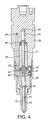
- an injector in accordance with a first embodiment of the invention includes a nozzle body 10 provided with a blind bore 12 within which a valve needle 14 is slidable.
- the valve needle 14 is engageable with a valve needle seating (not identified) to control fuel delivery through one or more injector outlets (not shown) into an associated engine cylinder or other combustion space.
- the valve needle 14 is provided with a plurality of flats, slots or grooves 16 on its outer surface which permit fuel to flow from an annular chamber 18 defined by an enlarged region of the bore 12 to a delivery chamber 20 defined by a downstream region of the bore 12.
- the valve needle 14 also includes one or more thrust surfaces (not shown) exposed to fuel pressure within the delivery chamber 20 such that a force due to fuel pressure acting on the thrust surface serves to urge the valve needle 14 away from the valve needle seating.
- the annular chamber 18 receives fuel at high pressure through a high pressure supply passage 22 defined by a plurality of drillings provided in various injector housing parts.
- the high pressure supply passage 22 communicates with an injector inlet 24 which receives pressurised fuel from a fuel pump (not shown).
- the pump is of the type including a pumping plunger which is driven to pressurise fuel within a pumping chamber.
- a spill valve of the pump is operable to control communication between the pumping chamber and a low pressure drain so that when the spill valve is open, movement of the pumping plunger causes fuel to be drawn into and displaced from the pumping chamber, and when the spill valve is closed fuel is unable to escape to the low pressure drain such that fuel within the pump chamber is pressurised to a high level as the pumping plunger performs a pumping stroke.
- High pressure fuel is typically delivered from the pumping chamber to the inlet 24 of the injector under the control of a delivery valve.
- a first injector housing part 23 provided with a stepped blind bore, a lower portion of which defines a spring chamber 26 housing a compression spring 28.
- One end of the spring 28 acts on an upper surface of the valve needle 14 and the other end of the spring 28 engages the step in the bore within the chamber 26, such that the spring 28 urges the valve needle 14 towards the valve needle seating.
- the piston 30 is slidable within the bore in the injector housing 23 and is coupled to the valve needle 14 through a push rod (not visible in the view shown) which extends through the spring 28.
- an upper surface of the piston 30 defines, together with the blind end of the bore in the injector housing 23, a pressure chamber 32 which communicates continuously with a portion of the high pressure supply passage 22 through a first restriction 34 defined by a drilling in the injector housing 23.
- a low pressure drain passage 36 provides a return flow path for leakage fuel in the spring chamber 26 to low pressure, the low pressure drain passage 36 being defined partially within the first injector housing 23 and partially within a second injector housing 38 in abutment with the first injector housing 23.
- the pressure chamber 32 communicates with the low pressure drain passage 36 through a second restriction 40 defined by an additional drilling in the first injector housing part 23, in a position generally adjacent to the first restriction 34.
- the second restriction 40 permits a continuous flow of fuel from the pressure chamber 32 to low pressure at a restricted rate.
- the first restriction 34 permits fuel to flow from the high pressure flow passage 22 into the pressure chamber 32 at a restricted rate, fuel delivered to the pressure chamber 32 also being able to flow continuously from the pressure chamber 32 to the low pressure passage 36 at restricted rate through the second restriction 40, as shown in Figure 2.
- the first and second restrictions 34, 40 respectively may be shaped to enable similar or the same rates of fuel flow therethrough, or different flow rates.
- the first and second housing parts 23, 38 and the upper end of the nozzle body 10 are received within a cap nut 42 in a conventional manner.
- the injector takes the form of a so-called "unit injector"
- the pumping plunger and associated pump components of the pump for supplying high pressure fuel to the delivery chamber 20 are arranged within a common housing.
- a point will be reached at which the force acting on the valve needle thrust surface due to fuel pressure within the delivery chamber 20 is sufficient to overcome the combined force of the spring 28 and the force due to fuel pressure within the pressure chamber 32 acting on the piston 30, and the valve needle 14 is caused to lift away from the valve needle seating to commence injection.
- the nozzle opening pressure at which the valve needle 14 is caused to lift from the valve needle seating to initiate injection is determined by the force due to fuel pressure within the delivery chamber 20 acting on the surface area of the thrust surface of the valve needle, the pre-load of the spring 28 and the force due to fuel pressure within the pressure chamber 32 acting on the surface area of the piston 30.
- the pressure difference between the pressure chamber 32 and the delivery chamber 20 therefore influences the nozzle opening pressure and, as the characteristics of the pressure wave through the high pressure supply passage 22 are dependent upon pumping speed (as determined by engine speed), this pressure difference, and hence the nozzle opening pressure, will vary with engine speed.
- the spill valve of the pump When it is desired to terminate injection, the spill valve of the pump is open such that further plunger movement simply draws fuel into and displaces fuel out of the pumping chamber, and the pressure of fuel delivered to the high pressure supply passage 22 is reduced.
- fuel pressure within the delivery chamber 20 is reduced below the predetermined amount at which the upward force acting on the valve needle thrust surface is overcome by the force of the spring 28 acting in combination with fuel pressure within the pressure chamber 32, the valve needle 14 is urged against the valve needle seating to terminate injection.
- the piston 30 may be coupled to the valve needle 14 directly, in which case the push rod is integrally formed with the piston 30. In this embodiment, it is effectively a surface of the valve needle which is exposed to fuel pressure within the pressure chamber 32.
- FIGS 3 to 5 illustrate three sectional views of a further alternative embodiment of the invention.
- a lower surface of the piston 30 abuts one end of a push rod 41, the other end of which is coupled to the valve needle 14 through a load transmitting member 43.
- the load transmitting member 43 defines a seat for one end of the spring 28, the other end of the spring 28 being engaged with a shim 44 located at an upper end of the spring chamber 26.
- the shim 44 is selected to provide the desired spring pre-load which, in turn, influences the nozzle opening pressure, as described in further detail below.
- the injector in Figures 3 to 5 differs from that in Figure 1 in that the force acting on the valve needle 14 to urge the needle away from the seating acts on a thrust surface exposed to fuel pressure within the annular chamber 18, and the flats 16 and the delivery chamber 20 in the nozzle of Figure 1 are omitted. Movement of the valve needle 14 in the embodiment shown in Figures 3 to 5 is effected in the same way, however, and occurs when fuel pressure within the annular chamber 18 is sufficient to overcome the combined force of a spring and fuel pressure acting on the back end of the needle, as described in further detail below.
- the injector in Figures 3 to 5 also differs from that in Figures 1 and 2 in that the upper end of the nozzle body 10 abuts a first face of an adapter plate 46 through which a portion of the high pressure supply passage 22 extends, the opposing face of the adapter plate 46 being in abutment with the second injector housing 38.
- the second injector housing 38, the adapter plate 46 and the upper end region of the nozzle body 10 are received within the cap nut 42 in a conventional manner.
- the second injector housing 38 and the adapter plate 46 are provided with correspondingly shaped drillings or recesses within which a location pin 47 is received to ensure correct alignment of parts.
- the second injector housing 38 is also provided with an additional drilling 48, one end of which communicates with the pressure chamber 32 via a cross drilling 54 in the second injector housing 38.
- the additional drilling 48 communicates with a region of the high pressure supply passage 22 through a branch passage 56 defined by a recess provided in the upper end face of the adapter plate 46.
- a first flow path is defined between the injector inlet 24 and the delivery chamber 20 by the high pressure supply passage 22, and a second flow path is defined between the injector inlet 24 and the pressure chamber 32 by a portion of the high pressure supply passage 22, the branch passage 56, the additional drilling 48 and the cross drilling 54.
- the first and second flow paths have different flow lengths.
- the nozzle opening pressure will be determined by the difference in fuel pressure between the pressure chamber 32 and the delivery chamber 20, and also by the pre-load of the spring 28. Due to the length of the additional drilling 48 through which fuel flows to the pressure chamber 32, and hence the different flow path lengths between the injector inlet 24 and the delivery chamber 20 and between the injector inlet 24 and the pressure chamber 32, the pressure wave transmitted through the high pressure supply passage 22 will reach the delivery chamber 20 in advance of the pressure wave at the pressure chamber 32. For low engine speeds, when the rate of pressure increase is low, this difference in flow path length will have a relatively less significant effect on the pressure difference across the chambers 32, 20 than for higher engine speeds when the rate of pressure increase is higher. For lower engine speeds the nozzle opening pressure is therefore higher than for higher engine speeds.
- the embodiment of Figures 3 to 5 therefore also provides the advantage that the nozzle opening pressure is variable with engine speed, from a relatively higher nozzle opening pressure at relatively low engine speeds to a relatively lower nozzle opening pressure at higher engine speeds.
- the length of the additional drilling 48 to the pressure chamber 32 may be selected to give the required variable nozzle opening pressure characteristics with engine speed.
- the branch passage 56 to the pressure chamber 32 may communicate with the high pressure supply passage 22 further downstream of the point shown in Figures 3 to 5 to create a greater difference in flow path length,
- the branch passage 56 may be defined by a recess or groove provided in an upper surface of the nozzle body 10.
- the high pressure supply passage 22 defines a common region of both the first flow path length between the injector inlet 24 and the delivery chamber 20, and the second flow path length between the injector inlet 24 and the pressure chamber 32.
- the injector may be configured such that two separate high pressure flow passages of differing flow length branch from the injector inlet 24 to the pressure chamber 32 and the delivery chamber 20 respectively.
- the supply passage 22 may be provided with a restriction (not shown in the accompanying figures) which results in a reduction in the force acting on the valve needle thrust surface when the valve needle is lifted from its seating. A smaller force is therefore required to seat the valve needle, permitting faster needle closure.
- a restriction not shown in the accompanying figures
Landscapes
- Engineering & Computer Science (AREA)
- Chemical & Material Sciences (AREA)
- Combustion & Propulsion (AREA)
- Mechanical Engineering (AREA)
- General Engineering & Computer Science (AREA)
- Fuel-Injection Apparatus (AREA)
Abstract
Description
pressure drain. When the spill valve is closed, communication between the pumping chamber and the low pressure drain is broken so that reciprocal movement of the plunger causes fuel pressure within the pumping chamber to increase.
Claims (14)
- A fuel injector for an internal combustion engine, the injector comprising:a valve needle (14) having a first surface which is engageable with a valve needle seating to control fuel flow between a delivery chamber (20) and an outlet,a high pressure supply passage (22) for supplying fuel at high pressure to the delivery chamber (20), wherein a thrust surface of the valve needle is exposed to fuel pressure within the delivery chamber (20) such that a force is applied to the valve needle (14) to urge the needle away from the valve seating,a pressure chamber (32) in communication with the high pressure supply passage (22) which is defined, in part, by a surface associated with the valve needle (14) at an end thereof remote from the outlet, andmeans (34, 40; 22, 56, 48, 54) for generating a variable difference in fuel pressure between the delivery chamber (20) and the pressure chamber (32) in dependence upon the rate of increase of fuel pressure within the high pressure supply passage (22), thereby to provide a variable nozzle opening pressure at which the valve needle (14) is caused to lift from the valve needle seating to initiate injection.
- A fuel injector as claimed in Claim 1, wherein the injector includes a piston (30) associated with the valve needle (14), wherein a surface of the piston (30) defines the pressure chamber (32).
- A fuel injector as claimed in Claim 1 or Claim 2, further comprising a spring (28) arranged within a spring chamber (26) for urging the valve needle (14) towards the valve needle seating.
- A fuel injector as claimed in Claim 3, wherein the spring (28) is engaged between a first surface associated with the valve needle (14) and a shim (44) located within the spring chamber (26).
- A fuel injector as claimed in Claim 3 or Claim 4, wherein the piston (30) acts on the valve needle (14) through a push rod (41) extending through the spring (28).
- A fuel injector as claimed in Claim 1 or Claim 2, wherein a surface of the valve needle (14) defines the pressure chamber (32).
- A fuel injector as claimed in Claim 6, further comprising a spring (28) arranged within a spring chamber (26) for urging the valve needle (14) towards the valve needle seating.
- A fuel injector as claimed in any one of Claims 1 to 7, wherein the means for generating a variable fuel pressure difference includes a first restricted flow path (34) for fuel between the high pressure supply passage (22) and the pressure chamber (32) to permit a continuous flow of high pressure fuel into the pressure chamber (32) at a restricted rate, and a second restricted flow path (40) between the pressure chamber (32) and a low pressure drain to permit a continuous flow of fuel out of the pressure chamber (32) to the low pressure drain at a restricted rate.
- A fuel injector as claimed in Claim 8, wherein the first and second restricted flow paths are defined by first and second drillings (34, 40) respectively formed in an injector housing (23), each drilling having one end in communication with the pressure chamber (32).
- A fuel injector as claimed in any one of Claims 1 to 7, wherein the injector includes a first flow path (22) between an injector inlet (24) and the delivery chamber (20), and a second flow path (22, 56, 48, 54) between the injector inlet (24) and the pressure chamber (32), wherein the first and second flow paths have different flow lengths.
- A fuel injector as claimed in Claim 10, wherein the high pressure supply passage (22) is defined by a first drilling provided in a further injector housing (38), both the first flow path and the second flow path being defined, in part, by a common region of the high pressure supply passage (22) and wherein the second flow path is further defined by a second drilling (48) defined, at least in part, within the said further injector housing (38).
- A fuel injector as claimed in Claim 11, wherein the second drilling communicates with the first drilling through a branch passage (56) defined by a recess provided in an upper surface of an additional injector housing part (46).
- A fuel injector as claimed in any one of Claims 1 to 12, wherein the valve needle (14) includes a thrust surface to which fuel pressure is applied, in use, to urge the valve needle (14) away from the valve needle seating and wherein the high pressure supply passage (22) is provided with a restriction to reduce the force acting on the thrust surface during injection to a level below that prior to injection.
- A unit fuel pump comprising:a pumping plunger which is operable to pressurise fuel within a pumping chamber,a spill valve for controlling communication between the pumping chamber and a low pressure drain, andan injector as claimed in any one of Claims 1 to 13.
Applications Claiming Priority (2)
| Application Number | Priority Date | Filing Date | Title |
|---|---|---|---|
| GBGB0209049.6A GB0209049D0 (en) | 2002-04-20 | 2002-04-20 | Fuel injector |
| GB0209049 | 2002-04-20 |
Publications (3)
| Publication Number | Publication Date |
|---|---|
| EP1359319A2 true EP1359319A2 (en) | 2003-11-05 |
| EP1359319A3 EP1359319A3 (en) | 2004-11-10 |
| EP1359319B1 EP1359319B1 (en) | 2007-05-23 |
Family
ID=9935192
Family Applications (1)
| Application Number | Title | Priority Date | Filing Date |
|---|---|---|---|
| EP03252437A Expired - Lifetime EP1359319B1 (en) | 2002-04-20 | 2003-04-16 | Fuel injector |
Country Status (4)
| Country | Link |
|---|---|
| EP (1) | EP1359319B1 (en) |
| AT (1) | ATE363024T1 (en) |
| DE (1) | DE60313914T2 (en) |
| GB (1) | GB0209049D0 (en) |
Cited By (1)
| Publication number | Priority date | Publication date | Assignee | Title |
|---|---|---|---|---|
| WO2004111439A1 (en) * | 2003-05-26 | 2004-12-23 | Robert Bosch Gmbh | Fuel injection device for an internal combustion engine |
Family Cites Families (6)
| Publication number | Priority date | Publication date | Assignee | Title |
|---|---|---|---|---|
| US4684067A (en) * | 1986-03-21 | 1987-08-04 | General Motors Corporation | Two-stage, hydraulic-assisted fuel injection nozzle |
| GB9520243D0 (en) * | 1995-10-04 | 1995-12-06 | Lucas Ind Plc | Injector |
| DE19752496A1 (en) * | 1997-11-27 | 1999-06-02 | Bosch Gmbh Robert | Fuel injection valve for internal combustion engines |
| US6604507B1 (en) * | 1998-09-10 | 2003-08-12 | International Engine Intellectual Property Company, Llc | Fuel injector |
| DE19930832A1 (en) * | 1999-07-03 | 2001-01-11 | Bosch Gmbh Robert | Fuel injector |
| DE10112426A1 (en) * | 2001-03-15 | 2002-09-19 | Bosch Gmbh Robert | Fuel injection valve has pressure chamber and spring chamber connected by throttling connection so that pressure in spring chamber after termination of injection cycle up to beginning of next cycle falls off to standing pressure |
-
2002
- 2002-04-20 GB GBGB0209049.6A patent/GB0209049D0/en not_active Ceased
-
2003
- 2003-04-16 EP EP03252437A patent/EP1359319B1/en not_active Expired - Lifetime
- 2003-04-16 AT AT03252437T patent/ATE363024T1/en not_active IP Right Cessation
- 2003-04-16 DE DE60313914T patent/DE60313914T2/en not_active Expired - Lifetime
Cited By (1)
| Publication number | Priority date | Publication date | Assignee | Title |
|---|---|---|---|---|
| WO2004111439A1 (en) * | 2003-05-26 | 2004-12-23 | Robert Bosch Gmbh | Fuel injection device for an internal combustion engine |
Also Published As
| Publication number | Publication date |
|---|---|
| GB0209049D0 (en) | 2002-05-29 |
| EP1359319A3 (en) | 2004-11-10 |
| DE60313914D1 (en) | 2007-07-05 |
| DE60313914T2 (en) | 2007-09-20 |
| ATE363024T1 (en) | 2007-06-15 |
| EP1359319B1 (en) | 2007-05-23 |
Similar Documents
| Publication | Publication Date | Title |
|---|---|---|
| US6220528B1 (en) | Fuel injector including an outer valve needle, and inner valve needle slidable within a bore formed in the outer valve needle | |
| EP1275840A2 (en) | Fuel injector with directly controlled dual concentric check needle and engine using same | |
| EP0943797A1 (en) | Fuel injector | |
| EP1163440B1 (en) | Fuel injector | |
| EP0890736B1 (en) | Injector | |
| US20030183198A1 (en) | Fuel injection device | |
| GB2279706A (en) | Fuel injection pumping system | |
| US6725840B1 (en) | Fuel injection device | |
| EP1081373A2 (en) | Fuel injector | |
| EP1098087B1 (en) | Fuel Injector | |
| US6425368B1 (en) | Fuel injector | |
| US6003497A (en) | Mechanically actuated hydraulically amplified fuel injector with electrically controlled pressure relief | |
| EP0736687B1 (en) | Fuel pumping apparatus | |
| US6837451B2 (en) | Seat/slide valve with pressure-equalizing pin | |
| EP0844383A2 (en) | Injector | |
| EP2615294A1 (en) | Fuel injector | |
| US6637409B2 (en) | Fuel injection device for internal combustion engines | |
| US6871636B2 (en) | Fuel-injection device for internal combustion engines | |
| EP1359319B1 (en) | Fuel injector | |
| US20020113140A1 (en) | Fuel injection apparatus for an internal combustion engine | |
| US6953157B2 (en) | Fuel injection device for an internal combustion engine | |
| US5992767A (en) | Injector | |
| EP1065368A2 (en) | Fuel injector | |
| US6913212B2 (en) | Oil activated fuel injector control with delay plunger | |
| US6443129B1 (en) | Pressure booster for a fuel injection system for internal combustion engines, with hydraulically reinforced refilling |
Legal Events
| Date | Code | Title | Description |
|---|---|---|---|
| PUAI | Public reference made under article 153(3) epc to a published international application that has entered the european phase |
Free format text: ORIGINAL CODE: 0009012 |
|
| AK | Designated contracting states |
Kind code of ref document: A2 Designated state(s): AT BE BG CH CY CZ DE DK EE ES FI FR GB GR HU IE IT LI LU MC NL PT RO SE SI SK TR |
|
| AX | Request for extension of the european patent |
Extension state: AL LT LV MK |
|
| PUAL | Search report despatched |
Free format text: ORIGINAL CODE: 0009013 |
|
| AK | Designated contracting states |
Kind code of ref document: A3 Designated state(s): AT BE BG CH CY CZ DE DK EE ES FI FR GB GR HU IE IT LI LU MC NL PT RO SE SI SK TR |
|
| AX | Request for extension of the european patent |
Extension state: AL LT LV MK |
|
| 17P | Request for examination filed |
Effective date: 20050503 |
|
| 17Q | First examination report despatched |
Effective date: 20050606 |
|
| AKX | Designation fees paid |
Designated state(s): AT BE BG CH CY CZ DE DK EE ES FI FR GB GR HU IE IT LI LU MC NL PT RO SE SI SK TR |
|
| 17Q | First examination report despatched |
Effective date: 20050606 |
|
| 17Q | First examination report despatched |
Effective date: 20050606 |
|
| GRAP | Despatch of communication of intention to grant a patent |
Free format text: ORIGINAL CODE: EPIDOSNIGR1 |
|
| GRAS | Grant fee paid |
Free format text: ORIGINAL CODE: EPIDOSNIGR3 |
|
| GRAA | (expected) grant |
Free format text: ORIGINAL CODE: 0009210 |
|
| AK | Designated contracting states |
Kind code of ref document: B1 Designated state(s): AT BE BG CH CY CZ DE DK EE ES FI FR GB GR HU IE IT LI LU MC NL PT RO SE SI SK TR |
|
| PG25 | Lapsed in a contracting state [announced via postgrant information from national office to epo] |
Ref country code: CH Free format text: LAPSE BECAUSE OF FAILURE TO SUBMIT A TRANSLATION OF THE DESCRIPTION OR TO PAY THE FEE WITHIN THE PRESCRIBED TIME-LIMIT Effective date: 20070523 Ref country code: FI Free format text: LAPSE BECAUSE OF FAILURE TO SUBMIT A TRANSLATION OF THE DESCRIPTION OR TO PAY THE FEE WITHIN THE PRESCRIBED TIME-LIMIT Effective date: 20070523 Ref country code: LI Free format text: LAPSE BECAUSE OF FAILURE TO SUBMIT A TRANSLATION OF THE DESCRIPTION OR TO PAY THE FEE WITHIN THE PRESCRIBED TIME-LIMIT Effective date: 20070523 |
|
| REG | Reference to a national code |
Ref country code: GB Ref legal event code: FG4D |
|
| REG | Reference to a national code |
Ref country code: CH Ref legal event code: EP |
|
| REG | Reference to a national code |
Ref country code: IE Ref legal event code: FG4D |
|
| REF | Corresponds to: |
Ref document number: 60313914 Country of ref document: DE Date of ref document: 20070705 Kind code of ref document: P |
|
| PG25 | Lapsed in a contracting state [announced via postgrant information from national office to epo] |
Ref country code: SE Free format text: LAPSE BECAUSE OF FAILURE TO SUBMIT A TRANSLATION OF THE DESCRIPTION OR TO PAY THE FEE WITHIN THE PRESCRIBED TIME-LIMIT Effective date: 20070823 |
|
| PG25 | Lapsed in a contracting state [announced via postgrant information from national office to epo] |
Ref country code: ES Free format text: LAPSE BECAUSE OF FAILURE TO SUBMIT A TRANSLATION OF THE DESCRIPTION OR TO PAY THE FEE WITHIN THE PRESCRIBED TIME-LIMIT Effective date: 20070903 |
|
| NLV1 | Nl: lapsed or annulled due to failure to fulfill the requirements of art. 29p and 29m of the patents act | ||
| ET | Fr: translation filed | ||
| PG25 | Lapsed in a contracting state [announced via postgrant information from national office to epo] |
Ref country code: AT Free format text: LAPSE BECAUSE OF FAILURE TO SUBMIT A TRANSLATION OF THE DESCRIPTION OR TO PAY THE FEE WITHIN THE PRESCRIBED TIME-LIMIT Effective date: 20070523 |
|
| REG | Reference to a national code |
Ref country code: CH Ref legal event code: PL |
|
| PG25 | Lapsed in a contracting state [announced via postgrant information from national office to epo] |
Ref country code: BE Free format text: LAPSE BECAUSE OF FAILURE TO SUBMIT A TRANSLATION OF THE DESCRIPTION OR TO PAY THE FEE WITHIN THE PRESCRIBED TIME-LIMIT Effective date: 20070523 |
|
| PG25 | Lapsed in a contracting state [announced via postgrant information from national office to epo] |
Ref country code: SI Free format text: LAPSE BECAUSE OF FAILURE TO SUBMIT A TRANSLATION OF THE DESCRIPTION OR TO PAY THE FEE WITHIN THE PRESCRIBED TIME-LIMIT Effective date: 20070523 Ref country code: BG Free format text: LAPSE BECAUSE OF FAILURE TO SUBMIT A TRANSLATION OF THE DESCRIPTION OR TO PAY THE FEE WITHIN THE PRESCRIBED TIME-LIMIT Effective date: 20070823 Ref country code: DK Free format text: LAPSE BECAUSE OF FAILURE TO SUBMIT A TRANSLATION OF THE DESCRIPTION OR TO PAY THE FEE WITHIN THE PRESCRIBED TIME-LIMIT Effective date: 20070523 Ref country code: PT Free format text: LAPSE BECAUSE OF FAILURE TO SUBMIT A TRANSLATION OF THE DESCRIPTION OR TO PAY THE FEE WITHIN THE PRESCRIBED TIME-LIMIT Effective date: 20071023 Ref country code: NL Free format text: LAPSE BECAUSE OF FAILURE TO SUBMIT A TRANSLATION OF THE DESCRIPTION OR TO PAY THE FEE WITHIN THE PRESCRIBED TIME-LIMIT Effective date: 20070523 Ref country code: CZ Free format text: LAPSE BECAUSE OF FAILURE TO SUBMIT A TRANSLATION OF THE DESCRIPTION OR TO PAY THE FEE WITHIN THE PRESCRIBED TIME-LIMIT Effective date: 20070523 |
|
| PG25 | Lapsed in a contracting state [announced via postgrant information from national office to epo] |
Ref country code: SK Free format text: LAPSE BECAUSE OF FAILURE TO SUBMIT A TRANSLATION OF THE DESCRIPTION OR TO PAY THE FEE WITHIN THE PRESCRIBED TIME-LIMIT Effective date: 20070523 |
|
| PLBE | No opposition filed within time limit |
Free format text: ORIGINAL CODE: 0009261 |
|
| STAA | Information on the status of an ep patent application or granted ep patent |
Free format text: STATUS: NO OPPOSITION FILED WITHIN TIME LIMIT |
|
| 26N | No opposition filed |
Effective date: 20080226 |
|
| PG25 | Lapsed in a contracting state [announced via postgrant information from national office to epo] |
Ref country code: GR Free format text: LAPSE BECAUSE OF FAILURE TO SUBMIT A TRANSLATION OF THE DESCRIPTION OR TO PAY THE FEE WITHIN THE PRESCRIBED TIME-LIMIT Effective date: 20070824 |
|
| PG25 | Lapsed in a contracting state [announced via postgrant information from national office to epo] |
Ref country code: RO Free format text: LAPSE BECAUSE OF FAILURE TO SUBMIT A TRANSLATION OF THE DESCRIPTION OR TO PAY THE FEE WITHIN THE PRESCRIBED TIME-LIMIT Effective date: 20070523 |
|
| PG25 | Lapsed in a contracting state [announced via postgrant information from national office to epo] |
Ref country code: MC Free format text: LAPSE BECAUSE OF NON-PAYMENT OF DUE FEES Effective date: 20080430 |
|
| GBPC | Gb: european patent ceased through non-payment of renewal fee |
Effective date: 20080416 |
|
| PG25 | Lapsed in a contracting state [announced via postgrant information from national office to epo] |
Ref country code: EE Free format text: LAPSE BECAUSE OF FAILURE TO SUBMIT A TRANSLATION OF THE DESCRIPTION OR TO PAY THE FEE WITHIN THE PRESCRIBED TIME-LIMIT Effective date: 20070523 |
|
| PG25 | Lapsed in a contracting state [announced via postgrant information from national office to epo] |
Ref country code: IE Free format text: LAPSE BECAUSE OF NON-PAYMENT OF DUE FEES Effective date: 20080416 |
|
| PG25 | Lapsed in a contracting state [announced via postgrant information from national office to epo] |
Ref country code: GB Free format text: LAPSE BECAUSE OF NON-PAYMENT OF DUE FEES Effective date: 20080416 |
|
| PG25 | Lapsed in a contracting state [announced via postgrant information from national office to epo] |
Ref country code: CY Free format text: LAPSE BECAUSE OF FAILURE TO SUBMIT A TRANSLATION OF THE DESCRIPTION OR TO PAY THE FEE WITHIN THE PRESCRIBED TIME-LIMIT Effective date: 20070523 |
|
| PG25 | Lapsed in a contracting state [announced via postgrant information from national office to epo] |
Ref country code: LU Free format text: LAPSE BECAUSE OF NON-PAYMENT OF DUE FEES Effective date: 20080416 Ref country code: HU Free format text: LAPSE BECAUSE OF FAILURE TO SUBMIT A TRANSLATION OF THE DESCRIPTION OR TO PAY THE FEE WITHIN THE PRESCRIBED TIME-LIMIT Effective date: 20071124 |
|
| PG25 | Lapsed in a contracting state [announced via postgrant information from national office to epo] |
Ref country code: TR Free format text: LAPSE BECAUSE OF FAILURE TO SUBMIT A TRANSLATION OF THE DESCRIPTION OR TO PAY THE FEE WITHIN THE PRESCRIBED TIME-LIMIT Effective date: 20070523 |
|
| REG | Reference to a national code |
Ref country code: FR Ref legal event code: TP |
|
| PGFP | Annual fee paid to national office [announced via postgrant information from national office to epo] |
Ref country code: FR Payment date: 20110426 Year of fee payment: 9 Ref country code: DE Payment date: 20110413 Year of fee payment: 9 |
|
| PGFP | Annual fee paid to national office [announced via postgrant information from national office to epo] |
Ref country code: IT Payment date: 20110420 Year of fee payment: 9 |
|
| REG | Reference to a national code |
Ref country code: FR Ref legal event code: ST Effective date: 20121228 |
|
| REG | Reference to a national code |
Ref country code: DE Ref legal event code: R119 Ref document number: 60313914 Country of ref document: DE Effective date: 20121101 |
|
| PG25 | Lapsed in a contracting state [announced via postgrant information from national office to epo] |
Ref country code: FR Free format text: LAPSE BECAUSE OF NON-PAYMENT OF DUE FEES Effective date: 20120430 Ref country code: IT Free format text: LAPSE BECAUSE OF NON-PAYMENT OF DUE FEES Effective date: 20120416 |
|
| PG25 | Lapsed in a contracting state [announced via postgrant information from national office to epo] |
Ref country code: DE Free format text: LAPSE BECAUSE OF NON-PAYMENT OF DUE FEES Effective date: 20121101 |