EP1358006B1 - Dividing device - Google Patents
Dividing device Download PDFInfo
- Publication number
- EP1358006B1 EP1358006B1 EP02700888A EP02700888A EP1358006B1 EP 1358006 B1 EP1358006 B1 EP 1358006B1 EP 02700888 A EP02700888 A EP 02700888A EP 02700888 A EP02700888 A EP 02700888A EP 1358006 B1 EP1358006 B1 EP 1358006B1
- Authority
- EP
- European Patent Office
- Prior art keywords
- vane
- hub
- dividing device
- apertures
- vanes
- Prior art date
- Legal status (The legal status is an assumption and is not a legal conclusion. Google has not performed a legal analysis and makes no representation as to the accuracy of the status listed.)
- Expired - Lifetime
Links
- 239000002184 metal Substances 0.000 claims description 13
- 229920002994 synthetic fiber Polymers 0.000 claims description 3
- 239000000463 material Substances 0.000 description 6
- 229910001220 stainless steel Inorganic materials 0.000 description 3
- 239000010935 stainless steel Substances 0.000 description 3
- 239000004677 Nylon Substances 0.000 description 2
- 235000013372 meat Nutrition 0.000 description 2
- 229920001778 nylon Polymers 0.000 description 2
- 238000004140 cleaning Methods 0.000 description 1
- 230000007797 corrosion Effects 0.000 description 1
- 238000005260 corrosion Methods 0.000 description 1
- 235000013305 food Nutrition 0.000 description 1
- 238000004519 manufacturing process Methods 0.000 description 1
- 239000011345 viscous material Substances 0.000 description 1
Images

Classifications
-
- F—MECHANICAL ENGINEERING; LIGHTING; HEATING; WEAPONS; BLASTING
- F04—POSITIVE - DISPLACEMENT MACHINES FOR LIQUIDS; PUMPS FOR LIQUIDS OR ELASTIC FLUIDS
- F04C—ROTARY-PISTON, OR OSCILLATING-PISTON, POSITIVE-DISPLACEMENT MACHINES FOR LIQUIDS; ROTARY-PISTON, OR OSCILLATING-PISTON, POSITIVE-DISPLACEMENT PUMPS
- F04C2/00—Rotary-piston machines or pumps
- F04C2/30—Rotary-piston machines or pumps having the characteristics covered by two or more groups F04C2/02, F04C2/08, F04C2/22, F04C2/24 or having the characteristics covered by one of these groups together with some other type of movement between co-operating members
- F04C2/34—Rotary-piston machines or pumps having the characteristics covered by two or more groups F04C2/02, F04C2/08, F04C2/22, F04C2/24 or having the characteristics covered by one of these groups together with some other type of movement between co-operating members having the movement defined in groups F04C2/08 or F04C2/22 and relative reciprocation between the co-operating members
- F04C2/344—Rotary-piston machines or pumps having the characteristics covered by two or more groups F04C2/02, F04C2/08, F04C2/22, F04C2/24 or having the characteristics covered by one of these groups together with some other type of movement between co-operating members having the movement defined in groups F04C2/08 or F04C2/22 and relative reciprocation between the co-operating members with vanes reciprocating with respect to the inner member
- F04C2/3441—Rotary-piston machines or pumps having the characteristics covered by two or more groups F04C2/02, F04C2/08, F04C2/22, F04C2/24 or having the characteristics covered by one of these groups together with some other type of movement between co-operating members having the movement defined in groups F04C2/08 or F04C2/22 and relative reciprocation between the co-operating members with vanes reciprocating with respect to the inner member the inner and outer member being in contact along one line or continuous surface substantially parallel to the axis of rotation
-
- F—MECHANICAL ENGINEERING; LIGHTING; HEATING; WEAPONS; BLASTING
- F01—MACHINES OR ENGINES IN GENERAL; ENGINE PLANTS IN GENERAL; STEAM ENGINES
- F01C—ROTARY-PISTON OR OSCILLATING-PISTON MACHINES OR ENGINES
- F01C21/00—Component parts, details or accessories not provided for in groups F01C1/00 - F01C20/00
- F01C21/08—Rotary pistons
-
- F—MECHANICAL ENGINEERING; LIGHTING; HEATING; WEAPONS; BLASTING
- F04—POSITIVE - DISPLACEMENT MACHINES FOR LIQUIDS; PUMPS FOR LIQUIDS OR ELASTIC FLUIDS
- F04C—ROTARY-PISTON, OR OSCILLATING-PISTON, POSITIVE-DISPLACEMENT MACHINES FOR LIQUIDS; ROTARY-PISTON, OR OSCILLATING-PISTON, POSITIVE-DISPLACEMENT PUMPS
- F04C2240/00—Components
- F04C2240/70—Use of multiplicity of similar components; Modular construction
Definitions
- the invention relates to a dividing device.
- a dividing device is known provided with a device for converting one flow of material into several flows, in which the device has been provided with a vane-type rotor.
- a drawback of the embodiment described however is that very large standard deviation appeared to occur in the size of the flows and thus the portions, particularly in case of viscous materials.
- the invention relates to a dividing device provided with at least one inlet and at least two outlets and a housing provided with a chamber connected to the inlets and the outlets, and in which at least two vane-type rotors have been rotatably arranged, the vane-type rotors being provided with a plurality of axial apertures for connecting the vane-type rotors one to the other by means of connectors so that the vane-type rotors form one rotatable unit, wherein the apertures are unround.
- the device comprises at least one vane-type rotor comprising a hub provided with continuous vanes which are slidable through the hub along their longitudinal axis and almost perpendicular to the axis of the hub, the hub being provided with axial grooves for holding the continuous vanes which grooves partially divide the hub in sections, a part of the sections being provided with an aperture axially through the hub, for providing a means for connecting several vane-type rotors to each other, the apertures being unround.
- the apertures at the inside comprised at least one flat surface plane.
- the apertures Preferably have a polygonal cross-section, preferably square or triangular.
- the hub is provided with a metal hood at the side opposite the grooves.
- the hub will be made of synthetic material, such as for instance nylon.
- the slidable vanes will then for instance be made of stainless steel.
- the metal hood is made of stainless steel as well, in connection with the corrosion and the requirements in the food industry.
- the vane-type rotor is provided with six vanes, the vanes preferably being built from three continuous vane elements which are slidable in the hub in the grooves perpendicular to the longitudinal axis of the hub.
- An embodiment for realising the slidable vanes regards one in which two vane elements in the centre are provided with a recess on at least one longitudinal side and the third vane element is provided with recesses on both longitudinal sides, the addition sum of the depths of the recesses being at least equal to the width of a vane element.
- the smallest width of the recesses is equal to the minimal protrusion of the vanes.
- the largest width of the recesses is smaller or equal to the radius of the hub increased by the thickness of the vane elements.
- vane-type rotors are preferably provided with vane elements running through the hub which elements are slidable longitudinally along their axis and perpendicular to the axis of the hub through the hub.
- the invention relates to a dividing device provided with at least one inlet and at least two outlets and a housing provided with a chamber connected to the inlet or inlets and to the outlets, and in which at least one vane-type rotor has been rotatably arranged, the vane-type rotor being provided with a synthetic hub and vane elements running through the synthetic hub which elements are slidable longitudinally along' their axis and perpendicular to the axis of the synthetic hub, the synthetic hub being provided with a metal hood.
- the hub is provided with axial grooves that partly divide the hub into sections, and the hub is provided with the metal hood at the side opposite the side provided with the grooves.
- the invention relates to a vane-type rotor, suitable for a device as described above in the text.
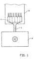
- Figure 1 shows a device for processing among other meat dough, provided with a dividing device 1 according to the invention, a vacuum fill machine 2, connected to an inlet opening of the dividing device 1 and a discharge device 3 for discharge of the various flows of material coming out of the outlet openings of the dividing device 1.
- the dividing device 1 is provided with various segments 4.
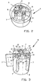
- FIG 2 shows a segment 4 of the dividing device 1 as can be seen in figure 1 .
- Each segment is provided with a housing 5 in which a vane-type rotor 6.
- the vane-type rotor 6 is provided with vanes 7 that are movable in a hub 8, longitudinally with respect to the axis of rotation of the vane-type rotor.
- the hub is provided with unround apertures 9.
- the hub is divided into sections 10 by axial grooves.
- the hub is made of a synthetic material such as nylon.
- FIG. 3 shows the vane-type rotor 6 according to the invention in detail.
- the vane-type rotor 6 comprises a hub 8 provided with axial grooves 12 that partially divide the hub into sections 10.
- a part of those sections 10 is here provided with unround apertures 9 that have been provided with a flat surface plane 11.
- the apertures are square.
- the vanes 9 can move longitudinally in the axial grooves.
- the vanes are made of metal, preferably stainless steel.
- Figure 4 Shows how various hubs 8 of the dividing device 6 can be placed onto each other for forming one continuous hub.
- connection elements such as bolts or pins, are inserted through the apertures 9, for connecting the various hubs one to the other.
- the shape of the bolts is adjusted here to the cross-section of the apertures.
- Preferably the connection elements exactly fit in the apertures.
- FIG. 5 shows the vanes 7 of the vane-type rotor 6 according to the invention. It can clearly be seen that the vanes 7 consist of continuous vane elements 14 that have ben provided with recesses 15, that are arranged in the continuous vane elements 14 in such a way that the vanes can slide longitudinally, that means perpendicular to the axis of rotation of the vane-type rotor. In the figure three vane elements are shown but two vane elements forming four vanes can also be used.
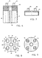
- Figure 6 shows the hub 8 of a vane-type rotor 6 according to the invention.
- the grooves 12 can clearly be seen here and continuous unround apertures 9 indicated by dots.
- the hub 8 here is provided with a metal hood 13 according to a special embodiment of the invention, which hood 13 in this embodiment is provided with pin-shaped protrusions which correspond to the unround apertures for the connection in a mutual engaging manner of the vane-type rotor of the several vane-type rotors of the various segments.
- the unround apertures 9 need not run through the entire hub 8.
- An advantage of this is a simpler assembling and disassembling, among others for cleaning, and no separate extra parts.
- Figure 7 shows a cross-section of the metal hood 13 provided with the pin-shaped protrusions 16.
- Figure 8 shows a bottom view of the hub 8 of a vane-type rotor 6 according to the invention.
- the axial grooves 12 can clearly be seen as well as the apertures 9 provided with the flat surface planes 11, in this case square apertures.
- the axial grooves 12 divide the hub 8 into sections 10. The grooves do not entirely run lengthwise through the hub. As can also be seen in figure 6 . In this example all sections have been provided with apertures for providing large torsion rigidity.
- Figure 9 shows a top view of the metal hood 13 of figure 7 .
- the synthetic hub 8 with the axial grooves 12 is indicated by dots.
- the pin-shaped protrusions 16 have a square shape and as a result correspond to the square apertures 9 as indicated in the bottom view of figure 8 .
- the operation of the dividing device is as follows.
- a fill machine guides dough material via at least one inlet opening into the dividing device.
- the flow of dough sets the vane-type rotor in motion and the vane-type rotors start rotating. As a result a constant flow of dough is ensured.
Landscapes
- Engineering & Computer Science (AREA)
- Mechanical Engineering (AREA)
- General Engineering & Computer Science (AREA)
- Rotary Pumps (AREA)
- Processing Of Meat And Fish (AREA)
Description
- The invention relates to a dividing device.
- It is common practice to supply a flow of material, preferably dough material or minced meat or stuffing for croquettes and the like, by means of a vacuum fill machine to a dividing device. As the vacuum fill machine is an expensive machine, it is preferred to provide the vacuum fill machine with a dividing device, in which the flow of material is first divided into several as identical as possible flows and which' are subsequently, dependently or independently from each other, divided into portions. It is desirable that the size and weight of the portions are repeated as accurately as possible. In many production situations it is desirable to keep the standard deviation between the portions as small as possible.
- From for instance
WO-A2-98/22206 - It is an object of the invention to overcome the drawbacks mentioned. To that end the invention relates to a dividing device provided with at least one inlet and at least two outlets and a housing provided with a chamber connected to the inlets and the outlets, and in which at least two vane-type rotors have been rotatably arranged, the vane-type rotors being provided with a plurality of axial apertures for connecting the vane-type rotors one to the other by means of connectors so that the vane-type rotors form one rotatable unit, wherein the apertures are unround. Additionally, the device comprises at least one vane-type rotor comprising a hub provided with continuous vanes which are slidable through the hub along their longitudinal axis and almost perpendicular to the axis of the hub, the hub being provided with axial grooves for holding the continuous vanes which grooves partially divide the hub in sections, a part of the sections being provided with an aperture axially through the hub, for providing a means for connecting several vane-type rotors to each other, the apertures being unround.
- It has appeared that by using unround apertures the standard deviation between the size of the portions could be reduced for a large part.
- A further reduction in the standard deviation could be realised when the apertures at the inside comprised at least one flat surface plane. Preferably the apertures have a polygonal cross-section, preferably square or triangular.
- To reduce wear and tear and to further reduce standard deviation it is preferred that the hub is provided with a metal hood at the side opposite the grooves. In most embodiments the hub will be made of synthetic material, such as for instance nylon. The slidable vanes will then for instance be made of stainless steel. In most case the metal hood is made of stainless steel as well, in connection with the corrosion and the requirements in the food industry.
- In a preferred embodiment the vane-type rotor is provided with six vanes, the vanes preferably being built from three continuous vane elements which are slidable in the hub in the grooves perpendicular to the longitudinal axis of the hub.
- An embodiment for realising the slidable vanes regards one in which two vane elements in the centre are provided with a recess on at least one longitudinal side and the third vane element is provided with recesses on both longitudinal sides, the addition sum of the depths of the recesses being at least equal to the width of a vane element.
- Preferably the smallest width of the recesses is equal to the minimal protrusion of the vanes.
- Preferably the largest width of the recesses is smaller or equal to the radius of the hub increased by the thickness of the vane elements.
- In such a dividing device particularly the vane-type rotors are preferably provided with vane elements running through the hub which elements are slidable longitudinally along their axis and perpendicular to the axis of the hub through the hub.
- Additionally the invention relates to a dividing device provided with at least one inlet and at least two outlets and a housing provided with a chamber connected to the inlet or inlets and to the outlets, and in which at least one vane-type rotor has been rotatably arranged, the vane-type rotor being provided with a synthetic hub and vane elements running through the synthetic hub which elements are slidable longitudinally along' their axis and perpendicular to the axis of the synthetic hub, the synthetic hub being provided with a metal hood.
- In particular the hub is provided with axial grooves that partly divide the hub into sections, and the hub is provided with the metal hood at the side opposite the side provided with the grooves.
- Additionally the invention relates to a vane-type rotor, suitable for a device as described above in the text.
- Said aspects of the invention can be combined if so desired.
- The invention will be further elucidated on the basis of an exemplary embodiment of a dividing device according to the invention, in which:
-
Figure 1 shows a dividing device according to the invention; -
Figure 2 shows a segment of the housing including vane-type rotor; -
Figure 3 shows a vane-type rotor according to one aspect of the invention; -
Figure 4 shows two connected hubs; -
Figure 5 shows vane elements according to an aspect of the invention; -
Figure 6 shows a longitudinal section of a hub according to the invention; -
Figure 7 shows a cross-section of the metal hood of the hub according to an aspect of the invention; -
Figure 8 shows a bottom view of a hub according to the invention; and -
Figure 9 shows a top view of a hub according to the invention at the side of the metal hood. -
Figure 1 shows a device for processing among other meat dough, provided with a dividingdevice 1 according to the invention, avacuum fill machine 2, connected to an inlet opening of the dividingdevice 1 and adischarge device 3 for discharge of the various flows of material coming out of the outlet openings of the dividingdevice 1. The dividingdevice 1 is provided withvarious segments 4. -
Figure 2 shows asegment 4 of thedividing device 1 as can be seen infigure 1 . Each segment is provided with ahousing 5 in which a vane-type rotor 6. The vane-type rotor 6 is provided withvanes 7 that are movable in ahub 8, longitudinally with respect to the axis of rotation of the vane-type rotor. The hub is provided withunround apertures 9. The hub is divided intosections 10 by axial grooves. Generally the hub is made of a synthetic material such as nylon. -
Figure 3 shows the vane-type rotor 6 according to the invention in detail. In the figure it can clearly be seen that the vane-type rotor 6 comprises ahub 8 provided withaxial grooves 12 that partially divide the hub intosections 10. A part of thosesections 10 is here provided withunround apertures 9 that have been provided with aflat surface plane 11. In this exemplary embodiment the apertures are square. Thevanes 9 can move longitudinally in the axial grooves. Generally the vanes are made of metal, preferably stainless steel. -
Figure 4 Shows howvarious hubs 8 of the dividingdevice 6 can be placed onto each other for forming one continuous hub. Here connection elements, such as bolts or pins, are inserted through theapertures 9, for connecting the various hubs one to the other. The shape of the bolts is adjusted here to the cross-section of the apertures. Preferably the connection elements exactly fit in the apertures. -
Figure 5 shows thevanes 7 of the vane-type rotor 6 according to the invention. It can clearly be seen that thevanes 7 consist ofcontinuous vane elements 14 that have ben provided withrecesses 15, that are arranged in thecontinuous vane elements 14 in such a way that the vanes can slide longitudinally, that means perpendicular to the axis of rotation of the vane-type rotor. In the figure three vane elements are shown but two vane elements forming four vanes can also be used. -
Figure 6 shows thehub 8 of a vane-type rotor 6 according to the invention. Thegrooves 12 can clearly be seen here and continuousunround apertures 9 indicated by dots. Thehub 8 here is provided with ametal hood 13 according to a special embodiment of the invention, whichhood 13 in this embodiment is provided with pin-shaped protrusions which correspond to the unround apertures for the connection in a mutual engaging manner of the vane-type rotor of the several vane-type rotors of the various segments. It should be clear that theunround apertures 9 need not run through theentire hub 8. An advantage of this is a simpler assembling and disassembling, among others for cleaning, and no separate extra parts. -
Figure 7 shows a cross-section of themetal hood 13 provided with the pin-shaped protrusions 16. -
Figure 8 shows a bottom view of thehub 8 of a vane-type rotor 6 according to the invention. Theaxial grooves 12 can clearly be seen as well as theapertures 9 provided with theflat surface planes 11, in this case square apertures. Theaxial grooves 12 divide thehub 8 intosections 10. The grooves do not entirely run lengthwise through the hub. As can also be seen infigure 6 . In this example all sections have been provided with apertures for providing large torsion rigidity. -
Figure 9 shows a top view of themetal hood 13 offigure 7 . Thesynthetic hub 8 with theaxial grooves 12 is indicated by dots. In this figure it can clearly be seen that the pin-shapedprotrusions 16 have a square shape and as a result correspond to thesquare apertures 9 as indicated in the bottom view offigure 8 . - The operation of the dividing device is as follows. A fill machine guides dough material via at least one inlet opening into the dividing device. As a result of the often high pressure, up to over 50 bar, the flow of dough sets the vane-type rotor in motion and the vane-type rotors start rotating. As a result a constant flow of dough is ensured.
- When rotating the vane-type rotors the vane elements move longitudinally and a vane will at some moment during a revolution be entirely accommodated in the hub, and during a later moment protrude maximally out of the hub.
Claims (13)
- Dividing device (1) provided with at least one inlet and at least two outlets and a housing (5) provided with a chamber connected to the inlets and the outlets, and in which at least two vane-type rotors (6) have been rotatably arranged, the vane-type rotors (6) being provided with a plurality of axial apertures (9) for connecting the vane-type rotors (6) one to the other by means of connectors so that the vane-type rotors (6) form one rotatable unit, characterized in that the apertures (9) are unround.
- Dividing device (1) according to claim 1, characterized in that the apertures (9) at their inside comprise at least one flat surface plane (11).
- Dividing device (1) according to claim 1 or 2, characterized in that the apertures (9) have a polygonal cross-section, preferably square or triangular.
- Dividing device (1) according to any of the preceding claims, characterized in that each vane-type rotor (6) is provided with vane elements (14) running through a hub (8), which vane elements are slidable through the hub (8) longitudinally along their axis and perpendicular to the axis of the hub (8).
- Dividing device (1) according to claim 4, characterized in that the vane elements (14) constitute continuous vanes (7) and in that the hub(8) is provided with axial grooves for holding the continuous vanes (7), which grooves partially divide the hub (8) in sections (10),
wherein a part of the sections (10) is provided with an aperture (9). - Dividing device (1) according to any of the preceding claims, characterized in that the hub (8) is made of a synthetic material and is provided with a metal hood (13).
- Dividing device (1) according to claims 5 and 6, characterized in that the metal hood (13) is arranged at the side of the hub (8) opposite the grooves.
- Dividing device (1) according to claim 6 or 7, characterized in that the metal hood (13) is provided with pin-shaped protrusions (16) corresponding to the unround apertures (9) for connecting the vane-type rotors (6).
- Dividing device (1) according to any of the preceding claims, characterized in that each vane-type rotor (6) is provided with six vanes (7).
- Dividing device (1) according to claim 9, characterized in that two vane elements (14) are provided in their centre with a recess (15) on at least one longitudinal side and the third vane element (14) is provided with recesses (15) on both longitudinal sides, the addition sum of the depths of the recesses (15) being at least equal to the width of a vane element (14).
- Dividing device (1) according to claim 10, characterized in that the smallest width of the recesses (15) is equal to the minimal protrusion of the vanes (17).
- Dividing device (1) according to claim 10 or 11, characterized in that the largest width of the recesses (15) is smaller or equal to the radius of the hub (8) increased by the thickness of the vane elements (14).
- Vane-type rotor (6) for use in a dividing device (1) according to any one of the preceding claims, comprising a hub (8) in which a plurality of vanes (7) are movably arranged, the hub (8) being provided with a plurality of axial apertures (9), characterized in that the apertures (9) are unround.
Applications Claiming Priority (3)
| Application Number | Priority Date | Filing Date | Title |
|---|---|---|---|
| NL1017295 | 2001-02-06 | ||
| NL1017295A NL1017295C1 (en) | 2001-02-06 | 2001-02-06 | Distribution Cabinet. |
| PCT/NL2002/000085 WO2002062459A1 (en) | 2001-02-06 | 2002-02-06 | Dividing device |
Publications (2)
| Publication Number | Publication Date |
|---|---|
| EP1358006A1 EP1358006A1 (en) | 2003-11-05 |
| EP1358006B1 true EP1358006B1 (en) | 2012-11-14 |
Family
ID=19772859
Family Applications (1)
| Application Number | Title | Priority Date | Filing Date |
|---|---|---|---|
| EP02700888A Expired - Lifetime EP1358006B1 (en) | 2001-02-06 | 2002-02-06 | Dividing device |
Country Status (4)
| Country | Link |
|---|---|
| US (1) | US7037093B2 (en) |
| EP (1) | EP1358006B1 (en) |
| NL (1) | NL1017295C1 (en) |
| WO (1) | WO2002062459A1 (en) |
Families Citing this family (4)
| Publication number | Priority date | Publication date | Assignee | Title |
|---|---|---|---|---|
| EP1592497B1 (en) * | 2003-01-20 | 2015-05-06 | DJM Foodprocessing B.V. | Distribution device |
| US7467935B2 (en) * | 2004-09-17 | 2008-12-23 | Sauer-Danfoss, Inc. | Low input torque rotor for vane pump |
| DE202009013467U1 (en) * | 2009-10-06 | 2011-02-24 | Vemag Maschinenbau Gmbh | Filling flow |
| US20180100395A1 (en) * | 2016-10-10 | 2018-04-12 | Stewart Systems Baking, LLC | Vane Powered Rotor System |
Family Cites Families (11)
| Publication number | Priority date | Publication date | Assignee | Title |
|---|---|---|---|---|
| DE54866C (en) | G. BÄUER-LEIN-GERMANN in Zürich-Unterstrafs, Beckenhofstrafse 37 | Sausage filling machine | ||
| FR640876A (en) | 1927-02-24 | 1928-07-24 | High Speed Rotary Vane Pumps Improvements | |
| US2014678A (en) * | 1931-10-24 | 1935-09-17 | Zoller Arnold | Internal combustion engine |
| US1952834A (en) * | 1932-08-26 | 1934-03-27 | Elliott W Beidler | Pump |
| US2260888A (en) * | 1939-06-23 | 1941-10-28 | Walwin L Davis | Pump |
| GB1231187A (en) * | 1967-10-09 | 1971-05-12 | ||
| CH657506A5 (en) * | 1981-12-10 | 1986-09-15 | Hollymatic Ag | PORTIONING MACHINE FOR FILLING CAVES WITH DEFORMABLE MATERIAL AND USE THEREOF. |
| JPS59168291A (en) | 1983-03-14 | 1984-09-21 | Noritake Co Ltd | Ceramic rotor for vane type pump |
| CH672819A5 (en) * | 1988-04-26 | 1989-12-29 | Waelchli Hans | |
| DE8914705U1 (en) * | 1989-12-14 | 1990-08-30 | Albert Handtmann Maschinenfabrik GmbH & Co KG, 7950 Biberach | Vane pump for conveying pasty masses, especially sausage meat |
| US5906297A (en) | 1996-11-21 | 1999-05-25 | Cole; Russell H. | Multi-outlet depositor |
-
2001
- 2001-02-06 NL NL1017295A patent/NL1017295C1/en not_active IP Right Cessation
-
2002
- 2002-02-06 EP EP02700888A patent/EP1358006B1/en not_active Expired - Lifetime
- 2002-02-06 US US10/475,947 patent/US7037093B2/en not_active Expired - Fee Related
- 2002-02-06 WO PCT/NL2002/000085 patent/WO2002062459A1/en not_active Ceased
Also Published As
| Publication number | Publication date |
|---|---|
| WO2002062459A1 (en) | 2002-08-15 |
| US7037093B2 (en) | 2006-05-02 |
| NL1017295C1 (en) | 2002-08-08 |
| US20040140322A1 (en) | 2004-07-22 |
| EP1358006A1 (en) | 2003-11-05 |
Similar Documents
| Publication | Publication Date | Title |
|---|---|---|
| DE3014425C2 (en) | Side channel pump | |
| JPH037034B2 (en) | ||
| CA2985047C (en) | Stator | |
| EP2827721B1 (en) | Arrangement and method for mixing of particulate filling into consumer ice mass | |
| DE69004087T2 (en) | LIQUID RING MACHINES. | |
| US7037093B2 (en) | Dividing device | |
| EP2616684B1 (en) | Rotary displacement pump for pumping solids emulsions, especially liquid explosives | |
| US2857111A (en) | Rotor blades and blade mounting means for grinding mills | |
| CA1051266A (en) | Rotary fluid displacement device | |
| EP0320963A3 (en) | Volumetric fluid pump working like a pump with rotary pistons | |
| EP0416948B1 (en) | Variable nozzle for a radial turbine | |
| DE69130480T2 (en) | MULTI-CHAMBER ROTATING FLAP MACHINE FOR FLUIDS WITH FORCED SLIDING SEALS | |
| EP1592497B1 (en) | Distribution device | |
| US10590929B2 (en) | Method of coupling stator/rotor laminates | |
| EP0617201B1 (en) | Filling, fluid-transporting and pumping device | |
| DE69837950T2 (en) | Rotor for rotary pump | |
| RU92300U1 (en) | DEVICE FOR FOLDING FOOD PRODUCT, STAMPING MECHANISM, DEVICE FOR PUMPING VISCOUS MEDIA AND DEVICE FOR MANUFACTURING SEMI-FINISHED PRODUCTS FROM BAKING TEST | |
| RU2141578C1 (en) | Rotary displacement type machine | |
| US3824045A (en) | Variable-capacity sliding-vane pump | |
| US4599057A (en) | Rotary blade machine with blade end sealing | |
| EP1937980A1 (en) | Rotor for a rotary machine and a rotary machine | |
| US3785574A (en) | Swash-type impeller pumps | |
| EP3292308B1 (en) | Stator | |
| DE102005008388A1 (en) | Impeller wheel for side channel machine, e.g. compressors and vacuum pumps, has at least one guide rib between adjacent blades extending inwards into cross-sectional region(s) of radial outer edging of flow chamber | |
| EP1264988B1 (en) | Screw rotor tip |
Legal Events
| Date | Code | Title | Description |
|---|---|---|---|
| PUAI | Public reference made under article 153(3) epc to a published international application that has entered the european phase |
Free format text: ORIGINAL CODE: 0009012 |
|
| 17P | Request for examination filed |
Effective date: 20030827 |
|
| AK | Designated contracting states |
Kind code of ref document: A1 Designated state(s): AT BE CH CY DE DK ES FI FR GB GR IE IT LI LU MC NL PT SE TR |
|
| AX | Request for extension of the european patent |
Extension state: AL LT LV MK RO SI |
|
| 17Q | First examination report despatched |
Effective date: 20080102 |
|
| 19U | Interruption of proceedings before grant |
Effective date: 20100426 |
|
| 19W | Proceedings resumed before grant after interruption of proceedings |
Effective date: 20110201 |
|
| RAP1 | Party data changed (applicant data changed or rights of an application transferred) |
Owner name: DE JONG ENGINEERING ELBURG B.V. |
|
| RAP1 | Party data changed (applicant data changed or rights of an application transferred) |
Owner name: DJM FOODPROCESSING B.V. |
|
| REG | Reference to a national code |
Ref country code: DE Ref legal event code: R079 Ref document number: 60244032 Country of ref document: DE Free format text: PREVIOUS MAIN CLASS: B01F0015040000 Ipc: F04C0002344000 |
|
| RIC1 | Information provided on ipc code assigned before grant |
Ipc: F04C 2/344 20060101AFI20120228BHEP Ipc: F01C 21/08 20060101ALI20120228BHEP |
|
| GRAP | Despatch of communication of intention to grant a patent |
Free format text: ORIGINAL CODE: EPIDOSNIGR1 |
|
| GRAS | Grant fee paid |
Free format text: ORIGINAL CODE: EPIDOSNIGR3 |
|
| RAP1 | Party data changed (applicant data changed or rights of an application transferred) |
Owner name: DJM FOODPROCESSING B.V. |
|
| GRAA | (expected) grant |
Free format text: ORIGINAL CODE: 0009210 |
|
| AK | Designated contracting states |
Kind code of ref document: B1 Designated state(s): AT BE CH CY DE DK ES FI FR GB GR IE IT LI LU MC NL PT SE TR |
|
| REG | Reference to a national code |
Ref country code: GB Ref legal event code: FG4D |
|
| REG | Reference to a national code |
Ref country code: CH Ref legal event code: EP Ref country code: AT Ref legal event code: REF Ref document number: 584145 Country of ref document: AT Kind code of ref document: T Effective date: 20121115 |
|
| REG | Reference to a national code |
Ref country code: IE Ref legal event code: FG4D |
|
| REG | Reference to a national code |
Ref country code: DE Ref legal event code: R096 Ref document number: 60244032 Country of ref document: DE Effective date: 20130110 |
|
| REG | Reference to a national code |
Ref country code: NL Ref legal event code: T3 |
|
| REG | Reference to a national code |
Ref country code: AT Ref legal event code: MK05 Ref document number: 584145 Country of ref document: AT Kind code of ref document: T Effective date: 20121114 |
|
| PG25 | Lapsed in a contracting state [announced via postgrant information from national office to epo] |
Ref country code: SE Free format text: LAPSE BECAUSE OF FAILURE TO SUBMIT A TRANSLATION OF THE DESCRIPTION OR TO PAY THE FEE WITHIN THE PRESCRIBED TIME-LIMIT Effective date: 20121114 Ref country code: FI Free format text: LAPSE BECAUSE OF FAILURE TO SUBMIT A TRANSLATION OF THE DESCRIPTION OR TO PAY THE FEE WITHIN THE PRESCRIBED TIME-LIMIT Effective date: 20121114 Ref country code: ES Free format text: LAPSE BECAUSE OF FAILURE TO SUBMIT A TRANSLATION OF THE DESCRIPTION OR TO PAY THE FEE WITHIN THE PRESCRIBED TIME-LIMIT Effective date: 20130225 |
|
| PG25 | Lapsed in a contracting state [announced via postgrant information from national office to epo] |
Ref country code: CY Free format text: LAPSE BECAUSE OF FAILURE TO SUBMIT A TRANSLATION OF THE DESCRIPTION OR TO PAY THE FEE WITHIN THE PRESCRIBED TIME-LIMIT Effective date: 20121114 Ref country code: GR Free format text: LAPSE BECAUSE OF FAILURE TO SUBMIT A TRANSLATION OF THE DESCRIPTION OR TO PAY THE FEE WITHIN THE PRESCRIBED TIME-LIMIT Effective date: 20130215 Ref country code: PT Free format text: LAPSE BECAUSE OF FAILURE TO SUBMIT A TRANSLATION OF THE DESCRIPTION OR TO PAY THE FEE WITHIN THE PRESCRIBED TIME-LIMIT Effective date: 20130314 |
|
| PG25 | Lapsed in a contracting state [announced via postgrant information from national office to epo] |
Ref country code: AT Free format text: LAPSE BECAUSE OF FAILURE TO SUBMIT A TRANSLATION OF THE DESCRIPTION OR TO PAY THE FEE WITHIN THE PRESCRIBED TIME-LIMIT Effective date: 20121114 |
|
| PG25 | Lapsed in a contracting state [announced via postgrant information from national office to epo] |
Ref country code: DK Free format text: LAPSE BECAUSE OF FAILURE TO SUBMIT A TRANSLATION OF THE DESCRIPTION OR TO PAY THE FEE WITHIN THE PRESCRIBED TIME-LIMIT Effective date: 20121114 |
|
| PG25 | Lapsed in a contracting state [announced via postgrant information from national office to epo] |
Ref country code: IT Free format text: LAPSE BECAUSE OF FAILURE TO SUBMIT A TRANSLATION OF THE DESCRIPTION OR TO PAY THE FEE WITHIN THE PRESCRIBED TIME-LIMIT Effective date: 20121114 |
|
| PLBE | No opposition filed within time limit |
Free format text: ORIGINAL CODE: 0009261 |
|
| STAA | Information on the status of an ep patent application or granted ep patent |
Free format text: STATUS: NO OPPOSITION FILED WITHIN TIME LIMIT |
|
| PG25 | Lapsed in a contracting state [announced via postgrant information from national office to epo] |
Ref country code: MC Free format text: LAPSE BECAUSE OF NON-PAYMENT OF DUE FEES Effective date: 20130228 |
|
| REG | Reference to a national code |
Ref country code: CH Ref legal event code: PL |
|
| 26N | No opposition filed |
Effective date: 20130815 |
|
| PG25 | Lapsed in a contracting state [announced via postgrant information from national office to epo] |
Ref country code: CH Free format text: LAPSE BECAUSE OF NON-PAYMENT OF DUE FEES Effective date: 20130228 Ref country code: LI Free format text: LAPSE BECAUSE OF NON-PAYMENT OF DUE FEES Effective date: 20130228 |
|
| REG | Reference to a national code |
Ref country code: IE Ref legal event code: MM4A |
|
| REG | Reference to a national code |
Ref country code: DE Ref legal event code: R097 Ref document number: 60244032 Country of ref document: DE Effective date: 20130815 |
|
| PG25 | Lapsed in a contracting state [announced via postgrant information from national office to epo] |
Ref country code: IE Free format text: LAPSE BECAUSE OF NON-PAYMENT OF DUE FEES Effective date: 20130206 |
|
| PG25 | Lapsed in a contracting state [announced via postgrant information from national office to epo] |
Ref country code: TR Free format text: LAPSE BECAUSE OF FAILURE TO SUBMIT A TRANSLATION OF THE DESCRIPTION OR TO PAY THE FEE WITHIN THE PRESCRIBED TIME-LIMIT Effective date: 20121114 |
|
| PG25 | Lapsed in a contracting state [announced via postgrant information from national office to epo] |
Ref country code: LU Free format text: LAPSE BECAUSE OF NON-PAYMENT OF DUE FEES Effective date: 20130206 |
|
| REG | Reference to a national code |
Ref country code: FR Ref legal event code: PLFP Year of fee payment: 15 |
|
| REG | Reference to a national code |
Ref country code: FR Ref legal event code: PLFP Year of fee payment: 16 |
|
| REG | Reference to a national code |
Ref country code: FR Ref legal event code: PLFP Year of fee payment: 17 |
|
| PGFP | Annual fee paid to national office [announced via postgrant information from national office to epo] |
Ref country code: NL Payment date: 20180226 Year of fee payment: 17 |
|
| PGFP | Annual fee paid to national office [announced via postgrant information from national office to epo] |
Ref country code: GB Payment date: 20180227 Year of fee payment: 17 Ref country code: DE Payment date: 20180227 Year of fee payment: 17 |
|
| PGFP | Annual fee paid to national office [announced via postgrant information from national office to epo] |
Ref country code: FR Payment date: 20180227 Year of fee payment: 17 Ref country code: BE Payment date: 20180227 Year of fee payment: 17 |
|
| REG | Reference to a national code |
Ref country code: DE Ref legal event code: R119 Ref document number: 60244032 Country of ref document: DE |
|
| REG | Reference to a national code |
Ref country code: NL Ref legal event code: MM Effective date: 20190301 |
|
| GBPC | Gb: european patent ceased through non-payment of renewal fee |
Effective date: 20190206 |
|
| REG | Reference to a national code |
Ref country code: BE Ref legal event code: MM Effective date: 20190228 |
|
| PG25 | Lapsed in a contracting state [announced via postgrant information from national office to epo] |
Ref country code: DE Free format text: LAPSE BECAUSE OF NON-PAYMENT OF DUE FEES Effective date: 20190903 Ref country code: NL Free format text: LAPSE BECAUSE OF NON-PAYMENT OF DUE FEES Effective date: 20190301 Ref country code: GB Free format text: LAPSE BECAUSE OF NON-PAYMENT OF DUE FEES Effective date: 20190206 |
|
| PG25 | Lapsed in a contracting state [announced via postgrant information from national office to epo] |
Ref country code: BE Free format text: LAPSE BECAUSE OF NON-PAYMENT OF DUE FEES Effective date: 20190228 Ref country code: FR Free format text: LAPSE BECAUSE OF NON-PAYMENT OF DUE FEES Effective date: 20190228 |